EP0896654B1 - Compression joint - Google Patents
Compression joint Download PDFInfo
- Publication number
- EP0896654B1 EP0896654B1 EP98903215A EP98903215A EP0896654B1 EP 0896654 B1 EP0896654 B1 EP 0896654B1 EP 98903215 A EP98903215 A EP 98903215A EP 98903215 A EP98903215 A EP 98903215A EP 0896654 B1 EP0896654 B1 EP 0896654B1
- Authority
- EP
- European Patent Office
- Prior art keywords
- coupling
- composite pipe
- set forth
- pipe
- ribs
- Prior art date
- Legal status (The legal status is an assumption and is not a legal conclusion. Google has not performed a legal analysis and makes no representation as to the accuracy of the status listed.)
- Expired - Lifetime
Links
Images
Classifications
-
- F—MECHANICAL ENGINEERING; LIGHTING; HEATING; WEAPONS; BLASTING
- F16—ENGINEERING ELEMENTS AND UNITS; GENERAL MEASURES FOR PRODUCING AND MAINTAINING EFFECTIVE FUNCTIONING OF MACHINES OR INSTALLATIONS; THERMAL INSULATION IN GENERAL
- F16L—PIPES; JOINTS OR FITTINGS FOR PIPES; SUPPORTS FOR PIPES, CABLES OR PROTECTIVE TUBING; MEANS FOR THERMAL INSULATION IN GENERAL
- F16L13/00—Non-disconnectible pipe-joints, e.g. soldered, adhesive or caulked joints
- F16L13/14—Non-disconnectible pipe-joints, e.g. soldered, adhesive or caulked joints made by plastically deforming the material of the pipe, e.g. by flanging, rolling
- F16L13/141—Non-disconnectible pipe-joints, e.g. soldered, adhesive or caulked joints made by plastically deforming the material of the pipe, e.g. by flanging, rolling by crimping or rolling from the outside
- F16L13/143—Non-disconnectible pipe-joints, e.g. soldered, adhesive or caulked joints made by plastically deforming the material of the pipe, e.g. by flanging, rolling by crimping or rolling from the outside with a sealing element placed around the male part before crimping or rolling
-
- F—MECHANICAL ENGINEERING; LIGHTING; HEATING; WEAPONS; BLASTING
- F16—ENGINEERING ELEMENTS AND UNITS; GENERAL MEASURES FOR PRODUCING AND MAINTAINING EFFECTIVE FUNCTIONING OF MACHINES OR INSTALLATIONS; THERMAL INSULATION IN GENERAL
- F16L—PIPES; JOINTS OR FITTINGS FOR PIPES; SUPPORTS FOR PIPES, CABLES OR PROTECTIVE TUBING; MEANS FOR THERMAL INSULATION IN GENERAL
- F16L33/00—Arrangements for connecting hoses to rigid members; Rigid hose connectors, i.e. single members engaging both hoses
- F16L33/01—Arrangements for connecting hoses to rigid members; Rigid hose connectors, i.e. single members engaging both hoses adapted for hoses having a multi-layer wall
-
- F—MECHANICAL ENGINEERING; LIGHTING; HEATING; WEAPONS; BLASTING
- F16—ENGINEERING ELEMENTS AND UNITS; GENERAL MEASURES FOR PRODUCING AND MAINTAINING EFFECTIVE FUNCTIONING OF MACHINES OR INSTALLATIONS; THERMAL INSULATION IN GENERAL
- F16L—PIPES; JOINTS OR FITTINGS FOR PIPES; SUPPORTS FOR PIPES, CABLES OR PROTECTIVE TUBING; MEANS FOR THERMAL INSULATION IN GENERAL
- F16L33/00—Arrangements for connecting hoses to rigid members; Rigid hose connectors, i.e. single members engaging both hoses
- F16L33/18—Arrangements for connecting hoses to rigid members; Rigid hose connectors, i.e. single members engaging both hoses characterised by the use of additional sealing means
-
- F—MECHANICAL ENGINEERING; LIGHTING; HEATING; WEAPONS; BLASTING
- F16—ENGINEERING ELEMENTS AND UNITS; GENERAL MEASURES FOR PRODUCING AND MAINTAINING EFFECTIVE FUNCTIONING OF MACHINES OR INSTALLATIONS; THERMAL INSULATION IN GENERAL
- F16L—PIPES; JOINTS OR FITTINGS FOR PIPES; SUPPORTS FOR PIPES, CABLES OR PROTECTIVE TUBING; MEANS FOR THERMAL INSULATION IN GENERAL
- F16L33/00—Arrangements for connecting hoses to rigid members; Rigid hose connectors, i.e. single members engaging both hoses
- F16L33/30—Arrangements for connecting hoses to rigid members; Rigid hose connectors, i.e. single members engaging both hoses comprising parts inside the hoses only
Definitions
- the present invention relates to a connecting part for a Press connection and a press connection produced therewith.
- Connecting parts made of plastic for producing a press connection are known for example from CH 682 942 A5.
- the connecting part shown there is made of plastic and contains Circumferential areas on which a pipe, in particular a composite pipe is pressed on.
- a groove is provided within the circumferential area, in which a Retaining ring made of metal is held outwards has sharp edges. This ring ensures even at high axial tensile forces a secure non-positive and positive Connection between the composite pipe and the connecting part.
- the base body of the connecting part made of plastic there are no corrosion problems, e.g. for connecting parts are known from brass.
- suitable plastics polyolefin and cross-linked polyethylene are given. This Connector works relatively well, but is in its Long-term behavior, especially when very strong temperature changes occur not entirely satisfactory. Also makes the metal circlip the production complex.
- PVDF plastic Polyvinylidene fluoride
- the connecting part made of PVDF meets all hygienic requirements Requirements under the Drinking Water Ordinance be put. Corrosion problems, especially in interaction with other metals, do not occur.
- the connecting pipe or pipes are on the Postponed connecting part, which in the peripheral area several has circumferential ribs. There is also a circumferential sealing ring provided as an additional seal between serves the connecting part and the composite pipe.
- the axial securing of the composite pipe can also preferably be carried out by sawtooth-shaped ribs may be provided on the composite part. Ribs are then preferably in two axial areas in one uniform orientation arranged, the orientation the same in the two axial areas (only train protection) or can be opposite (pressure and train protection).
- the sawtooth-shaped Ribs with the sharp outer edge are, however preferably aligned in one direction such that the The composite pipe is secured against tension on the connecting part Pressure can be secured by a radial stop surface his. Sealing rings can be between ribbed areas or also at the flange end of the connecting part.
- a step-like formation of the peripheral region may be provided.
- the steps are an axial securing on the one hand and others achieved greater tightness. It works when pressed a more intensive shape intervention of the composite pipe the connecting part.
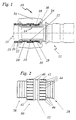
- Fig. 1 shows a press connection 10 with a tubular connecting part 12, a circumferential area at at least one free end 14, which for pressing a composite pipe 16 is determined.
- the composite pipe 16 is usually from an inner layer 18 of cross-linked polyethylene, an intermediate layer 20 made of aluminum and an outer layer 22 made of polyethylene.
- This composite pipe 16 is on the free end of the connecting part 12 pushed on until its end face on one abuts circumferential projection 24 of the connecting part.
- the for Pressing with the circumferential region 14 provided with the composite pipe of the connecting part 12 contains two smaller-diameter ribbed Areas 26, 28 defined by a raised area 30 are separated from each other.
- the peripheral area 14 will be later described in more detail in connection with FIG. 2.
- Raised, somewhat larger area 30 is a groove 32 provided for receiving an O-ring seal 34.
- the composite pipe is by pliers 36 on the connecting part 12th pressed on.
- the composite pipe 12 has the property that it after remains irreversibly deformed when pressed. Therefore, the Crimping pliers also profiled areas that the profiled Areas in the intended for pressing with the composite pipe 16 Correspond to the peripheral region 14 of the connecting part 12.
- the crimping tool 36 has a groove 38 which is form-fitting cooperates with the projection 24 of the connecting part, so that a precise axial fit of the pressing tongs 36 on the outer circumference 14 of the Connecting part 12 is achieved.
- the connecting part 12 consisting of polyvinylidene fluoride, is very precise to the surface, resistant to temperature and pressure changes and has a long lifespan, making it long-term stable Press connection of the connecting part 12 with the composite pipe 16 is achieved.
- the irreversible deformation of the composite pipe 14 is primarily characterized by the liner Aluminum causes.
- the raised area 30 contains the groove 32 for the sealing ring 34 and on both sides of the groove 32 a raised, smooth ring area 40, to each of which an axial area 42 is connected on the outside, which has a plurality of first and second sawtooth ribs 44 and 46 over the circumference .
- the first sawtooth ribs 44 are oriented in a first direction and the second ribs 46 are oriented opposite to the first ribs 44.
Landscapes
- Engineering & Computer Science (AREA)
- General Engineering & Computer Science (AREA)
- Mechanical Engineering (AREA)
- Non-Disconnectible Joints And Screw-Threaded Joints (AREA)
- Coupling Device And Connection With Printed Circuit (AREA)
- Mechanical Coupling Of Light Guides (AREA)
- Infusion, Injection, And Reservoir Apparatuses (AREA)
- Paper (AREA)
- Magnetically Actuated Valves (AREA)
- Joints Allowing Movement (AREA)
- Meat, Egg Or Seafood Products (AREA)
- Connections Arranged To Contact A Plurality Of Conductors (AREA)
- Flanged Joints, Insulating Joints, And Other Joints (AREA)
- Quick-Acting Or Multi-Walled Pipe Joints (AREA)
- Lining Or Joining Of Plastics Or The Like (AREA)
- Joints With Sleeves (AREA)
- Rigid Pipes And Flexible Pipes (AREA)
Abstract
Description
Die vorliegende Erfindung betrifft ein Verbindungsteil für eine Preßverbindung und eine damit hergestellte Preßverbindung.The present invention relates to a connecting part for a Press connection and a press connection produced therewith.
Verbindungsteile aus Kunststoff zur Herstellung einer Preßverbindung sind beispielsweise aus der CH 682 942 A5 bekannt. Das dort gezeigte Verbindungsteil besteht aus Kunststoff und enthält Umfangsbereiche, auf die ein Rohr, insbesondere ein Verbundrohr aufgepreßt ist. Bei dem bekannten Verbindungsteil ist innerhalb des Umfangsbereichs eine Nut vorgesehen, in der ein Sicherungsring aus Metall gehalten ist, der nach außen hin scharfe Kanten aufweist. Dieser Ring gewährleistet auch bei hohen axialen Zugkräften eine sichere kraft- und formschlüssige Verbindung zwischen dem Verbundrohr und dem Verbindungsteil. Da der Grundkörper des Verbindungsteils aus Kunststoff hergestellt ist, treten keine Korrosionsprobleme auf, die z.B. bei Verbindungsteilen aus Messing bekannt sind. Als geeignete Kunststoffe werden Polyolefin und vernetztes Polyethylen angegeben. Dieses Verbindungsteil funktioniert relativ gut, ist jedoch in seinem Dauerverhalten insbesondere bei Auftreten sehr starker Temperaturwechsel nicht vollkommen zufriedenstellend. Außerdem macht der Metall- Sicherungsring die Herstellung aufwendig.Connecting parts made of plastic for producing a press connection are known for example from CH 682 942 A5. The connecting part shown there is made of plastic and contains Circumferential areas on which a pipe, in particular a composite pipe is pressed on. In the known connecting part a groove is provided within the circumferential area, in which a Retaining ring made of metal is held outwards has sharp edges. This ring ensures even at high axial tensile forces a secure non-positive and positive Connection between the composite pipe and the connecting part. There the base body of the connecting part made of plastic there are no corrosion problems, e.g. for connecting parts are known from brass. As suitable plastics polyolefin and cross-linked polyethylene are given. This Connector works relatively well, but is in its Long-term behavior, especially when very strong temperature changes occur not entirely satisfactory. Also makes the metal circlip the production complex.
Es ist daher Aufgabe der vorliegenden Erfindung, ein Verbindungsteil für eine Preßverbindung und eine Preßverbindung zu schaffen, die bei kostengünstiger Herstellung für hohe Drücke geeignet sind und auch bei stärkeren Temperaturwechseln eine hohe Lebensdauer und Zuverlässigkeit aufweisen.It is therefore an object of the present invention to provide a connecting part for a press connection and a press connection create that at low cost manufacturing for high pressures are suitable and also with strong temperature changes have a long service life and reliability.
Diese Aufgabe wird durch ein Verbindungsteil gemäß Anspruch 1 und eine Preßverbindung gemäß Anspruch 8 gelöst.This object is achieved by a connecting part according to claim 1 and a press connection according to claim 8 solved.
Es wurde überraschenderweise festgestellt, daß der Kunststoff Polyvinylidenfluorid (PVDF), der in R. Schenider und Th. Köhler "Ein Beitrag zur Verwendung von Kunststoffrohren, in der Versorgungstechnik" gwf Wasser. Abwasser 134 (1993) Nr. 1, Seiten 25-33 als sehr geeignet für bestimmte Spezialanwendungen beschrieben, aber für derartige Leitungsteile und Fittings bisher ungebräuchlich ist, aufgrund seiner sehr guten Eigenschaften wie Druckbeständigkeit, Langzeitstabilität und Temperaturwechselbeständigkeit sehr geeignet ist für eine Pressverbindung, wobei sich wegen der hohen Oberflächenqualität eine ausreichende axiale Sicherung auch ohne zusätzlichen Metall- Sicherungsring erzielen läßt.It was surprisingly found that the plastic Polyvinylidene fluoride (PVDF), which in R. Schenider and Th. Köhler "A contribution to the use of plastic pipes in supply engineering" gwf water. Abwasser 134 (1993) No. 1, pages 25-33 described as very suitable for certain special applications, but so far for such line parts and fittings is unusual because of its very good properties such as pressure resistance, long-term stability and resistance to temperature changes is very suitable for a press connection, a sufficient because of the high surface quality axial locking even without an additional metal locking ring can be achieved.
Das aus PVDF hergestellte Verbindungsteil erfüllt alle hygienischen Anforderungen, die im Rahmen der Trinkwasserverordnung gestellt werden. Korrosionsprobleme, insbesondere im Zusammenwirken mit anderen Metallen, treten nicht auf.The connecting part made of PVDF meets all hygienic requirements Requirements under the Drinking Water Ordinance be put. Corrosion problems, especially in interaction with other metals, do not occur.
Das Verbindungsrohr oder die Verbindungsrohre werden auf das Verbindungsteil aufgeschoben, welches im Umfangsbereich mehrere umlaufende Rippen aufweist. Weiterhin ist ein umlaufender Dichtungsring vorgesehen, der als zusätzliche Abdichtung zwischen dem Verbindungsteil und dem Verbundrohr dient.The connecting pipe or pipes are on the Postponed connecting part, which in the peripheral area several has circumferential ribs. There is also a circumferential sealing ring provided as an additional seal between serves the connecting part and the composite pipe.
Bevorzugt kann die axiale Sicherung des Verbundrohrs auch durch sägezahnförmige Rippen am Verbundteil vorgesehen sein. Die Rippen sind dann vorzugsweise in zwei axialen Bereichen in einer einheitlichen Orientierung angeordnet, wobei die Orientierung in den beiden axialen Bereichen gleich (nur Zugsicherung) oder entgegengesetzt (Druck- und Zugsicherung) sein kann. Die sägezahnförmigen Rippen mit der scharfen Außenkante sind jedoch vorzugsweise in einer Richtung derart ausgerichtet, daß das Verbundrohr gegen Zug an dem Verbindungsteil gesichert ist Gegen Druck kann es durch eine radiale Anschlagfläche gesichert sein. Dichtungsringe können sich zwischen gerippten Bereichen oder auch am Flanschende des Verbindungsteils befinden.The axial securing of the composite pipe can also preferably be carried out by sawtooth-shaped ribs may be provided on the composite part. Ribs are then preferably in two axial areas in one uniform orientation arranged, the orientation the same in the two axial areas (only train protection) or can be opposite (pressure and train protection). The sawtooth-shaped Ribs with the sharp outer edge are, however preferably aligned in one direction such that the The composite pipe is secured against tension on the connecting part Pressure can be secured by a radial stop surface his. Sealing rings can be between ribbed areas or also at the flange end of the connecting part.
Zusätzlich zu einer Verrippung des Umfangsbereichs kann eine stufenförmige Ausbildung des Umfangsbereichs vorgesehen sein. Durch die Stufen wird zum einen eine axiale Sicherung und zum anderen eine größere Dichtheit erzielt. Sie bewirkt beim Verpressen einen intensiveren Formeingriff des Verbundrohres mit dem Verbindungsteil. In addition to ribbing the peripheral area, a step-like formation of the peripheral region may be provided. The steps are an axial securing on the one hand and others achieved greater tightness. It works when pressed a more intensive shape intervention of the composite pipe the connecting part.
Die Erfindung wird nachfolgend beispielsweise anhand eines Ausführungsbeispiels in Verbindung mit der schematischen Zeichnung beschrieben. In dieser zeigen:
- Fig. 1
- eine teilgeschnittene Seitenansicht einer Preßverbin dung mit einem Verbindungsteil, einem Verbundrohr und einer Preßzange, und
- Fig. 2
- eine vergrößerte Ansicht des für die Verpressung des Verbundrohres bestimmten Umfangsbereich des Verbindungsteils aus Fig. 1.
- Fig. 1
- a partially sectioned side view of a Preßverbin tion with a connecting part, a composite pipe and a pressing tongs, and
- Fig. 2
- 3 shows an enlarged view of the peripheral region of the connecting part from FIG. 1 intended for pressing the composite pipe.
Fig. 1 zeigt eine Preßverbindung 10 mit einem rohrförmigen Verbindungsteil
12, das an zumindest einem freien Ende einen Umfangsbereich
14 aufweist, der zum Verpressen eines Verbundrohres
16 bestimmt ist. Das Verbundrohr 16 besteht in der Regel
aus einer Innenlage 18 vernetztem Polyethylen, einer Zwischenlage
20 aus Aluminium und einer Außenlage 22 aus Polyethylen.
Dieses Verbundrohr 16 wird auf das freie Ende des Verbindungsteils
12 aufgeschoben, bis es mit seiner Stirnseite an einem
umlaufenden Vorsprung 24 des Verbindungsteils anstößt. Der zur
Verpressung mit dem Verbundrohr vorgesehene Umfangsbereich 14
des Verbindungsteils 12 enthält zwei durchmesserkleinere gerippte
Bereiche 26, 28, die durch einen erhabenen Bereich 30
voneinander getrennt sind. Der Umfangsbereich 14 wird später
noch detaillierter in Verbindung mit Fig. 2 beschrieben. In dem
erhabenen, etwas durchmesserstärkeren Bereich 30 ist eine Nut
32 zur Aufnahme einer O-Ring-Dichtung 34 vorgesehen. Das Verbundrohr
wird durch eine Zange 36 auf das Verbindungsteil 12
aufgepreßt. Das Verbundrohr 12 hat die Eigenschaft, daß es nach
dem Aufpressen irreversibel verformt bleibt. Daher hat die
Preßzange ebenfalls profilierte Bereiche, die den profilierten
Bereichen im zur Verpressung mit dem Verbundrohr 16 vorgesehenen
Umfangsbereich 14 des Verbindungsteils 12 entsprechen. Zusätzlich
hat die Preßzange 36 eine Nut 38, die formschlüssig
mit dem Vorsprung 24 des Verbindungsteils zusammenwirkt, so daß
ein genauer axialer Sitz der Preßzange 36 am Außenumfang 14 des
Verbindungsteils 12 erzielt wird. Beim Verpressen schneiden
sich die in Umfangsrichtung verlaufenden Rippen in den Bereichen
26, 28 in die Innenschicht 18 des Verbundrohres 16 ein und
bewirken so eine Dichtigkeit als auch eine axiale Sicherung.
Eine zusätzliche Dichtigkeit und axiale Sicherung werden durch
den unterschiedlichen Durchmesser der gerippten Bereiche 26 und
28 einerseits und des erhabenen Bereiches 30 andererseits realisiert.
Das Verbindungsteil 12 bestehend aus Polyvinylidenfluorid,
ist sehr oberflächengenau, temperatur- und druckwechselbeständig
und hat eine lange Lebensdauer, wodurch eine langzeitstabile
Preßverbindung des Verbindungsteils 12 mit dem Verbundrohr
16 erzielt wird. Die irreversible Verformung des Verbundrohres
14 wird in erster Linie durch die Zwischenlage aus
Aluminium bewirkt.Fig. 1 shows a
Fig. 2 zeigt eine Detailansicht des Umfangsbereichs 14 mit den
beiden gerippten axialen Abschnitten 26,28 und dem dazwischen
angeordneten erhabenen Bereich 30.
Der erhabene Bereich 30 enthält die Nut 32 für den Dichtungsring
34 und beidseitig der Nut 32 jeweils einen erhöhten glatten
Ringbereich 40, an den sich außenseitig jeweils ein axialer
Bereich 42 anschließt, der über den Umfang eine Vielzahl von
ersten und zweiten Sägezahnrippen 44 und 46 aufweist. Die ersten
Sägezahnrippen 44 sind in eine erste Richtung orientiert,
und die zweiten Rippen 46 sind entgegengesetzt zu den ersten
Rippen 44 orientiert. Diese radial angeordneten Rippen, die
sich nur über einen geringen Umfangswinkel erstrecken, dienen
als Drehsicherung für das Verbundrohr, wobei die entgegengesetzte
Orientierung der beiden Rippen 44 und 46 eine Drehsicherung
in beide Drehrichtungen bewirkt.2 shows a detailed view of the
The raised
Claims (8)
- A coupling for producing a compression joint with at least one pipe, especially a composite pipe (16), which is compressed tight by an irreversible deformation or a compression collar radially against said coupling (12), comprising a tubular basic body on whose outer periphery there is at least one peripheral area (14) against which said pipe (16) is tightly compressed radially, in which at least one peripheral groove (32) is provided to receive an O-ring (34) of an elastic material axially secured and projecting radially to the outside, characterized in that said basic body is made of polyvinylidene fluoride (PVDF) and peripheral ribs having a sharp top edge are provided in said parts (26, 28) of said peripheral area (14).
- The coupling as set forth in claim 1, characterized in that said ribs are configured sawtooth-shaped.
- The coupling as set forth in claim 1 or 2, characterized in that said O-ring (34) is arranged in said peripheral area (14) provided for compressing with said composite pipe (16) between two ribbed areas (26, 28).
- The coupling as set forth in any of the claims 1 to 3, characterized in that said groove (32) is arranged in a section (30) with a larger diameter in said peripheral area (14) provided for compressing with said composite pipe (16).
- The coupling as set forth in claim 4, characterized in that in said part (30) with the larger diameter of said peripheral area (14) provided for compressing with said composite pipe (16) there are axial ribs (44, 46) for rotationally locking said composite pipe (16) on said coupling (12)
- The coupling as set forth in claim 5, characterized in that said ribs (44, 46) are configured sawtooth-shaped and opposingly oriented on both sides of said groove (32).
- The coupling as set forth in any of the preceding claims, characterized in that it comprises a peripheral protuberance (24) forming an axial stop for said composite pipe (16).
- A compression joint comprising a coupling (12) as set forth in any of the preceding claims and at least one composite pipe (16) mounted thereon containingan inner layer (18) of crosslinked polyethylene,an intermediate layer (20) of aluminum andan outer layer (22) of polyethylene.
Priority Applications (1)
| Application Number | Priority Date | Filing Date | Title |
|---|---|---|---|
| SI9830067T SI0896654T1 (en) | 1997-02-25 | 1998-02-04 | Compression joint |
Applications Claiming Priority (3)
| Application Number | Priority Date | Filing Date | Title |
|---|---|---|---|
| DE19707827 | 1997-02-25 | ||
| DE19707827A DE19707827C2 (en) | 1997-02-25 | 1997-02-25 | Press connection |
| PCT/IB1998/000226 WO1998038449A1 (en) | 1997-02-25 | 1998-02-04 | Compression joint |
Publications (2)
| Publication Number | Publication Date |
|---|---|
| EP0896654A1 EP0896654A1 (en) | 1999-02-17 |
| EP0896654B1 true EP0896654B1 (en) | 2001-10-24 |
Family
ID=7821628
Family Applications (1)
| Application Number | Title | Priority Date | Filing Date |
|---|---|---|---|
| EP98903215A Expired - Lifetime EP0896654B1 (en) | 1997-02-25 | 1998-02-04 | Compression joint |
Country Status (10)
| Country | Link |
|---|---|
| US (1) | US6145892A (en) |
| EP (1) | EP0896654B1 (en) |
| AT (1) | ATE207589T1 (en) |
| AU (1) | AU729585B2 (en) |
| DE (3) | DE19707827C2 (en) |
| DK (1) | DK0896654T3 (en) |
| ES (1) | ES2163851T3 (en) |
| PL (1) | PL328782A1 (en) |
| PT (1) | PT896654E (en) |
| WO (1) | WO1998038449A1 (en) |
Families Citing this family (24)
| Publication number | Priority date | Publication date | Assignee | Title |
|---|---|---|---|---|
| DE10137078B8 (en) * | 2001-07-28 | 2005-04-14 | Uponor Innovation Ab | Press fitting for pipes |
| DE29900796U1 (en) * | 1998-04-03 | 1999-04-08 | Geberit Technik Ag, Jona | Device for connecting a pipe socket, tubular fitting or fittings to a pipe |
| US6270125B1 (en) * | 1999-10-06 | 2001-08-07 | Mercury Plastics, Inc. | Molded tubing assemblies |
| DE50004637D1 (en) | 1999-10-28 | 2004-01-15 | Uponor Innovation Ab | Press fitting for a pipe |
| DE50001805D1 (en) * | 2000-09-04 | 2003-05-22 | Knipping Daniel | Device for producing an inseparable connection between the end region of a pipe and a connecting element |
| WO2002081188A1 (en) * | 2001-04-03 | 2002-10-17 | Geberit Technik Ag | Multi-layer fluid conduit for the sanitary and heating sectors |
| PL201764B1 (en) | 2001-07-28 | 2009-05-29 | Uponor Innovation Ab | Compression fitting for tubes |
| EP1470356B1 (en) * | 2002-01-28 | 2006-05-17 | Geberit Technik Ag | Press connection |
| US20040161563A1 (en) * | 2003-02-19 | 2004-08-19 | Wellman Raymond L. | Slip collar for joining fume duct sections |
| US7516990B2 (en) * | 2003-05-15 | 2009-04-14 | Mueller Industries, Inc. | Fluid conduit system and fittings therefor |
| US7488010B2 (en) * | 2005-04-12 | 2009-02-10 | Ats Products, Inc. | Flange assembly |
| US7527300B2 (en) * | 2005-08-24 | 2009-05-05 | Beckman Coulter, Inc. | Flexible tubing connector |
| ITTO20060037A1 (en) * | 2006-01-19 | 2007-07-20 | Dayco Fuel Man Spa | HEAT EXCHANGER PROVIDED WITH A CONNECTION ELEMENT |
| CN200943796Y (en) * | 2006-09-14 | 2007-09-05 | 佛山市日丰企业有限公司 | Press-fitting pipe fitting |
| US20080122222A1 (en) * | 2006-11-29 | 2008-05-29 | H & H Tube & Manufacturing Co. | Crimp-on transition fitting |
| US8925978B2 (en) | 2008-07-31 | 2015-01-06 | Mueller Industries, Inc. | Coupling and joint for fixedly and sealingly securing components to one another |
| EP2583808B1 (en) | 2011-10-21 | 2014-03-26 | Eurocopter Deutschland GmbH | Preparation of a fibre reinforced composite component with a mould |
| CN108291671B (en) | 2015-11-30 | 2020-09-18 | 维克托里克公司 | Sprinkler adapter and pipe plug |
| EP3383563A4 (en) | 2015-11-30 | 2019-08-14 | Victaulic Company | Cam grooving machine |
| US11898628B2 (en) | 2015-11-30 | 2024-02-13 | Victaulic Company | Cam grooving machine |
| US10525516B2 (en) | 2017-05-03 | 2020-01-07 | Victaulic Company | Cam grooving machine with cam stop surfaces |
| US10960450B2 (en) | 2017-12-19 | 2021-03-30 | Victaulic Company | Pipe grooving device |
| CA3148340A1 (en) | 2019-08-21 | 2021-02-25 | Douglas R. Dole | Pipe grooving device having flared cup |
| US11759839B2 (en) | 2020-09-24 | 2023-09-19 | Victaulic Company | Pipe grooving device |
Family Cites Families (19)
| Publication number | Priority date | Publication date | Assignee | Title |
|---|---|---|---|---|
| CA685353A (en) * | 1964-04-28 | Superflexit Limited | End fittings for flexible hoses, conduits or the like | |
| US2139745A (en) * | 1937-04-07 | 1938-12-13 | Howard W Goodall | Hose coupling |
| GB640420A (en) * | 1948-04-03 | 1950-07-19 | Dunlop Rubber Co | Improvements in hose couplings |
| GB762072A (en) * | 1952-04-07 | 1956-11-21 | British Tyre & Rubber Company | Improvements in or relating to hose end fittings |
| US3689111A (en) * | 1970-10-27 | 1972-09-05 | Bowen Tools Inc | Tubing connection having means for distributing axially applied forces |
| DE3243365C2 (en) * | 1982-11-24 | 1985-08-29 | Aeroquip GmbH, 3510 Hann.Münden | Pinch fitting for hoses for pressurized fluids |
| ATE35042T1 (en) * | 1984-01-12 | 1988-06-15 | Vestol Sa | DEVICE FOR CONNECTING A PIPE TO A THREADED CONNECTOR. |
| US4635972A (en) * | 1985-05-13 | 1987-01-13 | R. W. Lyall & Company, Inc. | Plastic pipe coupling apparatus and method of using same |
| GB2177769B (en) * | 1985-07-17 | 1989-07-26 | Guest John D | Improvements in or relating to hose connectors |
| US5044671A (en) * | 1990-06-21 | 1991-09-03 | S & H Fabricating And Engineering Incorporated | Swaged-type flexible hose coupling |
| US5096231A (en) * | 1990-11-28 | 1992-03-17 | S&H Fabricating And Engineering Inc. | Flexible fluid conduit assembly |
| DE9016310U1 (en) * | 1990-11-30 | 1991-02-21 | Hewing GmbH, 4434 Ochtrup | Pipe connection, especially on composite pipes |
| CH682942A5 (en) * | 1991-04-22 | 1993-12-15 | Geberit Ag | Press-fit pipe connection - has a plastic body and a projecting metal ring |
| FR2675880B1 (en) * | 1991-04-26 | 1993-11-19 | Anoflex Flexibles | CRIMP TOOL FOR HIGH PRESSURE FLEXIBLE HOSE. |
| DE9116948U1 (en) * | 1991-09-05 | 1994-10-13 | Hewing GmbH, 48607 Ochtrup | Pipe connection |
| US5388871A (en) * | 1992-05-22 | 1995-02-14 | Kakizaki Manufacturing Co., Ltd. | Fittings with box nuts |
| DE4231623C2 (en) * | 1992-09-22 | 1995-11-23 | Unicor Rohrsysteme Gmbh | Connection device for the end section of a pipe |
| DE4325349C2 (en) * | 1993-07-28 | 1998-01-15 | Kirchner Fraenk Rohr | Connecting device |
| US5833278A (en) * | 1997-06-18 | 1998-11-10 | Rianda; Kent A. | Multiple line compression fitting assembly |
-
1997
- 1997-02-25 DE DE19707827A patent/DE19707827C2/en not_active Expired - Fee Related
-
1998
- 1998-02-04 PT PT98903215T patent/PT896654E/en unknown
- 1998-02-04 DE DE59801840T patent/DE59801840D1/en not_active Expired - Lifetime
- 1998-02-04 US US09/155,277 patent/US6145892A/en not_active Expired - Fee Related
- 1998-02-04 ES ES98903215T patent/ES2163851T3/en not_active Expired - Lifetime
- 1998-02-04 WO PCT/IB1998/000226 patent/WO1998038449A1/en active IP Right Grant
- 1998-02-04 DE DE29812773U patent/DE29812773U1/en not_active Expired - Lifetime
- 1998-02-04 DK DK98903215T patent/DK0896654T3/en active
- 1998-02-04 EP EP98903215A patent/EP0896654B1/en not_active Expired - Lifetime
- 1998-02-04 PL PL98328782A patent/PL328782A1/en unknown
- 1998-02-04 AT AT98903215T patent/ATE207589T1/en active
- 1998-02-04 AU AU60028/98A patent/AU729585B2/en not_active Ceased
Also Published As
| Publication number | Publication date |
|---|---|
| AU729585B2 (en) | 2001-02-08 |
| DK0896654T3 (en) | 2002-12-02 |
| DE59801840D1 (en) | 2001-11-29 |
| ATE207589T1 (en) | 2001-11-15 |
| DE29812773U1 (en) | 1998-11-12 |
| PL328782A1 (en) | 1999-02-15 |
| EP0896654A1 (en) | 1999-02-17 |
| DE19707827C2 (en) | 1999-04-01 |
| AU6002898A (en) | 1998-09-18 |
| WO1998038449A1 (en) | 1998-09-03 |
| ES2163851T3 (en) | 2002-02-01 |
| PT896654E (en) | 2002-04-29 |
| US6145892A (en) | 2000-11-14 |
| DE19707827A1 (en) | 1998-08-27 |
Similar Documents
| Publication | Publication Date | Title |
|---|---|---|
| EP0896654B1 (en) | Compression joint | |
| DE69000739T2 (en) | METHOD FOR PRODUCING A SEALING CONNECTION BETWEEN HARD PIPES AND PIPE CONNECTION MADE THEREFORE. | |
| DE3316979A1 (en) | PRESSURE CONNECTION OF A FUEL INJECTION PIPE FOR INTERNAL COMBUSTION ENGINES | |
| EP0322508B1 (en) | Pipe joint element | |
| DE19654435A1 (en) | Insertion connection of pipes or hoses to fittings | |
| DE3838935A1 (en) | CLUTCH PIECE | |
| DE19651817A1 (en) | Pipe press coupling | |
| EP1470356B1 (en) | Press connection | |
| DE3221333C2 (en) | Metallic corrugated hose | |
| DE19702289A1 (en) | Arrangement for plug-in connection of pipe or hose with valve or fittings | |
| DE1675213A1 (en) | Pipe coupling | |
| EP0851986B1 (en) | Pipe connector | |
| DE2911575A1 (en) | Tension-resistant pipe coupling - has segments with ribs pressed radially inwards fitting round elastic lip seal assembly | |
| EP0474114A2 (en) | Process of fastening a connection fitting at the end of a helically corrugated metal pipe | |
| EP0710793A1 (en) | Pipe coupling with relieving grooves | |
| DE702913C (en) | Hose connection for high pressure hoses | |
| EP0967427A2 (en) | Pipe connection, especially for plastic pipes | |
| DE102019116387A1 (en) | Vacuum flange connection | |
| CH682942A5 (en) | Press-fit pipe connection - has a plastic body and a projecting metal ring | |
| EP1306601A2 (en) | Compression fitting for the connection of at least one pipe | |
| EP0390747A2 (en) | Sealing connection for multilayer plastic pipes | |
| EP0926417A2 (en) | Press-fitting for corrugated pipes | |
| EP1507996A1 (en) | Pipe clamp | |
| DE8806626U1 (en) | Sealing screw connection device for a glass tube or similar with a connecting pipe or hose in laboratory equipment or similar. | |
| EP0950846A2 (en) | Piping system |
Legal Events
| Date | Code | Title | Description |
|---|---|---|---|
| PUAI | Public reference made under article 153(3) epc to a published international application that has entered the european phase |
Free format text: ORIGINAL CODE: 0009012 |
|
| 17P | Request for examination filed |
Effective date: 19980921 |
|
| AK | Designated contracting states |
Kind code of ref document: A1 Designated state(s): AT BE CH DE DK ES FI FR GB GR IE IT LI LU MC NL PT SE |
|
| AX | Request for extension of the european patent |
Free format text: AL PAYMENT 980921;LT PAYMENT 980921;LV PAYMENT 980921;MK PAYMENT 980921;RO PAYMENT 980921;SI PAYMENT 980921 |
|
| GRAG | Despatch of communication of intention to grant |
Free format text: ORIGINAL CODE: EPIDOS AGRA |
|
| GRAG | Despatch of communication of intention to grant |
Free format text: ORIGINAL CODE: EPIDOS AGRA |
|
| GRAH | Despatch of communication of intention to grant a patent |
Free format text: ORIGINAL CODE: EPIDOS IGRA |
|
| 17Q | First examination report despatched |
Effective date: 20010403 |
|
| GRAH | Despatch of communication of intention to grant a patent |
Free format text: ORIGINAL CODE: EPIDOS IGRA |
|
| GRAA | (expected) grant |
Free format text: ORIGINAL CODE: 0009210 |
|
| AK | Designated contracting states |
Kind code of ref document: B1 Designated state(s): AT BE CH DE DK ES FI FR GB GR IE IT LI LU MC NL PT SE |
|
| AX | Request for extension of the european patent |
Free format text: AL PAYMENT 19980921;LT PAYMENT 19980921;LV PAYMENT 19980921;MK PAYMENT 19980921;RO PAYMENT 19980921;SI PAYMENT 19980921 |
|
| PG25 | Lapsed in a contracting state [announced via postgrant information from national office to epo] |
Ref country code: IE Free format text: LAPSE BECAUSE OF FAILURE TO SUBMIT A TRANSLATION OF THE DESCRIPTION OR TO PAY THE FEE WITHIN THE PRESCRIBED TIME-LIMIT Effective date: 20011024 |
|
| REF | Corresponds to: |
Ref document number: 207589 Country of ref document: AT Date of ref document: 20011115 Kind code of ref document: T |
|
| REG | Reference to a national code |
Ref country code: CH Ref legal event code: EP |
|
| REG | Reference to a national code |
Ref country code: IE Ref legal event code: FG4D Free format text: GERMAN |
|
| GBT | Gb: translation of ep patent filed (gb section 77(6)(a)/1977) |
Effective date: 20011026 |
|
| REF | Corresponds to: |
Ref document number: 59801840 Country of ref document: DE Date of ref document: 20011129 |
|
| REG | Reference to a national code |
Ref country code: GB Ref legal event code: IF02 |
|
| ET | Fr: translation filed | ||
| PG25 | Lapsed in a contracting state [announced via postgrant information from national office to epo] |
Ref country code: GR Free format text: LAPSE BECAUSE OF FAILURE TO SUBMIT A TRANSLATION OF THE DESCRIPTION OR TO PAY THE FEE WITHIN THE PRESCRIBED TIME-LIMIT Effective date: 20020125 |
|
| REG | Reference to a national code |
Ref country code: ES Ref legal event code: FG2A Ref document number: 2163851 Country of ref document: ES Kind code of ref document: T3 |
|
| REG | Reference to a national code |
Ref country code: PT Ref legal event code: SC4A Free format text: AVAILABILITY OF NATIONAL TRANSLATION Effective date: 20020114 |
|
| REG | Reference to a national code |
Ref country code: IE Ref legal event code: FD4D |
|
| PLBE | No opposition filed within time limit |
Free format text: ORIGINAL CODE: 0009261 |
|
| STAA | Information on the status of an ep patent application or granted ep patent |
Free format text: STATUS: NO OPPOSITION FILED WITHIN TIME LIMIT |
|
| PG25 | Lapsed in a contracting state [announced via postgrant information from national office to epo] |
Ref country code: MC Free format text: LAPSE BECAUSE OF NON-PAYMENT OF DUE FEES Effective date: 20020901 |
|
| 26N | No opposition filed | ||
| REG | Reference to a national code |
Ref country code: DK Ref legal event code: T3 |
|
| LTLA | Lt: lapse of european patent or patent extension |
Effective date: 20030204 |
|
| PG25 | Lapsed in a contracting state [announced via postgrant information from national office to epo] |
Ref country code: IT Free format text: LAPSE BECAUSE OF NON-PAYMENT OF DUE FEES;WARNING: LAPSES OF ITALIAN PATENTS WITH EFFECTIVE DATE BEFORE 2007 MAY HAVE OCCURRED AT ANY TIME BEFORE 2007. THE CORRECT EFFECTIVE DATE MAY BE DIFFERENT FROM THE ONE RECORDED. Effective date: 20050204 |
|
| REG | Reference to a national code |
Ref country code: CH Ref legal event code: PUE Owner name: SOLVAY SOLEXIS S.P.A. Free format text: GEBERIT TECHNIK AG#SCHACHENSTRASSE 77#8645 JONA (CH) -TRANSFER TO- SOLVAY SOLEXIS S.P.A.#20 VIALE LOMBARDIA#20021 BOLLATE (IT) |
|
| REG | Reference to a national code |
Ref country code: FR Ref legal event code: TP |
|
| NLS | Nl: assignments of ep-patents |
Owner name: SOLVAY SOLEXIS S.P.A. Effective date: 20090610 |
|
| PGRI | Patent reinstated in contracting state [announced from national office to epo] |
Ref country code: IT Effective date: 20091201 |
|
| REG | Reference to a national code |
Ref country code: ES Ref legal event code: PC2A Owner name: SOLVAY SOLEXIS S.P.A. Effective date: 20110315 |
|
| REG | Reference to a national code |
Ref country code: FR Ref legal event code: PLFP Year of fee payment: 18 |
|
| REG | Reference to a national code |
Ref country code: FR Ref legal event code: PLFP Year of fee payment: 19 |
|
| REG | Reference to a national code |
Ref country code: FR Ref legal event code: PLFP Year of fee payment: 20 |
|
| PGFP | Annual fee paid to national office [announced via postgrant information from national office to epo] |
Ref country code: NL Payment date: 20170110 Year of fee payment: 20 |
|
| PGFP | Annual fee paid to national office [announced via postgrant information from national office to epo] |
Ref country code: FI Payment date: 20170209 Year of fee payment: 20 Ref country code: DE Payment date: 20170131 Year of fee payment: 20 Ref country code: SE Payment date: 20170213 Year of fee payment: 20 Ref country code: FR Payment date: 20170112 Year of fee payment: 20 Ref country code: CH Payment date: 20170214 Year of fee payment: 20 |
|
| PGFP | Annual fee paid to national office [announced via postgrant information from national office to epo] |
Ref country code: LU Payment date: 20170204 Year of fee payment: 20 Ref country code: PT Payment date: 20170203 Year of fee payment: 20 Ref country code: GB Payment date: 20170201 Year of fee payment: 20 Ref country code: DK Payment date: 20170210 Year of fee payment: 20 Ref country code: AT Payment date: 20170125 Year of fee payment: 20 Ref country code: BE Payment date: 20170113 Year of fee payment: 20 |
|
| PGFP | Annual fee paid to national office [announced via postgrant information from national office to epo] |
Ref country code: IT Payment date: 20170221 Year of fee payment: 20 Ref country code: ES Payment date: 20170110 Year of fee payment: 20 |
|
| REG | Reference to a national code |
Ref country code: DE Ref legal event code: R071 Ref document number: 59801840 Country of ref document: DE |
|
| REG | Reference to a national code |
Ref country code: DK Ref legal event code: EUP Effective date: 20180204 |
|
| REG | Reference to a national code |
Ref country code: NL Ref legal event code: MK Effective date: 20180203 |
|
| REG | Reference to a national code |
Ref country code: CH Ref legal event code: PL |
|
| REG | Reference to a national code |
Ref country code: GB Ref legal event code: PE20 Expiry date: 20180203 |
|
| REG | Reference to a national code |
Ref country code: BE Ref legal event code: MK Effective date: 20180204 |
|
| REG | Reference to a national code |
Ref country code: AT Ref legal event code: MK07 Ref document number: 207589 Country of ref document: AT Kind code of ref document: T Effective date: 20180204 |
|
| PG25 | Lapsed in a contracting state [announced via postgrant information from national office to epo] |
Ref country code: GB Free format text: LAPSE BECAUSE OF EXPIRATION OF PROTECTION Effective date: 20180203 |
|
| REG | Reference to a national code |
Ref country code: ES Ref legal event code: FD2A Effective date: 20180525 |
|
| PG25 | Lapsed in a contracting state [announced via postgrant information from national office to epo] |
Ref country code: PT Free format text: LAPSE BECAUSE OF EXPIRATION OF PROTECTION Effective date: 20180212 |
|
| PG25 | Lapsed in a contracting state [announced via postgrant information from national office to epo] |
Ref country code: ES Free format text: LAPSE BECAUSE OF EXPIRATION OF PROTECTION Effective date: 20180205 |