EP0896383A2 - Phasengesteuertes Mehrstrahl-Antennensystem - Google Patents
Phasengesteuertes Mehrstrahl-Antennensystem Download PDFInfo
- Publication number
- EP0896383A2 EP0896383A2 EP98306333A EP98306333A EP0896383A2 EP 0896383 A2 EP0896383 A2 EP 0896383A2 EP 98306333 A EP98306333 A EP 98306333A EP 98306333 A EP98306333 A EP 98306333A EP 0896383 A2 EP0896383 A2 EP 0896383A2
- Authority
- EP
- European Patent Office
- Prior art keywords
- frequency
- signals
- output
- primary frequency
- phase
- Prior art date
- Legal status (The legal status is an assumption and is not a legal conclusion. Google has not performed a legal analysis and makes no representation as to the accuracy of the status listed.)
- Withdrawn
Links
Images
Classifications
-
- H—ELECTRICITY
- H01—ELECTRIC ELEMENTS
- H01Q—ANTENNAS, i.e. RADIO AERIALS
- H01Q3/00—Arrangements for changing or varying the orientation or the shape of the directional pattern of the waves radiated from an antenna or antenna system
- H01Q3/26—Arrangements for changing or varying the orientation or the shape of the directional pattern of the waves radiated from an antenna or antenna system varying the relative phase or relative amplitude of energisation between two or more active radiating elements; varying the distribution of energy across a radiating aperture
-
- H—ELECTRICITY
- H01—ELECTRIC ELEMENTS
- H01Q—ANTENNAS, i.e. RADIO AERIALS
- H01Q25/00—Antennas or antenna systems providing at least two radiating patterns
-
- H—ELECTRICITY
- H01—ELECTRIC ELEMENTS
- H01Q—ANTENNAS, i.e. RADIO AERIALS
- H01Q3/00—Arrangements for changing or varying the orientation or the shape of the directional pattern of the waves radiated from an antenna or antenna system
- H01Q3/26—Arrangements for changing or varying the orientation or the shape of the directional pattern of the waves radiated from an antenna or antenna system varying the relative phase or relative amplitude of energisation between two or more active radiating elements; varying the distribution of energy across a radiating aperture
- H01Q3/30—Arrangements for changing or varying the orientation or the shape of the directional pattern of the waves radiated from an antenna or antenna system varying the relative phase or relative amplitude of energisation between two or more active radiating elements; varying the distribution of energy across a radiating aperture varying the relative phase between the radiating elements of an array
- H01Q3/34—Arrangements for changing or varying the orientation or the shape of the directional pattern of the waves radiated from an antenna or antenna system varying the relative phase or relative amplitude of energisation between two or more active radiating elements; varying the distribution of energy across a radiating aperture varying the relative phase between the radiating elements of an array by electrical means
- H01Q3/42—Arrangements for changing or varying the orientation or the shape of the directional pattern of the waves radiated from an antenna or antenna system varying the relative phase or relative amplitude of energisation between two or more active radiating elements; varying the distribution of energy across a radiating aperture varying the relative phase between the radiating elements of an array by electrical means using frequency-mixing
Definitions
- the present invention relates to phased array antenna systems, and more particularly to a phased array antenna system for applications requiring very high frequency transmission and reception.
- Phased array antennas exhibit desirable properties for communications and radar systems, the most salient of which is the lack of any requirement for mechanically steering the transmission beam. This feature allows for very rapid beam scanning and the ability to bring high power to a target or a receiver while minimizing typical microwave power losses.
- the basis for directivity control in a phased array antenna systems is wave interference. By providing a large number of sources of radiation, such as a large number of equally spaced antenna elements fed from a combination of in phase currents, high directivity can be achieved. With multiple antenna elements configured as an array, it is therefore possible, with a fixed amount of power, to greatly reinforce radiation in a desired direction.
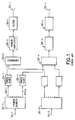
- Fig. 1 depicts a conventional multi phased array antenna system having multiple microwave radiating horns 33 connected to a respective transmission system.
- the antenna radiator 33 transmits a pattern which has a mainbeam and a series of lobes focused at differing solid angles which contribute to transmitting radio frequencies in a given direction.
- the term RF employed herein is considered particularly with respect to the "millimetre-wave" region of the RF spectrum (frequencies above 20 GHz).
- a phased array antenna system can both transmit and receive electromagnetic radiation from different angles.
- Typical phased array systems transmit and receive at frequencies selected from a frequency band in the range of between 300 Megahertz to 40 Gigahertz.
- Multibeam phased arrays are typically comprised of a multiplicity of individual beam forming transmission elements.
- the phased arrays are processed by combining the voltages from a plurality of beam forming signals that are individually phased, amplified, filtered and impressed on antenna elements, such as the radiator horns 33 of the prior art system of Fig. 1, to produce multiple beams in different directions.
- an RF beam 10-1 having a primary frequency f 1 is connected to a transmitting power divider 20-1, whose multiple outputs 24-1 through 24-n are connected to separate phase shift means 25.
- the outputs of the phase shift means 25 for different beams are combined in a combiner means 22, whose function is to combine properly phased signals for each beam which are assigned to particular radiating elements.
- a second RF beam 10-2 of another frequency f 2 is connected through similar circuit elements as RF beam 10-1 as shown in the prior art system of Fig. 1.
- the radio frequency beam phase and amplitude ultimately to be transmitted by the antenna are first delivered to the beam forming network that consists of a plurality of multiplexed power dividers such as divider 20 which provides a plurality of signals and couples a signal having a particular phase to one input of a multiplicity of inputs of a plurality of combiners such as combiner 22.
- each combiner receives signals at each transmission frequency, with appropriate phase angles from each of the plurality of power dividers, and combines these inputs to form a composite signal for the transmitted RF energy.
- the combined RF signals are coupled to the transmitting elements through power amplifiers 26, filters 30 and finally the radiator horns 33.
- phased array antenna systems that have a high degree of fidelity across all the radiators 33 is crucial to the success of most applications to which phased array systems are employed. This is accomplished through use advanced technologies in antenna design and processing circuitry.
- phased array antennas constructed from MMIC chip technology at each antenna subsystem element(forming the so-called active array antenna) allow for very large effective-radiated-power levels and large system redundancy.
- newer technologies emerge it becomes feasible to extend the transmission frequencies into the tens of gigahertz.
- existing fabrication and electronic designs do not permit the close proximity of elements required at such newer higher frequencies.
- an 8-beam phased array having 100 elements in the array would require eight 100-way power dividers, 800 phase shifters, and 100 eight-way combiners, plus 100 power amplifiers, filters and radiating elements. So large a number of components in the aggregate cannot feasibly be accommodated in the small space required in and about the antenna section of the conventional system, especially with the myriad of waveguides required for the many interconnections.
- Phased array antennas are extremely expensive to produce, in part, because of the large number of interconnections for the signal distribution and phase control.
- the problems of system cost are compounded in multibeam phased array applications.
- transmission frequencies for multibeam phased array systems are pushed to new limits, new and novel electronic design techniques must follow.
- the present invention provides a system that allows increases in the frequency of transmission of a multibeam RF transmission antenna system without being limited by physical space requirements.
- the present invention seeks to provide a method and an apparatus for a multibeam phased array antenna transmission employing heterodyning to produce the required transmission signals with appropriate phase shift, thereby reducing the effect of certain space constraints in the confined area of the transmitter, as higher and higher frequencies of transmission are employed.
- the present invention also seeks to increase the transmission frequency of a phased array antenna system by utilizing an intermediate frequency in some stages of the antenna subsystem and therefore alleviate the space constraints otherwise imposed by the higher frequency.
- RF signals at an intermediate frequency comprise the signal frequency for a beam forming network which provides input to a multiplexed power divider.
- the use of a lower frequency in the power divider, phaser and combiner stages thereby permits the use of conventionally sized components.
- the power divider outputs a signal having a desired phase to an input at each of a number of multiplexed combiners, the outputs of which are fed to mixing devices which then shift the input frequency to a higher frequency for transmission.
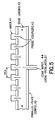
- this technique is known as heterodyning where the lower frequency is mixed with a higher frequency in a non-linear device to produce frequencies both higher and lower than the original frequencies.
- heterodyning is accomplished through a non-linear device referred to as a mixer which produces side band frequencies, one of which is at the desired frequency of transmission.
- Each mixer thus requires a local oscillator signal, which is at a frequency which is the difference between the input frequency and the desired output frequency.
- the present invention therefore is a method and apparatus for a phased array antenna system having adjustable phase and amplitude feeding coefficients.
- the invention first provides for a plurality of RF beams at a primary, intermediate frequency, as input to a plurality of power dividers, the outputs of which are coupled to a plurality of associated phase shifters whose outputs are coupled to a plurality of associated combiners.
- the outputs of the combiners which are at the primary frequency then are mixed or heterodyned with a higher reference frequency to produce a desired set of signals at the transmitting frequency.
- the use of the mixer allows a lower frequency to be used in the stages leading up to the power amplifier and, until that stage, permits the use of components, the physical size of which are not constrained by the physical space required for their implementation at the transmission frequency.
- an apparatus for a multiple-beam millimetre-wave phased array system comprising signal forming circuit network means responsive to a plurality of input beam signals having a primary lower RF frequency for dividing, phase shifting and combining the signals into a plurality of output signals at the lower frequency, a local oscillator means, and a heterodyning means connected to each of the circuit network output signals and to the local oscillator means for providing a plurality of output signals at a desired output frequency higher than the primary frequency.
- an apparatus for a multiple-beam millimetre-wave phase array antenna system comprising a plurality of power divider circuit means, each connected to a separate one of a plurality of primary frequency RF input beam signals for dividing each of the input beam signals into a plurality of divided output signals, at the primary frequency, a plurality of MMIC phase shift circuit means each connected to a separate one of the plurality of divided output signals of the power divider circuit means to provide phase shifted output signals at the primary frequency, a plurality of combiner circuit means connected to the plurality of MMIC phase shift circuit means for combining together selected ones of the shifted output signals from the phase shift circuit means, a local oscillator means, and a plurality of mixer circuit means connected to the combiner circuit means and to the local oscillator means for heterodyning the primary frequency signals from the combiner means with the local oscillator frequency to convert the primary frequency output signals from the combiner circuit to desired output frequencies higher than the primary frequency.
- a method for transmitting a multiple-beam millimetre-wave phased array output signals comprising the steps of dividing each of a plurality of primary frequency RF input beam signals into plurality of divided primary frequency signals, shifting the phase of the divided signals, combining selected ones of the phase shifted divided primary frequency signals together, to provide a plurality of combined phase shifted primary frequency signals, and heterodyning all of the combined primary frequency phase shifted signals with a local oscillator frequency signal to convert the primary frequency of the combined signals to desired higher frequency output frequency signals.
- the present invention is an apparatus for a phased array antenna system providing multiple beams which are independently steerable for transmission or reception, having adjustable phase and amplitude feeding coefficients comprising: a means for generating a reference frequency; a means for generating a plurality of primary frequency RF beam signals; dividing each of the beams and coupling the divided beams to a phase shifter after which the shifted beam signals are combined and mixed with a local oscillator at the reference frequency to produce a desired transmitting frequency.
- blocks and associated arrows represent functions of the process according to the present invention which may be implemented as electrical circuits typically utilizing MMIC, waveguide, stripline technology and associated wires or data busses, which transport electrical signals.
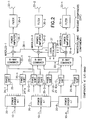
- n-element phased array system consisting of a beam forming network ("BFN") wherein "m" RF beams are inputted to a set of power dividers 20-1 through 20-m, phase shift means 25-1 through 25-n, combiners 22-1 through 22-n, a local oscillator 27, power amplifiers 26-1 through 26-n, filters 30-1 through 30-n and radiators 33-1 through 33-n.
- Each of the power dividers such as the power divider 20-1, supplies an output signal having an amplitude and phase to a phase shift means 25-1 which shifts the phase a predetermined amount.
- phase shift means n there are as many phase shift means n on each power divider 20-1 through 20-n output as there are array elements 1 through n.
- phase shift means 25-1 through 25-n for the power divider 20-1, and the embodiment of Fig. 2 will include a total of 8n phase shift means.
- Combiner means 22-1 through combiner means 22-n each include eight combiner circuits for a total of 8n, and each fed one phase shifted signal from one of the outputs of phase shift means 25-1 through 25-8n.
- the combiner means 22-1 through 22-n are coupled to mixers 23-1 through 23-n, which are supplied from a common local oscillator 27; these produce the beam signal at the higher frequency with proper phases to be transmitted for each beam.
- the typical frequency of the primary frequency is in the S-band or C-band whereas the transmitted frequency is upwards of 20 GHz.
- Typically a 6 GHz primary frequency signal mixed with a 14 GHz reference signal will produce a 20 GHz transmission signal.
- the local oscillator 27 outputs 28-1 through 28-n are mixed with the signals from the combiner means 22-1 through 22-n, respectively and the resulting signals are then fed to power amplifiers 26-1 through 26-n.
- the power amplifiers 26-1 through 26-n are then fed to corresponding filters 30-1 through 30-n which feed transmission antenna radiation horns 33-1 through 33-n.
- Fig. 3 shows a typical stripline beam forming network, such as would form beam 1, of the type that may be employed in the present invention.
- Input port 29 receives the primary signal such as beam 1 of Fig. 2 which is divided through power divider 20 and phase shifted through phase shift means 25.
- the phase shift means in the preferred embodiment are based on MMIC technology.
- the phase shift means 25 output is coupled to power combiner means 22 and presented at the combined element outputs 31.
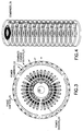
- Fig. 4 illustrates an embodiment of a multiple beam forming network implemented as a stripline stack of individual beam forming networks 39.
- the output elements are coupled to a separate layer individual mixers and to the local oscillator 27.
- Fig. 5 illustrates an embodiment of a local oscillator distribution network.
- the oscillator 27 in Fig. 5 may be implemented in MMIC technology.
- the heterodyning circuit is comprised of a parallel plate local oscillator distribution circuit 45, edge loading 42, and a series of mixers 41.
- the local oscillator reference signal is provided by way of a coaxial cable connected to input port 44.
- the probe coupler 43 couples the higher frequency output of the local oscillator 27 to the individual mixers 41, whose heterodyned outputs are fed by waveguide, with appropriate filtering, to the power amplifiers 26.
- the present invention also provides a method for a phased array antenna system having adjustable phase and amplitude feeding coefficients comprising the steps of generating a reference frequency, coupling a plurality of primary frequency RF beams to a plurality of corresponding power dividers, coupling each power divided beam to a plurality of corresponding phase shifters whose output are coupled to a plurality of associated means to combine signals from associated phase shifted beams and heterodyning the combined output beams at the primary frequency and the lower reference frequency to produce a desired transmitting frequency.
- a feature of the invention is that it permits the use of conventional lower-frequency stripline or printed-circuit components for the network portion of the array, plus MMIC phasers, followed by individual mixers for each element to heterodyne the primary frequency signals to the desired output frequencies, followed by individual millimetre-wave power amplifiers, filters and radiating elements.
- the invention affords the advantage of using conventional lower-frequency beam-forming circuitry, which is easier to build, less costly, and avoids the size restrictions of higher-frequency circuits. Interconnections to the closely-spaced millimetre-wave components can be by means of low-loss coaxial cables, thus allowing more space for the conventional circuitry.
Landscapes
- Variable-Direction Aerials And Aerial Arrays (AREA)
Applications Claiming Priority (2)
| Application Number | Priority Date | Filing Date | Title |
|---|---|---|---|
| US908484 | 1978-05-22 | ||
| US08/908,484 US5977910A (en) | 1997-08-07 | 1997-08-07 | Multibeam phased array antenna system |
Publications (2)
| Publication Number | Publication Date |
|---|---|
| EP0896383A2 true EP0896383A2 (de) | 1999-02-10 |
| EP0896383A3 EP0896383A3 (de) | 2000-07-12 |
Family
ID=25425880
Family Applications (1)
| Application Number | Title | Priority Date | Filing Date |
|---|---|---|---|
| EP98306333A Withdrawn EP0896383A3 (de) | 1997-08-07 | 1998-08-07 | Phasengesteuertes Mehrstrahl-Antennensystem |
Country Status (3)
| Country | Link |
|---|---|
| US (1) | US5977910A (de) |
| EP (1) | EP0896383A3 (de) |
| JP (1) | JPH11127021A (de) |
Cited By (13)
| Publication number | Priority date | Publication date | Assignee | Title |
|---|---|---|---|---|
| EP1043803A3 (de) * | 1999-04-09 | 2001-06-27 | TRW Inc. | Direkt strahlende Gruppenantenne mit mehreren abtastenden Keulen und Verfahren für ihre Verwendung |
| EP1109252A3 (de) * | 1999-12-13 | 2002-08-28 | Space Systems / Loral, Inc. | Im Spritzguss hergestelltes phasengesteuertes Gruppenantennensystem |
| AU2002337354B2 (en) * | 2001-11-14 | 2006-06-22 | Quintel Technology Limited | Antenna system |
| WO2011161198A1 (en) * | 2010-06-23 | 2011-12-29 | Astrium Limited | An antenna |
| WO2012168878A1 (en) * | 2011-06-06 | 2012-12-13 | Poynting Holdings Limited | Multi-beam multi-radio antenna |
| CN103094654A (zh) * | 2013-01-28 | 2013-05-08 | 零八一电子集团有限公司 | 双波束集成馈电网络 |
| WO2013176930A1 (en) * | 2012-05-23 | 2013-11-28 | Intel Corporation | Multi-element antenna beam forming configurations for millimeter wave systems |
| WO2015078404A1 (zh) * | 2013-11-28 | 2015-06-04 | 华为技术有限公司 | 一种天线及无线信号发送、接收方法 |
| WO2015160894A1 (en) * | 2014-04-15 | 2015-10-22 | Space Systems/Loral, Llc | Broadband satellite payload architecture |
| US9537546B2 (en) | 2011-12-08 | 2017-01-03 | Intel Corporation | Implementing MIMO in mmWave wireless communication systems |
| US20180321369A1 (en) * | 2015-11-12 | 2018-11-08 | Israel Aerospace Industries Ltd. | Integrated electromagnetic seeker |
| CN114325603A (zh) * | 2021-12-17 | 2022-04-12 | 中国航天科工集团八五一一研究所 | 宽带多波束相控阵前端 |
| CN115411527A (zh) * | 2022-04-27 | 2022-11-29 | 江苏亨鑫科技有限公司 | 一种应用于融合基站天线的一体化馈电网络的装置 |
Families Citing this family (23)
| Publication number | Priority date | Publication date | Assignee | Title |
|---|---|---|---|---|
| JPH10336087A (ja) * | 1997-05-30 | 1998-12-18 | Kyocera Corp | 最大比合成送信ダイバーシティ装置 |
| US6621468B2 (en) | 2000-09-22 | 2003-09-16 | Sarnoff Corporation | Low loss RF power distribution network |
| FR2828031B1 (fr) * | 2001-07-30 | 2003-10-17 | Nortel Networks Ltd | Station de base de radiocommunication a diagramme de rayonnement variable |
| US6906665B1 (en) | 2002-11-15 | 2005-06-14 | Lockheed Martin Corporation | Cluster beam-forming system and method |
| US7109918B1 (en) * | 2003-05-23 | 2006-09-19 | The United States Of America As Represented By The Secretary Of The Navy | Nonlinear beam forming and beam shaping aperture system |
| US7392011B1 (en) * | 2005-05-31 | 2008-06-24 | Lockheed Martin Corporation | Method and system for flexibly distributing power in a phased array antenna system |
| KR100971096B1 (ko) * | 2005-06-09 | 2010-07-20 | 맥도널드, 디트윌러 앤드 어소시에이츠 엘티디. | 경량의 공간-피딩된 능동 위상 어레이 안테나 시스템 |
| US7629918B2 (en) * | 2005-12-15 | 2009-12-08 | Raytheon Company | Multifunctional radio frequency directed energy system |
| WO2008041222A2 (en) * | 2006-10-03 | 2008-04-10 | Beam Networks Ltd. | Phased shifted oscilator and antenna |
| WO2015184871A1 (en) * | 2014-06-05 | 2015-12-10 | Commscope Technologies Llc | Independent azimuth patterns for shared aperture array antenna |
| US20160218429A1 (en) * | 2015-01-23 | 2016-07-28 | Huawei Technologies Canada Co., Ltd. | Phase control for antenna array |
| CN109314555A (zh) * | 2016-06-16 | 2019-02-05 | 瑞典爱立信有限公司 | 用于扇区化的灵活模拟架构 |
| WO2018231215A1 (en) | 2017-06-14 | 2018-12-20 | Higher Ground Llc | A spatial router with dynamic queues |
| US10742309B2 (en) | 2017-06-14 | 2020-08-11 | Higher Ground Llc | Spatial router with dynamic queues |
| US11112491B2 (en) | 2017-06-29 | 2021-09-07 | Rockley Photonics Limited | Optical scanner and detector |
| US10677989B2 (en) | 2017-07-05 | 2020-06-09 | Rockley Photonics Limited | Reconfigurable spectroscopy system |
| WO2019190412A1 (en) * | 2018-03-29 | 2019-10-03 | Agency For Science, Technology And Research | Beam steerable antenna system, method of manufacturing thereof and method of beam steering an antenna array |
| JP6978688B2 (ja) * | 2018-03-29 | 2021-12-08 | 日本電信電話株式会社 | 無線通信装置及び無線通信方法 |
| US10944477B2 (en) | 2018-06-29 | 2021-03-09 | California Institute Of Technology | Multi-beam optical phased array |
| US10739256B1 (en) * | 2019-03-29 | 2020-08-11 | Rockley Photonics Limited | Spectroscopy system with beat component |
| US11471544B2 (en) * | 2020-05-12 | 2022-10-18 | Yoram Palti | Using a steerable beam of RF energy to eliminate viruses and/or bacteria from a volume of air |
| US12047051B2 (en) * | 2020-07-16 | 2024-07-23 | Qualcomm Incorporated | Matching network with tunable notch filter |
| CN119766155A (zh) * | 2024-12-20 | 2025-04-04 | 苏州莱尔微波技术有限公司 | 一种混频器阵列 |
Family Cites Families (7)
| Publication number | Priority date | Publication date | Assignee | Title |
|---|---|---|---|---|
| US3611381A (en) * | 1968-11-01 | 1971-10-05 | Boeing Co | Pilot normalized multibeam directionally selective array system |
| US4178100A (en) * | 1978-03-29 | 1979-12-11 | Nasa | Distributed-switch Dicke radiometers |
| US4652879A (en) * | 1985-02-11 | 1987-03-24 | Eaton Corporation | Phased array antenna system to produce wide-open coverage of a wide angular sector with high directive gain and strong capability to resolve multiple signals |
| US5179386A (en) * | 1986-08-21 | 1993-01-12 | Rudish Ronald M | Cylindrical phased array antenna system to produce wide open coverage of a wide angular sector with high directive gain and strong capability to resolve multiple signals |
| US4977382A (en) * | 1988-08-23 | 1990-12-11 | Pacific Monolithics | Vector modulator phase shifter |
| US4973971A (en) * | 1989-12-18 | 1990-11-27 | Allied-Signal Inc. | Broadband circular phased array antenna |
| US5642358A (en) * | 1994-04-08 | 1997-06-24 | Ericsson Inc. | Multiple beamwidth phased array |
-
1997
- 1997-08-07 US US08/908,484 patent/US5977910A/en not_active Expired - Lifetime
-
1998
- 1998-08-07 EP EP98306333A patent/EP0896383A3/de not_active Withdrawn
- 1998-08-07 JP JP10224363A patent/JPH11127021A/ja active Pending
Cited By (21)
| Publication number | Priority date | Publication date | Assignee | Title |
|---|---|---|---|---|
| EP1043803A3 (de) * | 1999-04-09 | 2001-06-27 | TRW Inc. | Direkt strahlende Gruppenantenne mit mehreren abtastenden Keulen und Verfahren für ihre Verwendung |
| EP1109252A3 (de) * | 1999-12-13 | 2002-08-28 | Space Systems / Loral, Inc. | Im Spritzguss hergestelltes phasengesteuertes Gruppenantennensystem |
| AU2002337354B2 (en) * | 2001-11-14 | 2006-06-22 | Quintel Technology Limited | Antenna system |
| US7230570B2 (en) | 2001-11-14 | 2007-06-12 | Quintel Technology Limited | Antenna system |
| US8897403B2 (en) | 2010-06-23 | 2014-11-25 | Astrium Limited | Antenna |
| WO2011161198A1 (en) * | 2010-06-23 | 2011-12-29 | Astrium Limited | An antenna |
| EP2403067A1 (de) * | 2010-06-23 | 2012-01-04 | Astrium Limited | Antenne |
| WO2012168878A1 (en) * | 2011-06-06 | 2012-12-13 | Poynting Holdings Limited | Multi-beam multi-radio antenna |
| US9407008B2 (en) | 2011-06-06 | 2016-08-02 | Poynting Antennas (Proprietary) Limited | Multi-beam multi-radio antenna |
| US9537546B2 (en) | 2011-12-08 | 2017-01-03 | Intel Corporation | Implementing MIMO in mmWave wireless communication systems |
| WO2013176930A1 (en) * | 2012-05-23 | 2013-11-28 | Intel Corporation | Multi-element antenna beam forming configurations for millimeter wave systems |
| US9444140B2 (en) | 2012-05-23 | 2016-09-13 | Intel Corporation | Multi-element antenna beam forming configurations for millimeter wave systems |
| CN103094654B (zh) * | 2013-01-28 | 2015-03-04 | 零八一电子集团有限公司 | 双波束集成馈电网络 |
| CN103094654A (zh) * | 2013-01-28 | 2013-05-08 | 零八一电子集团有限公司 | 双波束集成馈电网络 |
| WO2015078404A1 (zh) * | 2013-11-28 | 2015-06-04 | 华为技术有限公司 | 一种天线及无线信号发送、接收方法 |
| WO2015160894A1 (en) * | 2014-04-15 | 2015-10-22 | Space Systems/Loral, Llc | Broadband satellite payload architecture |
| US10270524B2 (en) | 2014-04-15 | 2019-04-23 | Space Systems/Loral, Llc | Broadband satellite payload architecture |
| US20180321369A1 (en) * | 2015-11-12 | 2018-11-08 | Israel Aerospace Industries Ltd. | Integrated electromagnetic seeker |
| CN114325603A (zh) * | 2021-12-17 | 2022-04-12 | 中国航天科工集团八五一一研究所 | 宽带多波束相控阵前端 |
| CN115411527A (zh) * | 2022-04-27 | 2022-11-29 | 江苏亨鑫科技有限公司 | 一种应用于融合基站天线的一体化馈电网络的装置 |
| CN115411527B (zh) * | 2022-04-27 | 2023-08-04 | 江苏亨鑫科技有限公司 | 一种应用于融合基站天线的一体化馈电网络的装置 |
Also Published As
| Publication number | Publication date |
|---|---|
| EP0896383A3 (de) | 2000-07-12 |
| JPH11127021A (ja) | 1999-05-11 |
| US5977910A (en) | 1999-11-02 |
Similar Documents
| Publication | Publication Date | Title |
|---|---|---|
| US5977910A (en) | Multibeam phased array antenna system | |
| EP0600715B1 (de) | Aktive phasengesteuerte Sende-Gruppenantenne | |
| US5870063A (en) | Spacecraft with modular communication payload | |
| US6232920B1 (en) | Array antenna having multiple independently steered beams | |
| US6169513B1 (en) | Thinned multiple beam phased array antenna | |
| EP0665607B1 (de) | Aktive phasengesteuerte Sende-Gruppenantenne mit ungleichmässiger Amplitudenverteilung | |
| US5952964A (en) | Planar phased array antenna assembly | |
| US6340948B1 (en) | Antenna system | |
| EP0398555B1 (de) | Leichte und flache phasengesteuerte Gruppenantenne mit elektromagnetisch gekoppelten integrierten Untergruppen | |
| EP4135125B1 (de) | Phasengesteuertes gruppenantennensystem | |
| US6246364B1 (en) | Light-weight modular low-level reconfigurable beamformer for array antennas | |
| CN106602265B (zh) | 波束成形网络及其输入结构、输入输出方法及三波束天线 | |
| US20020140616A1 (en) | Ultra-wideband multi-beam adaptive antenna | |
| JP2000244224A (ja) | マルチビームアンテナ及びアンテナシステム | |
| WO2007103589A2 (en) | Multi-beam tile array module for phased array systems | |
| US5333001A (en) | Multifrequency antenna array | |
| US6072432A (en) | Hybrid power tapered/space tapered multi-beam antenna | |
| So et al. | Staircase array antenna with stacked butler matrix for concurrent multi-beams | |
| Gorski et al. | Developments on phased array for low-cost, high frequency applications | |
| Kim et al. | A heterodyne-scan phased-array antenna | |
| WO2021106003A1 (en) | Metal waveguide connected antenna array | |
| EP4379953B1 (de) | Zirkularpolarisiertes antennengruppenmodul und drahtlose kommunikationsvorrichtung | |
| JPH0435301A (ja) | アクティブアレイアンテナ | |
| Tan et al. | A new concept for multi-beam phased array | |
| Lisi et al. | An active array antenna at X-band for spaceborne SAR applications: system design tradeoffs |
Legal Events
| Date | Code | Title | Description |
|---|---|---|---|
| PUAI | Public reference made under article 153(3) epc to a published international application that has entered the european phase |
Free format text: ORIGINAL CODE: 0009012 |
|
| AK | Designated contracting states |
Kind code of ref document: A2 Designated state(s): DE FR GB IT |
|
| AX | Request for extension of the european patent |
Free format text: AL;LT;LV;MK;RO;SI |
|
| PUAL | Search report despatched |
Free format text: ORIGINAL CODE: 0009013 |
|
| AK | Designated contracting states |
Kind code of ref document: A3 Designated state(s): AT BE CH CY DE DK ES FI FR GB GR IE IT LI LU MC NL PT SE |
|
| AX | Request for extension of the european patent |
Free format text: AL;LT;LV;MK;RO;SI |
|
| 17P | Request for examination filed |
Effective date: 20000816 |
|
| AKX | Designation fees paid |
Free format text: DE FR GB IT |
|
| STAA | Information on the status of an ep patent application or granted ep patent |
Free format text: STATUS: THE APPLICATION HAS BEEN WITHDRAWN |
|
| 18W | Application withdrawn |
Effective date: 20030710 |