EP0896173A2 - Dichtungsvorrichtung - Google Patents
Dichtungsvorrichtung Download PDFInfo
- Publication number
- EP0896173A2 EP0896173A2 EP98111390A EP98111390A EP0896173A2 EP 0896173 A2 EP0896173 A2 EP 0896173A2 EP 98111390 A EP98111390 A EP 98111390A EP 98111390 A EP98111390 A EP 98111390A EP 0896173 A2 EP0896173 A2 EP 0896173A2
- Authority
- EP
- European Patent Office
- Prior art keywords
- sealing
- socket
- sliding
- space
- moulded
- Prior art date
- Legal status (The legal status is an assumption and is not a legal conclusion. Google has not performed a legal analysis and makes no representation as to the accuracy of the status listed.)
- Withdrawn
Links
Images


Classifications
-
- F—MECHANICAL ENGINEERING; LIGHTING; HEATING; WEAPONS; BLASTING
- F16—ENGINEERING ELEMENTS AND UNITS; GENERAL MEASURES FOR PRODUCING AND MAINTAINING EFFECTIVE FUNCTIONING OF MACHINES OR INSTALLATIONS; THERMAL INSULATION IN GENERAL
- F16L—PIPES; JOINTS OR FITTINGS FOR PIPES; SUPPORTS FOR PIPES, CABLES OR PROTECTIVE TUBING; MEANS FOR THERMAL INSULATION IN GENERAL
- F16L21/00—Joints with sleeve or socket
- F16L21/02—Joints with sleeve or socket with elastic sealing rings between pipe and sleeve or between pipe and socket, e.g. with rolling or other prefabricated profiled rings
- F16L21/03—Joints with sleeve or socket with elastic sealing rings between pipe and sleeve or between pipe and socket, e.g. with rolling or other prefabricated profiled rings placed in the socket before connection
-
- F—MECHANICAL ENGINEERING; LIGHTING; HEATING; WEAPONS; BLASTING
- F16—ENGINEERING ELEMENTS AND UNITS; GENERAL MEASURES FOR PRODUCING AND MAINTAINING EFFECTIVE FUNCTIONING OF MACHINES OR INSTALLATIONS; THERMAL INSULATION IN GENERAL
- F16L—PIPES; JOINTS OR FITTINGS FOR PIPES; SUPPORTS FOR PIPES, CABLES OR PROTECTIVE TUBING; MEANS FOR THERMAL INSULATION IN GENERAL
- F16L21/00—Joints with sleeve or socket
- F16L21/02—Joints with sleeve or socket with elastic sealing rings between pipe and sleeve or between pipe and socket, e.g. with rolling or other prefabricated profiled rings
- F16L21/035—Joints with sleeve or socket with elastic sealing rings between pipe and sleeve or between pipe and socket, e.g. with rolling or other prefabricated profiled rings placed around the spigot end before connection
-
- F—MECHANICAL ENGINEERING; LIGHTING; HEATING; WEAPONS; BLASTING
- F16—ENGINEERING ELEMENTS AND UNITS; GENERAL MEASURES FOR PRODUCING AND MAINTAINING EFFECTIVE FUNCTIONING OF MACHINES OR INSTALLATIONS; THERMAL INSULATION IN GENERAL
- F16L—PIPES; JOINTS OR FITTINGS FOR PIPES; SUPPORTS FOR PIPES, CABLES OR PROTECTIVE TUBING; MEANS FOR THERMAL INSULATION IN GENERAL
- F16L25/00—Constructive types of pipe joints not provided for in groups F16L13/00 - F16L23/00 ; Details of pipe joints not otherwise provided for, e.g. electrically conducting or insulating means
- F16L25/0018—Abutment joints
Definitions
- the present invention relates to a sealing device for sealing a joint between two elements, for example two pipe end portions.
- a previously known sealing device of this kind comprises a space positioned between the elements and defined by two sealing surfaces facing each other and positioned on the two elements and a sealing element consisting of elastic material and compressed in the space between the sealing surfaces.
- the sealing element is introducable into the space while a sliding action takes place between one or more sliding surfaces arranged on the sealing element on one hand and the sealing surface or the sealing surfaces of the sealing surfaces on the other hand to the position in which the sealing element is compressed in the space between the sealing surfaces.
- the elements and thereby the sealing surfaces thereof consist of a relatively coarse material, for example concrete, it is necessary to take special measures for making it possible for the sealing surfaces and the sliding surfaces of the sealing elements to slide against each other without any problems.
- sealing ring of this kind When using a sealing ring of this kind the sliding does not take place between the sealing ring and the sealing surface of the socket or the spigot end but inside the sealing ring between the sliding skin of the sealing ring and the main body of the sealing ring, the sliding skin being without sliding carried along by the sealing surface engaging the sliding skin.
- a sealing ring of this kind the lubricant is applied in a pocket positioned between the sliding skin of the sealing ring and the main body thereof which makes it possible to apply the lubricant in connection with the manufacturing of the sealing ring, and this provides that it is not necessary to apply a lubricant in connection with the pipe jointing.
- a drawback of sealing rings of this kind is that they are complicated to manufacture and therefore relatively expensive.
- a further drawback is that it is in connection with the pipe jointing often necessary to adjust the position of the sliding skin before the pipe jointing is started.
- the object of the invention is to provide a sealing device which lacks the above drawbacks.
- the sealing device is characterized in that the sliding surface or the sliding surfaces of the sealing element and/or the sealing surface or the sealing surfaces intended to cooperate with said sliding surface or said sliding surfaces are at least partially provided with fibre flock applied to said surfaces.
- fibre flock applied to the sliding surfaces and/or the sealing surfaces in an excellent way acts as a lubricant and makes it unnecessary to apply a lubricant in connection with the pipe jointing or to provide the sealing element with a sliding skin.
- the fibre flock consists of textile fibres, for example synthetic fibres of polyamide, having a length of between 0,5 and 5 mm and preferably comprising 50 - 300 fibres per square millimetre.
- the fibre flock is suitably connected with the surfaces by means of an adhesive, for example a resin adhesive of the two-component type.
- the sealing element is moulded into the element forming one of the sealing surfaces
- it can be suitable to provide also the surface of the sealing element which is moulded into the element provided with said sealing surface with fibre flock applied thereto, in order to improve the binding between the sealing element and the element into which the sealing element is moulded.
- Fig. 1a shows a section of a joint between two concrete elements 2 and 4, for example two concrete plates each having a sealing surface 6 and 8, respectively.
- the sealing surfaces 6 and 8 face each other and define together a space 10 between the sealing surfaces 6 and 8.
- a sealing element 12 which is compressed between the sealing surfaces 6 and 8 and is formed as a bead.
- the sealing bead 12 consists of elastic rubber material 12 and a reinforcing element 18 vulcanized into the elastic material, the reinforcing element consisting of plastic or any other material which is rigid in relation to the elastic rubber material 16.
- the sealing bead 12 has layers of fibre flock 20 applied onto said side surfaces.
- the fibre flock 20 consists of textile fibres, for example synthetic fibres of polyamide, having a length for example 3 mm.
- the fibre flock 20 includes a relatively large number of fibres per square mm of the side surfaces of the sealing bead 12, for example 150 - 300 fibres per square mm.
- the fibre flock 20 has the object of providing a sliding agent or lubricant when providing the joint between the concrete elements 2 and 4 by introducing the sealing bead 12 into the space 10 between the sealing surfaces 6 and 8.
- the sealing bead 12 is forced into the space 12 from the upper end of the space 10, while the side surfaces of the sealing bead 12 slide against the sealing surfaces 6 and 8 of the space 10.
- the sealing bead 12 is introduced into the space 10 the sealing bead is compressed, so that the side surfaces of the sealing bead 12 are in a sealing way forced against the sealing surfaces 6 and 8.
- the usual application of a lubricant onto the side surfaces of the sealing bead or onto the sealing surfaces 6 and 8 can be eliminated which is otherwise necessary for making it possible for the sealing bead 12 to slide against the sealing surfaces 6 and 8 in a correct way.
- the introduction is facilitated by the existence of the reinforcing element 18 which prevents that the sealing bead 12 is at the introduction compressed in the vertical direction.
- the fibre flock 20 is bound to the side surfaces of the sealing bead 12 by means of an adhesive, for example a resin adhesive of two-component type.
- an adhesive for example a resin adhesive of two-component type.
- the application of the fibre flock is suitably conducted by means of a conventional technique according to which the sealing surfaces of the sealing bead are initially provided with an adhesive whereupon electrically charged fibres are supplied to the adhesive and thereby get stuck and bound.
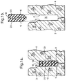
- Fig. 2a shows an axial section of a joint between the end portions of two concrete pipes, said end portions forming a socket 22 and a spigot end 24.
- the socket 22 has an inner, substantially cylindrical sealing surface 26, and the spigot end has an outer, also substantially cylindrical sealing surface 28.
- the sealing surfaces 26 and 28 are substantially concentric with each other and define an annular space 30 in which a sealing ring 32 is compressed while being forced against the sealing surfaces 26 and 28.
- the sealing ring 32 has a support portion 34 resting on a shoulder 36 on the spigot end 24 and has further a sealing projection 38, which, as appears from Fig. 2, prior to the pipe jointing forms a substantially conical sliding surface 40.
- a layer 42 of fibre flock is applied to the sliding surface 40, the fibre flock being of the same kind as the fibre flock layer 20 of the embodiment according to Figs. 1a and 1b.
- the sealing ring 32 Prior to the establishment of the pipe joint shown in Fig. 2a the sealing ring 32 is tensioned onto the spigot end 24 into the position shown in Fig. 2b, whereupon the sealing surfaces 26 and 28 are introduced one into the other to the position shown in Fig. 2 by introducing the spigot end 24 into the socket 22 in the axial direction of the socket and the spigot end, i.e. in a direction substantially parallel with the sealing surfaces 26 and 28.
- the inner corner 44 of the socket 22 will hit the conical sliding surface 40 of the sealing ring 32 for compressing the sealing projection 38 to the position shown in Fig. 2a while sliding against said conical sliding surface, the sealing ring 32 being in said position compressed between the sealing surfaces 26 and 28.
- the sliding against the conical surface 40 is made possible by the fact that the surface is provided with the layer 42 of fibre flock acting as a sliding agent or lubricant during the jointing movement. Because of the layer 42 of fibre flock there is not required the usual application of lubricant onto the sliding surface 40 of the sealing ring or the sealing surface 26 of the socket.
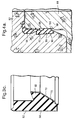
- Fig. 3a there is shown an axial section of a joint between a socket 52 and a spigot end 54 belonging to each of two pipe end portions consisting of concrete.
- the joint is sealed by means of a sealing device according to the invention comprising an inner, substantially cylindrical sealing surface 56 on the socket 52 and a substantially cylindrical sealing surface 58 on the spigot end 54 substantially concentric with the sealing surface of the socket.
- the sealing surfaces 56 and 58 define an annular space 60 between the socket and the spigot end, and in this space there is positioned a compressed sealing ring 62 engaging the sealing surfaces 56 and 58.
- the sealing ring 62 is connected with the sealing surface 56 of the socket by the fact that the sealing ring is partly moulded into the socket 52 at said surface thereof.
- the moulding of the sealing ring 62 into the socket has in a way known per se been provided in connection with the moulding of the concrete pipe which includes the socket 52.
- the surface portion of the sealing ring 62 which is moulded into the socket 52 is provided with a layer 64 of fibre flock applied to said surface portion.
- the fibre flock included in the layer 64 is bound to said surface portion of the sealing ring 62 by means of an adhesive.
- the fibre flock consists of textile fibres, for example synthetic fibres of polyamide, and the fibres can have a length of between 0,5 and 5 mm.
- the number of fibres per area unit can for example amount to between 50 and 300 fibres per square mm.
- the layer 64 consisting of fibre flock provides for an efficient binding of the sealing ring 62 to the concrete without the use of special retainer portions or the like on the sealing ring 62.
- the omission of such retainer portions is advantageous with regard to the fact that the retainer portions decrease the strength of the concrete of the socket 52.
- the joint between the socket 52 and the spigot end 54 is provided by the fact that the socket 52 and the spigot end 54 are, starting from the position shown in Fig. 3b, introduced one into the other in the axial direction, i.e. in a direction substantially parallel with the sealing surfaces 56 and 58.
- the outer edge 66 of the spigot end will hit a radially inwardly directed sealing portion 68 of the sealing ring 62 while sliding against the conical surface 70 of the sealing portion 68.
- the sliding surface 58 slides against the free inner surface of the sealing portion 68 of the sealing rings 62.
- the sealing portion of the sealing ring is at its inner surface provided with a layer 72 of a fibre flock applied to said surface.
- This fibre flock is suitably of the same kind as the fibre flock included in the layers 20 and 40 in the sealing device according to the invention described with reference to the above embodiments.
- the layer 72 of fibre flock provides that it is prior to the pipe jointing not necessary to apply a special lubricant onto the sealing surface 58 of the spigot end 54 or onto the sealing ring 62.
- the embodiment of the sealing device according to the invention shown in Figs. 4a and 4b is included in a joint between a socket 82 and a spigot end 84 belonging to the end portions of two concrete pipes.
- the socket 82 has a sealing surface 86 and the spigot end 84 has a sealing surface 88, the sealing surfaces being of substantially cylindrical shape and being concentric with each other for forming an annular space 90 between the socket 82 and the spigot end 84.
- a sealing ring 92 which is compressed between the sealing surfaces 86 and 88.
- the sealing ring 92 is formed in one piece with an annular element 94 which is positioned in the socket 82 axially inside the sealing ring 92.
- the annular unit consisting of the sealing ring 92 and the annular element 94 is moulded into the socket 82 at the inner surface thereof.
- the annular element 94 forms a deformable portion axially inside the sealing ring 92 which makes it unnecessary to use at the moulding a mould portion which is positioned axially inside the sealing ring 92 and must subsequently be removed.
- the sealing ring 92 as well as the annular element 92 have at the portion moulded into the concrete material of the socket 82 a layer 96 of fibre flock so as to improve the binding to the concrete in the same way as according to the embodiments of Figs. 3a, 3b and 3c which makes it possible to exclude special retainer elements from the sealing ring 92 and the annular element 94.
- the sealing ring 92 is at an inner, conical surface 100 provided with a layer 102 consisting of fibre flock of the same kind as the fibre flock of the embodiments of the sealing devices according to the invention described above.
- the sealing ring 92 takes a compressed, sealing position in the space between the sealing surfaces 86 and 88.
- the annular element 94 takes up the deformation of the sealing ring 92 and allows also a certain angular position between the spigot end 84 and the socket 82.
- the layer 102 consisting of fibre flock makes it possible to exclude the application of a lubricant prior to the connection of the spigot end 84 and the socket 82.
Landscapes
- Engineering & Computer Science (AREA)
- General Engineering & Computer Science (AREA)
- Mechanical Engineering (AREA)
- Gasket Seals (AREA)
- Joints With Sleeves (AREA)
- Lining And Supports For Tunnels (AREA)
- Joints With Pressure Members (AREA)
Applications Claiming Priority (2)
| Application Number | Priority Date | Filing Date | Title |
|---|---|---|---|
| SE9702864 | 1997-08-05 | ||
| SE9702864A SE9702864L (sv) | 1997-08-05 | 1997-08-05 | Tätningsanordning |
Publications (2)
| Publication Number | Publication Date |
|---|---|
| EP0896173A2 true EP0896173A2 (de) | 1999-02-10 |
| EP0896173A3 EP0896173A3 (de) | 1999-12-15 |
Family
ID=20407877
Family Applications (1)
| Application Number | Title | Priority Date | Filing Date |
|---|---|---|---|
| EP98111390A Withdrawn EP0896173A3 (de) | 1997-08-05 | 1998-06-20 | Dichtungsvorrichtung |
Country Status (5)
| Country | Link |
|---|---|
| EP (1) | EP0896173A3 (de) |
| JP (1) | JPH11132335A (de) |
| BR (1) | BR9806524A (de) |
| CA (1) | CA2244547A1 (de) |
| SE (1) | SE9702864L (de) |
Cited By (3)
| Publication number | Priority date | Publication date | Assignee | Title |
|---|---|---|---|---|
| EP2682535A3 (de) * | 2012-07-04 | 2014-08-13 | Theodor Cordes GmbH & Co. KG | Rohrverbindung mit verstärktem Dichtungsring, sowie Dichtungsring dafür |
| WO2017215715A1 (de) * | 2016-06-15 | 2017-12-21 | Dätwyler Sealing Technologies Deutschland Gmbh | Dichtungsprofil zur einbettung in ein formteil aus aushärtbarem material |
| DE102017116093A1 (de) * | 2017-07-18 | 2019-01-24 | Dätwyler Sealing Technologies Deutschland Gmbh | Dichtungsprofil zur Einbettung in ein Formteil aus aushärtbarem Material |
Citations (1)
| Publication number | Priority date | Publication date | Assignee | Title |
|---|---|---|---|---|
| SE403650B (sv) | 1978-01-11 | 1978-08-28 | Forsheda Gummifabriks Ab | Tetningsring for avtetning av spalten mellan tva axiellt sammanforbara tetningsytor och sett att framstella nemnda ring |
Family Cites Families (2)
| Publication number | Priority date | Publication date | Assignee | Title |
|---|---|---|---|---|
| FR2701527B1 (fr) * | 1993-02-16 | 1995-05-12 | Tuyaux Bonna | Joint d'étanchéité, notamment destiné à établir une étanchéité entre deux tuyaux ou analogues mutuellement emboîtés, et tuyau ou analogue comportant un tel joint. |
| DE9415228U1 (de) * | 1994-09-20 | 1996-02-15 | Wedekind Denso Chemie | Dichtungsanordnung zum Abdichten von Bauwerksfugen |
-
1997
- 1997-08-05 SE SE9702864A patent/SE9702864L/ not_active IP Right Cessation
-
1998
- 1998-06-20 EP EP98111390A patent/EP0896173A3/de not_active Withdrawn
- 1998-08-03 BR BR9806524-6A patent/BR9806524A/pt not_active Application Discontinuation
- 1998-08-04 CA CA 2244547 patent/CA2244547A1/en not_active Abandoned
- 1998-08-05 JP JP10222048A patent/JPH11132335A/ja active Pending
Patent Citations (1)
| Publication number | Priority date | Publication date | Assignee | Title |
|---|---|---|---|---|
| SE403650B (sv) | 1978-01-11 | 1978-08-28 | Forsheda Gummifabriks Ab | Tetningsring for avtetning av spalten mellan tva axiellt sammanforbara tetningsytor och sett att framstella nemnda ring |
Cited By (8)
| Publication number | Priority date | Publication date | Assignee | Title |
|---|---|---|---|---|
| EP2682535A3 (de) * | 2012-07-04 | 2014-08-13 | Theodor Cordes GmbH & Co. KG | Rohrverbindung mit verstärktem Dichtungsring, sowie Dichtungsring dafür |
| WO2017215715A1 (de) * | 2016-06-15 | 2017-12-21 | Dätwyler Sealing Technologies Deutschland Gmbh | Dichtungsprofil zur einbettung in ein formteil aus aushärtbarem material |
| US20190195070A1 (en) * | 2016-06-15 | 2019-06-27 | Daetwyler Sealing Technologies Deutschland Gmbh | Sealing profile for embedding into a moulding of curable material |
| DE102017116093A1 (de) * | 2017-07-18 | 2019-01-24 | Dätwyler Sealing Technologies Deutschland Gmbh | Dichtungsprofil zur Einbettung in ein Formteil aus aushärtbarem Material |
| WO2019015730A1 (de) * | 2017-07-18 | 2019-01-24 | Dätwyler Sealing Technologies Deutschland Gmbh | Dichtungsprofil zur einbettung in ein formteil aus aushärtbarem material |
| CN110741135A (zh) * | 2017-07-18 | 2020-01-31 | 德特威勒密封技术德国有限责任公司 | 用于嵌入可固化模制件的密封型材 |
| RU2754169C2 (ru) * | 2017-07-18 | 2021-08-30 | Детвилер Силинг Текнолоджис Дойчланд Гмбх | Уплотняющий профиль для заделки в формованную деталь из отверждаемого материала |
| US11592128B2 (en) | 2017-07-18 | 2023-02-28 | Daetwyler Sealing Technologies Deutschland Gmbh | Sealing profile for embedding into a moulding of curable material |
Also Published As
| Publication number | Publication date |
|---|---|
| JPH11132335A (ja) | 1999-05-21 |
| SE9702864D0 (sv) | 1997-08-05 |
| SE507292C2 (sv) | 1998-05-11 |
| BR9806524A (pt) | 2001-03-20 |
| SE9702864L (sv) | 1998-05-11 |
| EP0896173A3 (de) | 1999-12-15 |
| CA2244547A1 (en) | 1999-02-05 |
Similar Documents
| Publication | Publication Date | Title |
|---|---|---|
| EP0560104B1 (de) | Herstellungsverfahren für Dichtringe | |
| AU654396B2 (en) | Spigot-and-socket joint secured against sliding | |
| US4934716A (en) | Pipe sealing ring and method of manufacturing the same | |
| US5478123A (en) | Corrugated spiral pipe joint, corrugated spiral pipe provided with the joint, producing method therefor, and method of connecting a corrugated spiral pipe to the corrugated spiral pipe | |
| CA1291185C (en) | Mould and sealing ring | |
| AU705827B2 (en) | Sockets serving for the connection of two plastic pipes and process for the production of such a socket | |
| CA2114292C (en) | Plug-in spigot-and-socket joint | |
| EP0588053B1 (de) | Abdichtung zwischen zwei Teilen, insbesondere zwischen Betonrohren | |
| US4229028A (en) | Pipe coupler | |
| US6193238B1 (en) | Sealing device | |
| GB2119674A (en) | Air filter element | |
| EP1034948A3 (de) | Luftreifen und Verfahren zu dessen Herstellung | |
| US6076834A (en) | Sealing element | |
| US4336014A (en) | System for mounting a forming element on a mandrel | |
| EP0896173A2 (de) | Dichtungsvorrichtung | |
| US4124422A (en) | Method of producing flexible pipe with socket section | |
| US20120175848A1 (en) | Two shot polymer based sleeve for joining pvc pipe sections utilizing a rieber type process | |
| JPS6343624B2 (de) | ||
| DK171931B1 (da) | Fremgangsmåde til fremstilling af betonrør, som kan tætnes, og som kan stikkes ind i hinanden, samt apparat til udøvelse af fremgangsmåden tillige med et betonrør fremstillet ved fremgangsmåden og ved brug af apparatet. | |
| US5042849A (en) | Sleeve for a flexible hose coupling | |
| EP0358256B1 (de) | Dichtung und Schutzvorrichtung für Rohre | |
| EP0793041A1 (de) | Abdichtung | |
| GB2144190A (en) | Coupling pipes | |
| GB1595692A (en) | Socket end pipes | |
| EP1008795A1 (de) | Dichtanordnung |
Legal Events
| Date | Code | Title | Description |
|---|---|---|---|
| PUAI | Public reference made under article 153(3) epc to a published international application that has entered the european phase |
Free format text: ORIGINAL CODE: 0009012 |
|
| AK | Designated contracting states |
Kind code of ref document: A2 Designated state(s): AT BE CH DE DK ES FI FR GB GR IE IT LI LU MC NL PT |
|
| AX | Request for extension of the european patent |
Free format text: AL;LT;LV;MK;RO;SI |
|
| PUAL | Search report despatched |
Free format text: ORIGINAL CODE: 0009013 |
|
| AK | Designated contracting states |
Kind code of ref document: A3 Designated state(s): AT BE CH CY DE DK ES FI FR GB GR IE IT LI LU MC NL PT SE |
|
| AX | Request for extension of the european patent |
Free format text: AL;LT;LV;MK;RO;SI |
|
| RIC1 | Information provided on ipc code assigned before grant |
Free format text: 6F 16J 15/02 A, 6F 16L 21/02 B, 6F 16L 21/03 B |
|
| 17P | Request for examination filed |
Effective date: 19991230 |
|
| AKX | Designation fees paid |
Free format text: AT BE CH DE DK ES FI FR GB GR IE IT LI LU MC NL PT |
|
| GRAH | Despatch of communication of intention to grant a patent |
Free format text: ORIGINAL CODE: EPIDOS IGRA |
|
| STAA | Information on the status of an ep patent application or granted ep patent |
Free format text: STATUS: THE APPLICATION IS DEEMED TO BE WITHDRAWN |
|
| 18D | Application deemed to be withdrawn |
Effective date: 20030429 |