EP0895197B1 - Verfahren zum Überwachen von Anlagen mit mechanischen Komponenten - Google Patents
Verfahren zum Überwachen von Anlagen mit mechanischen Komponenten Download PDFInfo
- Publication number
- EP0895197B1 EP0895197B1 EP97810550A EP97810550A EP0895197B1 EP 0895197 B1 EP0895197 B1 EP 0895197B1 EP 97810550 A EP97810550 A EP 97810550A EP 97810550 A EP97810550 A EP 97810550A EP 0895197 B1 EP0895197 B1 EP 0895197B1
- Authority
- EP
- European Patent Office
- Prior art keywords
- model
- determined
- value
- values
- state
- Prior art date
- Legal status (The legal status is an assumption and is not a legal conclusion. Google has not performed a legal analysis and makes no representation as to the accuracy of the status listed.)
- Expired - Lifetime
Links
Images


Classifications
-
- G—PHYSICS
- G05—CONTROLLING; REGULATING
- G05B—CONTROL OR REGULATING SYSTEMS IN GENERAL; FUNCTIONAL ELEMENTS OF SUCH SYSTEMS; MONITORING OR TESTING ARRANGEMENTS FOR SUCH SYSTEMS OR ELEMENTS
- G05B23/00—Testing or monitoring of control systems or parts thereof
- G05B23/02—Electric testing or monitoring
- G05B23/0205—Electric testing or monitoring by means of a monitoring system capable of detecting and responding to faults
- G05B23/0218—Electric testing or monitoring by means of a monitoring system capable of detecting and responding to faults characterised by the fault detection method dealing with either existing or incipient faults
- G05B23/0243—Electric testing or monitoring by means of a monitoring system capable of detecting and responding to faults characterised by the fault detection method dealing with either existing or incipient faults model based detection method, e.g. first-principles knowledge model
- G05B23/0254—Electric testing or monitoring by means of a monitoring system capable of detecting and responding to faults characterised by the fault detection method dealing with either existing or incipient faults model based detection method, e.g. first-principles knowledge model based on a quantitative model, e.g. mathematical relationships between inputs and outputs; functions: observer, Kalman filter, residual calculation, Neural Networks
-
- G—PHYSICS
- G07—CHECKING-DEVICES
- G07C—TIME OR ATTENDANCE REGISTERS; REGISTERING OR INDICATING THE WORKING OF MACHINES; GENERATING RANDOM NUMBERS; VOTING OR LOTTERY APPARATUS; ARRANGEMENTS, SYSTEMS OR APPARATUS FOR CHECKING NOT PROVIDED FOR ELSEWHERE
- G07C3/00—Registering or indicating the condition or the working of machines or other apparatus, other than vehicles
Definitions
- the invention relates to a method for monitoring systems with mechanical, in particular hydromechanical, components.
- the document DE-C1-42 43 882 describes a method for monitoring a technical process using sensors for recording monitoring variables to be measured and parameters describing the process. This known method is characterized by the fact that after a normal state check and a check for completeness in the parameter space when new operating states for the respective monitoring variable occur, an individual model is restarted.
- the method should enable a reliable and early detection of malfunctions and be suitable for industrial applications.
- the method should be suitable for monitoring such systems or components which are operated at variable operating points.
- the method should allow a simple assessment of the operating state of the components. With the method, it should also be possible, even temporally slowly progressive changes, as z. B. caused by wear to be recognized. In addition, it should allow the process to detect trends for the further operation of the components.
- the problem solving method for monitoring systems with mechanical, especially hydromechanical, components that are operable at variable operating points is characterized by the features of the independent claim.
- the method according to the invention thus comprises the following steps:
- measured values are recorded in each case at predefinable time intervals for a defined set of state variables.
- the measurements acquired at different operating points during an upstream modeling phase in which the system operates in trouble-free operation are used to construct a model for the performance of the components, the input variables of the model being at least a part of the set of state variables and the output values being a model value for at least one of the state variables.
- a respective residual is determined.
- the model is optimized by determining model parameters such that a model error that can be determined from the residuals becomes minimal.
- at least one monitoring variable is determined at predetermined time intervals, which is independent of the current operating point. The time course of the monitored variable is used to assess the wear in the components and / or to detect malfunctions.
- the method according to the invention uses a monitoring variable which is independent of the respective current operating point, that is, fluctuations in the measured values for the state variables which are based solely on changes in the operating point do not lead to significant changes in the monitored variable.
- the method thus takes into account the mutual influence between the state variables at varying operating points.
- this means that the monitoring method according to the invention does not work with fixed threshold values for specific state variables, but that the threshold values are adapted to the respective current operating state.
- This allows a very reliable and early detection of both malfunction and slowly progressive changes, such as caused by wear.
- the triggering of false alarms and the "overlooking" of malfunctions, eg. B. in partial load operation occurs in the inventive method practically no longer on This is particularly advantageous in economic and safety aspects. Reliable monitoring helps to avoid unnecessary system downtime and significantly reduce maintenance costs.
- the monitoring quantity is independent of the current operating point, it results for them, as long as the system or the components disturbance and work wear-free, a substantially constant time value. As soon as there are disturbances or wear-related changes in the components, the monitored variable deviates from its constant value. Thus, by means of a graphical representation of the monitored variable as a function of time, a deviation from the normal operating state can be recognized in a very simple manner.
- the models determined at different times are preferably stored in the evaluation and storage device together with parameters which are representative of the quality of the respective model. This makes it possible, even with hindsight, to reconstruct the temporal evolution of the state variables. It is particularly advantageous that it is possible to dispense with a permanent storage of all recorded measured values and only a greatly reduced data set, namely in each case the model parameters or quantities from which they can be determined, as well as the parameters must be stored to later a reconstruction of To allow history.
- the parameters can z.
- the respective current model is optimized by means of the evaluation and storage device by calculating a respective residual for the associated state variable for the measured values acquired since the last update of the model by comparing them with the corresponding model values, and the model parameters of the current one Model are determined so that the determinable from the residuals model error is minimal.
- the model is always updated to reconstruct the most recent readings as well as possible, thus providing the best possible representative of the component to be monitored at all times. If malfunctions occur, they are intentionally incorporated into the model.
- the monitoring is advantageously carried out in this procedure as follows:
- At least one reference working point is fixed.
- the evaluation and storage device determines the associated model value as a nominal value for the corresponding state variable after each update of the model for the fixed reference working point by means of the respective current model.
- the time course of the nominal value is used to assess the wear in the components and / or to detect malfunctions.
- the monitoring quantity is the time course of the Nominal value resulting from the fixed reference working point and the current model. If no changes (malfunctions, wear) occur in the component to be monitored, no significant changes in the model parameters are made even when the model is updated. Consequently, the nominal value for the fixed reference operating point is also essentially constant over time. On the other hand, if changes occur in the components, this will cause the model parameters to change during the update. However, this normally also changes the nominal value, which is determined by means of the respectively current model for the fixed reference working point. Based on the change in the nominal value over time, changes in the components can thus be detected very easily. In addition, the rate of change of the nominal value may indicate whether the change in the components is due to a malfunction or wear.
- this process management also makes it possible to detect trends for the future operation of the components from the temporal course of the nominal value.
- the inventive method will be explained below with exemplary character with reference to a hydroelectric power plant with turbines.
- the hydroelectric power station is a representative example of a system to be monitored and the turbines serve as an example for the hydromechanical components of the plant. It is understood that the invention is not limited to such cases.
- the components may also be other turbomachines such as pumps or other mechanical systems such as steam turbines, steam boilers, compressors, generators, motors, transmissions.
- the systems in which such components are integrated can also be, for example, heating systems, locomotives, weaving machines or plasma spraying systems.
- state variables such directly or indirectly detectable quantities that are useful for characterizing the operating state of the component or the system or have an influence on the operating state.
- state variable includes the following quantities: power, pressure before and after the turbine, flow rate of the water, temperature of the water, speed of the turbine, temperature of the cooling medium, temperature in the generator, temperatures in Shaft bearings or seals, sound emissions, vibrations, blade positions, etc.
- operating point or “operating point” is meant that operating state in which the component or the system is currently operating.
- Each combination of state variables that can be realized with the component or system corresponds to one operating point.
- the totality of possible operating points is referred to as operating range.
- the operating point of the component or the system can be specified by the operating personnel by setting directly influenceable state variables to the desired value. For example, if the turbine is operating in part-load mode, it operates at a different operating point than in full-load operation.
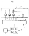
- the plant 1 to be monitored is, for example, a hydroelectric power plant which contains turbines 2 as hydromechanical components. Since it is sufficient for the understanding, only one of the turbines 2 is symbolically indicated in FIG. Of course, usually more than one turbine 2 are provided in the system 1.
- a plurality of sensors 31, 32, 33,..., 3 n are provided for the metrological detection of state variables x 1 , x 2 , x 3 ,..., X n . Not all state variables have to be measured directly at the component 2, but also state variables at other parts of the plant can be measured, such as For example, the pressure of the water in the pressure line.
- state variables x 1 , x 2 , x 3 ,..., X n which are detected metrologically, depends on the type of system or component to be monitored. It is the experience of the skilled person to choose the appropriate state variables for the respective application.
- the sensors 31-3n transmit the data measured by them via signal lines 41, 42, 43,..., 4n, for example feeder optical lines, to an evaluation and storage device 5, where the data, if appropriate after conditioning or further processing, are measured values get saved.
- measured values x 1t , x 2t , x 3t ,..., X nt are respectively measured at predeterminable time intervals, for example every minute or every 10 minutes, by means of the sensors 31-3n for the set X of state variables recorded and stored in the evaluation and storage unit.
- the index t is equivalent to a run index, which indexes the temporally successive measured values.
- a model A for the operating behavior of the component 2 is created and evaluated.
- at least one monitoring variable which is independent of the current operating point, is determined at predefinable time intervals.
- the monitoring size in particular their time course is graphically represented by means of an output unit 6.
- the wear can be assessed and malfunctions can be detected. With wear doing business-related, usually slowly progressive changes are meant, for example in the shaft bearing or in the shaft seal of the turbine 2 and z. B.Dracks in lines or contamination of filters.
- Malfunctions may be, for example, failures or malfunctions of one of the sensors 31-3n or the actuators monitored by them (eg valves, control flaps) or faults in the system 1 or component 2, such as changes in vibrations or overheating of bearings or seals ,
- a warning device 7 for triggering an alarm.
- This warning device is activated if the monitored variable leaves a predefinable normal range.
- the alarm can be done, for example, visually and / or acoustically.
- the model A is a model which is obtained directly from experimental data, that is to say from the measured values x it recorded by the sensors 31-3n for the state variables x i .
- the modeling phase refers to a time-limited period of operation of the component 2 or the system 1, during which the system 1 operates in normal, ie trouble-free operation.
- the choice of modeling phase may be based on experience.
- the modeling phase is chosen to be so long that it comprises several different operating points from the operating range of component 2.
- measured values x it are collected for the state variables x i . These measured values x it therefore refer to several different operating points. Since the time interval of the measured value acquisition, that is to say the time between the measurement t and the measurement t + 1, can be relatively short, it may be advantageous to temporally average a plurality of temporally successive measured values for a state variable x i , or else to combine them with known statistical methods , for example by forming correlation matrices. In order to make this clear, the index T is used instead of the index t to indicate that the corresponding value can also represent the combination of several individual values. So z. For example, the measured values will be denoted by x iT in the future.
- At least one of the state variables x i is selected for which a model value y i is determined by means of the model A.
- As input variables of the model A at least a part of the set X of the state variables x i is used.
- the model A can be configured in a similar manner in such a way that its output variables comprise model values for more than one of the state variables x i .
- the state variable to be modeled in the exemplary embodiment described here is that with the index n, that is to say the output variable of the model is the model value y n for the state variable x n .
- measured values are therefore available for m times or time intervals.
- X * T see FIG.
- the m sets X T of measured values provide m determinative equations for the n model parameters a i . Since, as a rule, the number m of the sets of measured values is greater than the number n of the model parameters a i , the system of the determination equations is overdetermined. However, sufficient mathematical methods are known in order to determine the best possible values for the model parameters a i by means of the determination equations. Examples of suitable methods are the Equalization Calculation Method, the least squares method, the Singular Value Decomposition (SVD) method or the Principal Component Analysis (PCA). Since such methods are well known, they will not be explained in detail here.
- step 101 see FIG.
- a model error ⁇ is determined in step 102, which is a measure of the goodness of the model is.
- the model error ⁇ can be, for example, the normalized sum of the squares of the residuals.
- the model A is optimized until the model error ⁇ is minimal or falls below a predetermined limit. When this is achieved, model A is sufficiently good for monitoring (step 104).
- the creation and optimization of the model A can take place in only one step or in several steps.
- the system of the determination equations for the model parameters a i can be solved so that the resulting values for the model parameters a i already represent an optimized solution.
- model A creation of the model A and its optimization in several successive steps, ie the model A is first created, resulting in initial values for the model parameters, and then the model parameters are optimized in one or more iterative steps until the model error is minimal.
- Such an iterative procedure is usually necessary if the determinative equations for the model parameters do not exist solve analytically, z. For example, if neural networks are used as the model structure.
- Model A takes into account the current operating point.
- each measured value set is evaluated individually or the measured value sets are each over a period of time, for. As a day, collected and then averaged or summarized otherwise. For example, correlations or cross-correlations can also be determined.
- the model value y n is then determined from the measured values for the state variables x 1 , x 2 ,..., X n-1 by means of the model A.
- the monitored variable is transmitted to the output unit 6, where the time course of the monitored variable is preferably graphically, z. B. on a monitor.
- the monitoring size regardless of the current operating point, in time substantially constant. If a malfunction occurs, such as a failure of a sensor or overheating, this means that the model value, which indeed describes the normal operation, deviates more strongly from the actual measured value. Consequently, the monitored variable changes, which is very easily recognizable in its graphical representation. Usually, the occurrence of malfunctions leads to a temporally rapid change in the monitored variable.
- threshold values for the monitoring variable which limit the normal range of the monitored variable. If the threshold values are exceeded, activation of the warning device 7 causes an alarm, z. As an optical and / or acoustic signal, triggered or given a warning. Since the monitored variable is independent of the current operating point, such threshold values for the monitored variable are synonymous with flexible ones respective operating point adapted thresholds for the state variables.
- the threshold value for the monitoring variable can be chosen to be equal to or slightly larger than the largest of the residuals r 1 , r 2 ,... R m of the modeling phase.
- model structure for the model A can be other than the described linear static.
- the model structure may be a nonlinear one in which z. B. enter into products of the state variables. It is also possible a linear dynamic model structure z.
- all state variables x i are used as input variables, the value of this state variable being taken into account in the determination of the model value for the state variable x nT at an earlier point in time, x nT-1 .
- a model structure is used which is linear in the model parameters a i , because then the model parameters a i can normally be determined analytically.
- the index "u” is used in the following to mark the chronological order of the determined or recorded quantities (measured values, model values, models, residuals). So z. B. x iu the measured value, which is detected at a certain, designated by "u" time for the state variable x i and x iu + 1 the measured value of the same state variable x i is detected in the next measurement. As already mentioned above, the measured values, which are recorded, for example, every few minutes, can first be measured over a predefinable time period, eg. As a day, collected and then averaged and / or different, z. B. are summarized by formation of cross-correlations before the further process steps take place.
- x iu denotes the measurement averaged or summarized over this period denoted by u. This means that it is not differentiated in the following whether each recorded measured value set is evaluated individually, or whether a temporal averaging over several sets of measured values takes place. This difference is immaterial to understanding.
- the model A is first of all based on created and optimized the measured values acquired in the modeling phase.
- the following explanations therefore only refer to the operation of Appendix 1 after the modeling phase.
- a set of measured values x 1u , x 2u ,..., X nu for the set of state variables x 1 , x 2 ,..., X n is detected at predeterminable time intervals (step 201).
- the model A is updated at predeterminable time intervals by means of the evaluation and storage device 5, that is, as will be explained further below, in each case a current model M u is determined (step 205).
- a nominal value s nu for the state variable x n is determined for at least one fixed reference working point (step 206), which serves as a monitoring variable and is transmitted to the output unit 6 (step 207).
- the respective current model M u is always evaluated at the same reference operating point, irrespective of which operating point the system 1 or the component 2 is currently operating.
- This fixed reference working point which is defined by fixed values for the state variables x i , is preferably selected such that it lies approximately in the middle of the operating range of the system 1 or the component 2, for example. B. at the best point, or in the vicinity of a working point at which the system 1 or the component 2 often works or is operated.
- the determination and optimization of the respective current model M u can, for example, be carried out in a manner similar to that described above with reference to the generation of the model A from the measured values x iT of the modeling phase is described (see Fig. 1). That is, the update is a new determination of the model based on the set of measurements x 1u , x 2u , ... x nu .
- the model value y nu for the state variable x n is determined with the aid of the last current model M u-1 or with the help of the newly determined model.
- the residual r nu x nu -y nu is formed, which is the difference between the actual measured value x nu and the model value y nu .
- this residual r nu is minimized or, if several residuals are determined, a model error that can be determined from the residuals, eg. For example, the normalized sum of the squares of the residuals is minimized.
- the creation and optimization of the current model M u may be done in one step.
- the associated model parameters of the model M u-1 Before the last current model N is changed u-1 and the model is re-calculated, the associated model parameters of the model M u-1, and a characteristic quantity which is representative of the quality of this model M u-1, for example, correlation matrices and / or estimated variances of measurement noise.
- the older models whose model parameters and model uncertainties or qualities are stored, in particular in a weighted manner, are taken into account.
- a preferred realization of this incorporation of older models is explained below with reference to the flow chart in FIG. 3.
- a model M u * is created and optimized in step 203 ( eg analogous to the front described), which model M u * is based only on those measured values x 1u , x 2u , ..., x nu , which have been recorded since the last update.
- the symbol "*" is thus intended to indicate that only the measured values x 1u , x 2u , ..., x nu , which were determined in the period of time indicated by u, are used to create this model M u *.
- M u-1 * designates the model for the production of which the measurement values x 1 (u-1) , x 2 (u-1) ,..., X n (u ) recorded in the period of time indicated by (u-1) -1) can be used, etc.
- step 204 the model M u * is stored in the evaluation and storage device 5 (FIG. 1) together with parameters which are representative of its quality, for example correlation matrices and / or estimated variances of the measurement noise.
- the current model M u is then determined, which takes into account the older models M u-1 *, M u-2 *,..., For example as the sum of the form :.
- M u M u * + ⁇ M u - 1 * + ⁇ 2 M u - 2 * + ...
- ⁇ denotes a weighting factor or a forgetting factor.
- the weighting or forgetting factor ⁇ can be determined, for example, from the parameters which are stored together with the models M u-1 *, M u-2 *,...
- the current model M u After the current model M u has been determined and optimized, it is evaluated at the reference working point (step 206) and thus the nominal value s nu is determined as the monitoring variable and transmitted to the output unit 6 (FIG. 1).
- the respective current model M takes into account and the older models - that is, the history - because in the determination of the model M u-1 walked the models N U 1 * and M U-2, where u in M -2 models M u-2 * and M u-3 , etc.
- This variant has the advantage of requiring very little storage space, because the entire history (temporal evolution) is always described by a single model.
- the updating for determining the respective current model M u takes place regularly at predefinable time intervals, for example once a day.
- the monitoring quantity is not a difference between measured value and model value, but the nominal value s nu .
- This is the model value that is for the fixed reference working point from the respective current model M u . Consequently, even with this procedure, the monitoring variable s nu is independent of the current operating point. It always refers to the fixed reference working point. In other words, the monitoring quantity s nu indicates what value the state variable x n would have if the system 1 or the component 2 were operating at the reference operating point. It is obvious that the monitoring quantity s nu is substantially constant over time, as long as the plant 1 or the component 2 operates in normal operation.
- the model is updated regardless of whether a malfunction has occurred or not. If a change (fault, sensor failure, wear) occurs in the system 1 or component 2 to be monitored, this change will be incorporated into the current model M u during the update. Consequently, the current model M u then no longer represents the normal operation, but the changed by disturbance and / or wear operation. If the current model is now evaluated at the reference working point, the result is a nominal value s nu , which deviates from that of normal operation. Thus, in the graphical representation of the monitored variable as a function of time shows a deviation from the constant behavior. Again, malfunctions usually result in a temporally relatively rapid change in the monitored variable, while slowly progressive changes, such as those caused by wear, cause a comparatively slower and continuous change in the time course of the monitored variable s nu .
- a particular advantage of this kind of monitoring lies in the fact that it is also possible to identify or determine trends for the further operation of the components 2 or the system 1. This will be explained using the example of the wear of a seal. If the seal wears continuously, for example, this leads to a continuous increase in the time course of the monitored variable. Since the monitoring quantity always refers to the same reference operating point, it is thus possible to predict how long the seal will still be functional. As a result, maintenance work can be planned much better and more efficiently, and it is much less likely to cause unexpected and uneconomic business failures. For this reason too, the maintenance and operating costs of systems for industrial applications can be considerably reduced by the method according to the invention.
- an error isolation is also carried out, that is to say the error which has occurred is localized as well as possible.
- the aim of this fault isolation is to locate as precisely as possible that state variable or sensor 31-3n, which is responsible for ensuring that the deviation from normal operating behavior has occurred. If, for example, a storage temperature serves as the monitoring variable, then an abnormality z. B. on the one hand by a malfunction of the associated Sensors are caused on the other hand, but also by a malfunction in another area of the component or the system, eg. For example, by an inadmissible increase in the flow rate or by a malfunction of the sensor that detects the flow rate.
- the fault isolation is preferably carried out as follows:
- n 4 state variables x 1 , x 2 , x 3 , x 4 are detected metrologically and, as described above, the model A for the operating behavior or the current model M u is determined.
- the model dimension which corresponds to the dimension of the hypersurface spanned by the n-dimensional performance model of the n state variables, is three in this example.
- Such a sub-model is characterized by the fact that its model dimension is at least one lower than the model dimension of the model A or the current model M u .
- two-dimensional partial models are used, ie the model dimension of the partial models is two.
- the following submodels can be determined: m1 (x 1, x 2, x 3); m2 (x 1, x 2, x 4); m3 (x 1, x 3, x 4); m4 (x 2 , x 3 , x 4 )
- b 0 , b 1 and b 2 designate model parameters.
- the state variable x 4 is no longer included in the submodel m1.
- the state variable x 3 no longer enters the submodel m2
- the state variable x 2 no longer enters into the submodel m3
- the State variable x 1 is no longer included in submodel m4.
- the submodels m1-m4 which of the state variables x i serve as input variables and which as output variables.
- the partial model m1 it is possible to calculate the state variable x 1 from the state variables x 2 and x 3 , or to calculate the state variable x 2 from the state variables x 1 and x 3 , or the state variable x 3 from the state variables x 1 and x 2 to calculate.
- the partial models m2, m3 and m4 it is possible to calculate the state variable x 1 from the state variables x 2 and x 3 , or to calculate the state variable x 2 from the state variables x 1 and x 3 from the state variables x 1 and x 2 to calculate.
- the partial models m2, m3 and m4 it is possible to calculate the state variable x 1 from the state variables x 2 and x 3 , or to calculate the state variable x 2 from the state variables x 1 and x 2 to calculate.
- values are now determined for the state variables x 1 , x 2 , x 3 , x 4 , which are referred to as reconstructed values.
- a reconstruction error is determined for each of the submodels m 1-m 4, which is representative of how well the reconstructed values determined by the associated submodel match match the measured values. If the reconstruction error is greater than a predefinable threshold value, the associated submodel is assessed as faulty, otherwise it is not faulty.
- the thresholds for the reconstruction errors can be, for example, based on the residuals, the z. As determined in the modeling phase set.
- the submodels are divided into two classes: erroneous and non-defective. Based on the combinations of state variables x i that lead to defective submodels, and the combinations of state variables x i that are not faulty Submodels lead, then can isolate the faulty state variable.
- a fault liability of the state variable x 2 or of the sensor 32 leads to the fact that only the partial model, into which x 2 does not enter, namely m 3 , is judged not to be faulty.
- An error of the state variable x 3 or the sensor 33 leads to the fact that only the submodel m2 is judged not to be faulty, and a fault liability of the state variable x 4 or the sensor 34 leads to the fact that only the submodel m1 is not faulty.
- the error can be localized on the basis of the partial models m1-m4, more precisely, the faulty state variable or the faulty sensor can be isolated.
- n state variables x i 1, 2,..., N.
- the maximum model dimension of the Model for the operating behavior n-1 that is, the model for the operating behavior determines an n-1-dimensional hypersurface in the n-dimensional space of the n state variables.
- the partial models required for fault isolation each have a model dimension d that is smaller than the model dimension n-1 of the model for the operating behavior, that is d ⁇ n-1.
- each sub-model represents a d-dimensional hypersurface into a (d + 1) -dimensional space. Since the n state variables x i are generally highly correlated, ie not independent of one another, the model A or M u is analytically redundant for the operating behavior. Due to this analytical redundancy, the errors can be isolated by the submodels.
- the number of faulty state variables or faulty sensors that can be isolated by means of the submodels equals the difference between the model dimension of the model for the operating behavior and the model dimension of the individual submodels. For practical purposes, it is often sufficient if this difference is one.
- model structures other than the linear model structure mentioned here by way of example for the submodels.
- the above explanations regarding the model structure of the model for the operating behavior apply mutatis mutandis to the submodels.
- the creation of the individual submodels can, for example, be done in the same way as the creation of the model for the operating behavior, ie directly from the measured values for the state variables. Alternatively, however, the following procedure is possible.
- the individual submodels are determined, that is, the overall model is projected onto a space of a lower dimension in each case.
- the mathematical methods required for projection are known per se and will not be explained in detail here.
- a suitable model dimension d for the submodels or for the overall model can be done, for example, by means of the SVD method.
- the determination, storage and evaluation of the partial models preferably takes place in the evaluation and storage device 5.
Priority Applications (7)
| Application Number | Priority Date | Filing Date | Title |
|---|---|---|---|
| DE59712546T DE59712546D1 (de) | 1997-07-31 | 1997-07-31 | Verfahren zum Überwachen von Anlagen mit mechanischen Komponenten |
| AT97810550T ATE315815T1 (de) | 1997-07-31 | 1997-07-31 | Verfahren zum überwachen von anlagen mit mechanischen komponenten |
| EP97810550A EP0895197B1 (de) | 1997-07-31 | 1997-07-31 | Verfahren zum Überwachen von Anlagen mit mechanischen Komponenten |
| US09/006,925 US6208953B1 (en) | 1997-07-31 | 1998-01-14 | Method for monitoring plants with mechanical components |
| EG89398A EG22325A (en) | 1997-07-31 | 1998-07-29 | Method for monitoring plants with mechanical components |
| DZ980185A DZ2575A1 (fr) | 1997-07-31 | 1998-07-29 | Procédé pour surveiller des installations avec descomposants mécaniques. |
| NO19983514A NO322764B1 (no) | 1997-07-31 | 1998-07-30 | Fremgangsmate for overvakning av anlegg med mekaniske komponenter |
Applications Claiming Priority (1)
| Application Number | Priority Date | Filing Date | Title |
|---|---|---|---|
| EP97810550A EP0895197B1 (de) | 1997-07-31 | 1997-07-31 | Verfahren zum Überwachen von Anlagen mit mechanischen Komponenten |
Publications (2)
| Publication Number | Publication Date |
|---|---|
| EP0895197A1 EP0895197A1 (de) | 1999-02-03 |
| EP0895197B1 true EP0895197B1 (de) | 2006-01-11 |
Family
ID=8230334
Family Applications (1)
| Application Number | Title | Priority Date | Filing Date |
|---|---|---|---|
| EP97810550A Expired - Lifetime EP0895197B1 (de) | 1997-07-31 | 1997-07-31 | Verfahren zum Überwachen von Anlagen mit mechanischen Komponenten |
Country Status (7)
| Country | Link |
|---|---|
| US (1) | US6208953B1 (un) |
| EP (1) | EP0895197B1 (un) |
| AT (1) | ATE315815T1 (un) |
| DE (1) | DE59712546D1 (un) |
| DZ (1) | DZ2575A1 (un) |
| EG (1) | EG22325A (un) |
| NO (1) | NO322764B1 (un) |
Cited By (1)
| Publication number | Priority date | Publication date | Assignee | Title |
|---|---|---|---|---|
| WO2012055699A1 (de) | 2010-10-28 | 2012-05-03 | Eads Deutschland Gmbh | Instandhaltungsinformationsvorrichtung, zustandssensor zur verwendung darin sowie damit durchführbares verfahren zur entscheidungsfindung für oder gegen eine instandhaltung |
Families Citing this family (53)
| Publication number | Priority date | Publication date | Assignee | Title |
|---|---|---|---|---|
| GB9822992D0 (en) | 1998-10-22 | 1998-12-16 | British Aerospace | Fatigue monitoring systems and methods |
| US6944583B1 (en) * | 2000-02-02 | 2005-09-13 | Centric Software, Inc. | Multi-threaded frame safe synchronization of a simulation |
| US6539343B2 (en) * | 2000-02-03 | 2003-03-25 | Xerox Corporation | Methods for condition monitoring and system-level diagnosis of electro-mechanical systems with multiple actuating components operating in multiple regimes |
| FI20000454A0 (fi) * | 2000-02-28 | 2000-02-28 | Neles Paper Automation Oy | Valvontajärjestelmä ja sen käyttö |
| DE60105421T2 (de) * | 2000-04-05 | 2005-09-22 | Liqum Oy | Verfahren und system zum überwachen und analysieren eines papierherstellungsprozesses |
| WO2002015131A1 (de) * | 2000-08-17 | 2002-02-21 | Siemens Aktiengesellschaft | Diagnoseverfahren zum erkennen von alterungserscheinungen einer dampfturbine |
| JP3855651B2 (ja) * | 2000-08-29 | 2006-12-13 | 日本精工株式会社 | 転がり軸受の寿命予測方法、寿命予測装置、寿命予測装置を使用した転がり軸受選定装置及び記憶媒体 |
| EP1189126B1 (de) * | 2000-09-14 | 2006-06-28 | Sulzer Markets and Technology AG | Verfahren zum Überwachen einer Anlage |
| US6587737B2 (en) | 2000-09-14 | 2003-07-01 | Sulzer Makert And Technology Ag | Method for the monitoring of a plant |
| FI20002296A (fi) * | 2000-10-17 | 2002-04-18 | Lumeo Software Oy | Mekaanisen alisysteemin ja hydraulisen alisysteemin omaavan systeemin simulointi |
| US6477485B1 (en) * | 2000-10-27 | 2002-11-05 | Otis Elevator Company | Monitoring system behavior using empirical distributions and cumulative distribution norms |
| US7299162B2 (en) * | 2000-12-14 | 2007-11-20 | Siemens Corporate Research, Inc. | Method and apparatus for providing a polynomial based virtual age estimation for remaining lifetime prediction of a system |
| US6795798B2 (en) * | 2001-03-01 | 2004-09-21 | Fisher-Rosemount Systems, Inc. | Remote analysis of process control plant data |
| JP4138267B2 (ja) * | 2001-03-23 | 2008-08-27 | 株式会社東芝 | 半導体製造装置、真空ポンプの寿命予測方法及び真空ポンプの修理タイミング決定方法 |
| US6532433B2 (en) | 2001-04-17 | 2003-03-11 | General Electric Company | Method and apparatus for continuous prediction, monitoring and control of compressor health via detection of precursors to rotating stall and surge |
| GB0109643D0 (en) * | 2001-04-19 | 2001-06-13 | Isis Innovation | System and method for monitoring and control |
| DE10121728A1 (de) | 2001-05-04 | 2002-11-07 | Infineon Technologies Ag | Verfahren zur hybrid-automatisierten Überwachung von Produktionsmaschinen |
| CA2450177C (en) * | 2001-06-08 | 2012-09-11 | Netuitive, Inc. | Automated analyzers for estimation systems |
| US20030046382A1 (en) * | 2001-08-21 | 2003-03-06 | Sascha Nick | System and method for scalable multi-level remote diagnosis and predictive maintenance |
| JP4184638B2 (ja) * | 2001-08-31 | 2008-11-19 | 株式会社東芝 | 半導体製造装置の寿命診断方法 |
| JP2003077907A (ja) * | 2001-08-31 | 2003-03-14 | Toshiba Corp | 生産装置の異常停止回避方法及び異常停止回避システム |
| JP4149691B2 (ja) * | 2001-08-31 | 2008-09-10 | 株式会社東芝 | 半導体製造装置用回転機の寿命予測方法及び半導体製造装置 |
| US20030069743A1 (en) * | 2001-09-21 | 2003-04-10 | Nordrum Susann B. | System and method for energy and green-house gas inventory management |
| US7280988B2 (en) * | 2001-12-19 | 2007-10-09 | Netuitive, Inc. | Method and system for analyzing and predicting the performance of computer network using time series measurements |
| FI114170B (fi) * | 2002-03-14 | 2004-08-31 | Metso Automation Oy | Kunnonvalvontajärjestelmä koneenohjausjärjestelmällä varustettuja pyöriviä kone-elimiä sisältäviä koneita varten |
| US7097351B2 (en) * | 2002-09-30 | 2006-08-29 | Flowserve Management Company | System of monitoring operating conditions of rotating equipment |
| WO2005045678A2 (en) | 2003-10-27 | 2005-05-19 | Netuitive, Inc. | Computer performance estimation system configured to take expected events into consideration |
| US20050096759A1 (en) * | 2003-10-31 | 2005-05-05 | General Electric Company | Distributed power generation plant automated event assessment and mitigation plan determination process |
| DE50306976D1 (de) | 2003-11-19 | 2007-05-16 | Siemens Ag | Verfahren zur Überwachung einer technischen Einrichtung |
| US7062370B2 (en) * | 2004-03-30 | 2006-06-13 | Honeywell International Inc. | Model-based detection, diagnosis of turbine engine faults |
| US7369965B2 (en) * | 2004-06-28 | 2008-05-06 | Honeywell International, Inc. | System and method for turbine engine anomaly detection |
| WO2006007621A2 (de) * | 2004-07-22 | 2006-01-26 | Avl List Gmbh | Verfahren zur untersuchung des verhaltens von komplexen systemen, insbesondere von brennkraftmaschinen |
| US7457674B2 (en) * | 2004-08-27 | 2008-11-25 | Siemens Corporate Research, Inc. | System, device, and methods for updating system-monitoring models |
| CN101048714B (zh) * | 2004-08-27 | 2010-05-12 | 西门子共同研究公司 | 用于更新系统监控模型的系统、设备以及方法 |
| WO2006107295A1 (en) * | 2005-04-01 | 2006-10-12 | Honeywell International Inc. | Model-based detection, diagnosis of turbine engine faults |
| US7536371B2 (en) * | 2005-12-05 | 2009-05-19 | Insyst Ltd. | Apparatus and method for the analysis of a process having parameter-based faults |
| DE102007019201B4 (de) | 2007-04-20 | 2009-06-04 | Phoenix Contact Gmbh & Co. Kg | Abgleichen von Daten eines Steuer- und/oder Datenübertragungssystems und eines dieses repräsentierenden Systemmodells |
| DE102007028891A1 (de) * | 2007-06-20 | 2009-01-15 | Evonik Energy Services Gmbh | Verfahren zum Überwachen der Beanspruchung eines Rohrleitungsabschnitts |
| DE102008016025A1 (de) * | 2008-03-28 | 2009-10-01 | Mtu Aero Engines Gmbh | Verfahren und Messsystem zum Charakterisieren einer Abweichung eines Istmaßes eines Bauteils von einem Nennmaß des Bauteils |
| US8306778B2 (en) * | 2008-12-23 | 2012-11-06 | Embraer S.A. | Prognostics and health monitoring for electro-mechanical systems and components |
| US8955365B2 (en) * | 2008-12-23 | 2015-02-17 | Embraer S.A. | Performance monitoring and prognostics for aircraft pneumatic control valves |
| EP2287685B1 (en) * | 2009-07-23 | 2015-07-15 | Siemens Aktiengesellschaft | Method for monitoring operation behaviour of a component of an industrial plant |
| DE102011081346A1 (de) * | 2011-08-22 | 2013-02-28 | Robert Bosch Gmbh | Verfahren zum Erstellen einer Funktion für ein Steuergerät |
| US9529348B2 (en) | 2012-01-24 | 2016-12-27 | Emerson Process Management Power & Water Solutions, Inc. | Method and apparatus for deploying industrial plant simulators using cloud computing technologies |
| US9957843B2 (en) | 2013-12-31 | 2018-05-01 | General Electric Company | Methods and systems for enhancing control of power plant generating units |
| US20150184549A1 (en) | 2013-12-31 | 2015-07-02 | General Electric Company | Methods and systems for enhancing control of power plant generating units |
| DE102017219543A1 (de) * | 2017-11-03 | 2019-05-09 | Robert Bosch Gmbh | Verfahren und Anordnung zum Überwachen eines Betriebs einer Anlage |
| DE102017131087A1 (de) * | 2017-12-22 | 2019-06-27 | Endress + Hauser Process Solutions Ag | Verfahren zum Überwachen einer Messstelle in einer Anlage der Prozessautomatisierung |
| WO2019222152A1 (en) * | 2018-05-18 | 2019-11-21 | Siemens Aktiengesellschaft | Online fault localization in industrial processes without utilizing a dynamic system model |
| JP7267109B2 (ja) * | 2019-05-31 | 2023-05-01 | 三菱重工業株式会社 | 蒸気タービンのシールクリアランス調整方法 |
| DE102021116562A1 (de) | 2021-06-25 | 2022-12-29 | Schenck Process Europe Gmbh | Überwachung des betriebs einer maschine |
| DE102021003960A1 (de) | 2021-07-28 | 2023-02-02 | Stöber Antriebstechnik GmbH & Co. KG | Verfahren zum Erkennen von drohenden Ausfällen von Komponenten von Maschinen, insbesondere von Antriebseinheiten |
| DE102021208443A1 (de) | 2021-08-04 | 2023-02-09 | BSH Hausgeräte GmbH | Erkennung einer Anomalie an einem Haushaltsgerät |
Family Cites Families (16)
| Publication number | Priority date | Publication date | Assignee | Title |
|---|---|---|---|---|
| US4184205A (en) * | 1977-11-25 | 1980-01-15 | Ird Mechanalysis, Inc. | Data acquisition system |
| DD146359B3 (de) * | 1979-09-26 | 1992-07-30 | Veag Vereinigte Energiewerke Ag | Verfahren zur bauteilueberwachung und prozesssteuerung in dampferzeugeranlagen |
| DE3133222A1 (de) * | 1981-08-21 | 1983-03-03 | Kraftwerk Union AG, 4330 Mülheim | Verfahren zur ermittlung des augenblicklichen und des zukuenftigen zustandes eines technischen prozesses mit hilfe von nichtlinearen prozessmodellen |
| FR2539874B1 (fr) * | 1983-01-20 | 1985-07-05 | Alsthom Atlantique | Systeme de surveillance de l'endommagement en torsion d'une ligne d'arbres composee d'une machine entrainante et d'une machine entrainee |
| US4719587A (en) * | 1985-04-16 | 1988-01-12 | Combustion Engineering, Inc. | Future behavior equipment predictive system |
| SE463338B (sv) * | 1989-06-14 | 1990-11-05 | Ludwik Liszka | Saett att oevervaka och/eller diagnosticera aktuella drifttillstaand hos komplicerade maskiner |
| US5210704A (en) * | 1990-10-02 | 1993-05-11 | Technology International Incorporated | System for prognosis and diagnostics of failure and wearout monitoring and for prediction of life expectancy of helicopter gearboxes and other rotating equipment |
| EP0496570B1 (en) * | 1991-01-22 | 1998-06-03 | Honeywell Inc. | Two-level system identifier apparatus with optimization |
| FR2676556B1 (fr) * | 1991-05-15 | 1993-07-23 | Europ Gas Turbines Sa | Systeme de surveillance predictive d'un processus. |
| FR2677152B1 (fr) * | 1991-05-28 | 1993-08-06 | Europ Gas Turbines Sa | Procede et dispositif de surveillance d'un appareil fonctionnant dans des conditions variables. |
| US5633800A (en) * | 1992-10-21 | 1997-05-27 | General Electric Company | Integrated model-based reasoning/expert system diagnosis for rotating machinery |
| DE4243882C1 (de) * | 1992-12-23 | 1994-01-05 | Baleanu Michael Alin | Verfahren und Einrichtung zur Überwachung eines technischen Prozesses |
| US5465321A (en) * | 1993-04-07 | 1995-11-07 | The United States Of America As Represented By The Administrator Of The National Aeronautics And Space Administration | Hidden markov models for fault detection in dynamic systems |
| JP3169036B2 (ja) * | 1993-06-04 | 2001-05-21 | 株式会社日立製作所 | プラント監視診断システム、プラント監視診断方法および非破壊検査診断方法 |
| JPH07132440A (ja) * | 1993-11-02 | 1995-05-23 | Fanuc Ltd | 加工負荷監視方式 |
| US5796920A (en) * | 1994-08-19 | 1998-08-18 | Harris Corporation | Multiprocessor system and method for identification and adaptive control of dynamic systems |
-
1997
- 1997-07-31 EP EP97810550A patent/EP0895197B1/de not_active Expired - Lifetime
- 1997-07-31 DE DE59712546T patent/DE59712546D1/de not_active Expired - Lifetime
- 1997-07-31 AT AT97810550T patent/ATE315815T1/de not_active IP Right Cessation
-
1998
- 1998-01-14 US US09/006,925 patent/US6208953B1/en not_active Expired - Fee Related
- 1998-07-29 EG EG89398A patent/EG22325A/xx active
- 1998-07-29 DZ DZ980185A patent/DZ2575A1/xx active
- 1998-07-30 NO NO19983514A patent/NO322764B1/no not_active IP Right Cessation
Cited By (3)
| Publication number | Priority date | Publication date | Assignee | Title |
|---|---|---|---|---|
| WO2012055699A1 (de) | 2010-10-28 | 2012-05-03 | Eads Deutschland Gmbh | Instandhaltungsinformationsvorrichtung, zustandssensor zur verwendung darin sowie damit durchführbares verfahren zur entscheidungsfindung für oder gegen eine instandhaltung |
| DE102010049909A1 (de) | 2010-10-28 | 2012-05-03 | Eads Deutschland Gmbh | Instandhaltungsinformationsvorrichtung, Zustandssensor zur Verwendung darin sowie damit durchführbares Verfahren zur Entscheidungsfindung für oder gegen eine Instandhaltung |
| US9477222B2 (en) | 2010-10-28 | 2016-10-25 | Eads Deutschland Gmbh | Maintenance information device, condition sensor for use therein and method which can be carried out therewith for arriving at a decision whether or not to perform servicing or maintenance |
Also Published As
| Publication number | Publication date |
|---|---|
| EG22325A (en) | 2002-12-31 |
| DZ2575A1 (fr) | 2003-02-22 |
| EP0895197A1 (de) | 1999-02-03 |
| NO322764B1 (no) | 2006-12-04 |
| DE59712546D1 (de) | 2006-04-06 |
| US6208953B1 (en) | 2001-03-27 |
| ATE315815T1 (de) | 2006-02-15 |
| NO983514L (no) | 1999-02-01 |
| NO983514D0 (no) | 1998-07-30 |
Similar Documents
| Publication | Publication Date | Title |
|---|---|---|
| EP0895197B1 (de) | Verfahren zum Überwachen von Anlagen mit mechanischen Komponenten | |
| EP1543394B1 (de) | Vorrichtung und verfahren zur überwachung einer mehrere systeme umfassenden technischen anlage, insbesondere einer kraftwerksanlage | |
| DE69910800T2 (de) | Verfahren und Vorrichtung zur Überwachung des Betriebszustandes einer einzelnen Maschine | |
| DE3421522A1 (de) | Verfahren und einrichtung zur diagnose eines waermekraftwerks | |
| DE2622120A1 (de) | Verfahren und vorrichtung zur automatischen ueberwachung von anlagen | |
| EP2706422B1 (de) | Verfahren zur rechnergestützten Überwachung des Betriebs eines technischen Systems, insbesondere einer elektrischen Energieerzeugungsanlage | |
| EP1892597A1 (de) | Zustandsüberwachung von Maschinen und technischen Anlagen | |
| DE112018001684T5 (de) | Indikatorerfassungssystem und Indikatorerfassungsverfahren | |
| EP3282399B1 (de) | Verfahren zur verbesserten erkennung von prozessanomalien einer technischen anlage sowie entsprechendes diagnosesystem | |
| EP3876060B1 (de) | Verfahren und recheneinheit zur ursachenanalyse eines anomalen zustandes einer maschine | |
| WO2020216530A1 (de) | Verfahren zum bestimmen von restnutzungszyklen, restnutzungszyklusbestimmungsschaltung, restnutzungszyklusbestimmungsvorrichtung | |
| DE102008037532A1 (de) | Automatische Detektion und Meldung von Verschleiss innerer Turbinenkomponenten | |
| DE102020202865B3 (de) | Verfahren und Recheneinheit zur Überwachung des Zustandes einer Maschine | |
| EP1189126B1 (de) | Verfahren zum Überwachen einer Anlage | |
| DE69728942T2 (de) | System zur Auswertung des Zustandes einer Vakuumpumpe | |
| DE102019101910B4 (de) | Wärmeversatzkorrekturvorrichtung | |
| DE102020200051A1 (de) | Verfahren zum Bestimmen von Restnutzungszyklen, Restnutzungszyklusbestimmungsschaltung, Restnutzungszyklusbestimmungsvorrichtung | |
| DE102017205712B4 (de) | Computerimplementiertes Verfahren zum Betreiben eines Wellenerdungssystems, Wellenerdungssystem einer Drehapparatur | |
| EP2388602B1 (de) | Verfahren zur Diagnose von Kontakten einer Photovoltaikanlage und Vorrichtung | |
| EP2206024B1 (de) | Verfahren zur überwachung der güte eines regelkreises in einem kraftwerk | |
| EP1055162A1 (de) | Prozess- und anlagendiagnoseverfahren | |
| EP3819727B1 (de) | Leitsystem für eine technische anlage mit trendkurvendiagramm | |
| EP4226494A1 (de) | Verfahren zur überwachung eines oder mehrerer elektrischer antriebe einer elektromechanischen anlage | |
| EP3959571A1 (de) | Verfahren zum bestimmen von restnutzungszyklen, restnutzungszyklusbestimmungsschaltung, restnutzungszyklusbestimmungsvorrichtung | |
| EP4127848A1 (de) | Verfahren und system zur diagnose von meldungen |
Legal Events
| Date | Code | Title | Description |
|---|---|---|---|
| PUAI | Public reference made under article 153(3) epc to a published international application that has entered the european phase |
Free format text: ORIGINAL CODE: 0009012 |
|
| AK | Designated contracting states |
Kind code of ref document: A1 Designated state(s): AT CH DE FR GB IT LI NL |
|
| AX | Request for extension of the european patent |
Free format text: AL;LT;LV;RO;SI |
|
| 17P | Request for examination filed |
Effective date: 19990706 |
|
| AKX | Designation fees paid |
Free format text: AT CH DE FR GB IT LI NL |
|
| 17Q | First examination report despatched |
Effective date: 20021112 |
|
| RAP1 | Party data changed (applicant data changed or rights of an application transferred) |
Owner name: SULZER MARKETS AND TECHNOLOGY AG |
|
| GRAP | Despatch of communication of intention to grant a patent |
Free format text: ORIGINAL CODE: EPIDOSNIGR1 |
|
| GRAS | Grant fee paid |
Free format text: ORIGINAL CODE: EPIDOSNIGR3 |
|
| GRAA | (expected) grant |
Free format text: ORIGINAL CODE: 0009210 |
|
| AK | Designated contracting states |
Kind code of ref document: B1 Designated state(s): AT CH DE FR GB IT LI NL |
|
| REG | Reference to a national code |
Ref country code: CH Ref legal event code: NV Representative=s name: SULZER MANAGEMENT AG PATENTABTEILUNG/0067 Ref country code: CH Ref legal event code: EP |
|
| GBT | Gb: translation of ep patent filed (gb section 77(6)(a)/1977) |
Effective date: 20060111 |
|
| REF | Corresponds to: |
Ref document number: 59712546 Country of ref document: DE Date of ref document: 20060406 Kind code of ref document: P |
|
| ET | Fr: translation filed | ||
| PLBE | No opposition filed within time limit |
Free format text: ORIGINAL CODE: 0009261 |
|
| STAA | Information on the status of an ep patent application or granted ep patent |
Free format text: STATUS: NO OPPOSITION FILED WITHIN TIME LIMIT |
|
| 26N | No opposition filed |
Effective date: 20061012 |
|
| PGFP | Annual fee paid to national office [announced via postgrant information from national office to epo] |
Ref country code: NL Payment date: 20100714 Year of fee payment: 14 Ref country code: CH Payment date: 20100726 Year of fee payment: 14 |
|
| PGFP | Annual fee paid to national office [announced via postgrant information from national office to epo] |
Ref country code: IT Payment date: 20100726 Year of fee payment: 14 Ref country code: FR Payment date: 20100805 Year of fee payment: 14 Ref country code: DE Payment date: 20100723 Year of fee payment: 14 Ref country code: AT Payment date: 20100714 Year of fee payment: 14 |
|
| PGFP | Annual fee paid to national office [announced via postgrant information from national office to epo] |
Ref country code: GB Payment date: 20100722 Year of fee payment: 14 |
|
| REG | Reference to a national code |
Ref country code: NL Ref legal event code: V1 Effective date: 20120201 |
|
| REG | Reference to a national code |
Ref country code: CH Ref legal event code: PL |
|
| GBPC | Gb: european patent ceased through non-payment of renewal fee |
Effective date: 20110731 |
|
| REG | Reference to a national code |
Ref country code: AT Ref legal event code: MM01 Ref document number: 315815 Country of ref document: AT Kind code of ref document: T Effective date: 20110731 |
|
| REG | Reference to a national code |
Ref country code: FR Ref legal event code: ST Effective date: 20120330 |
|
| PG25 | Lapsed in a contracting state [announced via postgrant information from national office to epo] |
Ref country code: CH Free format text: LAPSE BECAUSE OF NON-PAYMENT OF DUE FEES Effective date: 20110731 Ref country code: FR Free format text: LAPSE BECAUSE OF NON-PAYMENT OF DUE FEES Effective date: 20110801 Ref country code: LI Free format text: LAPSE BECAUSE OF NON-PAYMENT OF DUE FEES Effective date: 20110731 Ref country code: DE Free format text: LAPSE BECAUSE OF NON-PAYMENT OF DUE FEES Effective date: 20120201 |
|
| REG | Reference to a national code |
Ref country code: DE Ref legal event code: R119 Ref document number: 59712546 Country of ref document: DE Effective date: 20120201 |
|
| PG25 | Lapsed in a contracting state [announced via postgrant information from national office to epo] |
Ref country code: IT Free format text: LAPSE BECAUSE OF NON-PAYMENT OF DUE FEES Effective date: 20110731 Ref country code: NL Free format text: LAPSE BECAUSE OF NON-PAYMENT OF DUE FEES Effective date: 20120201 |
|
| PG25 | Lapsed in a contracting state [announced via postgrant information from national office to epo] |
Ref country code: GB Free format text: LAPSE BECAUSE OF NON-PAYMENT OF DUE FEES Effective date: 20110731 |
|
| PG25 | Lapsed in a contracting state [announced via postgrant information from national office to epo] |
Ref country code: AT Free format text: LAPSE BECAUSE OF NON-PAYMENT OF DUE FEES Effective date: 20110731 |