EP0895076B1 - Erfassung des verbrannten Massenbruchteils und Schätzung des Druckes durch den Ionenstrom der Zündkerze - Google Patents
Erfassung des verbrannten Massenbruchteils und Schätzung des Druckes durch den Ionenstrom der Zündkerze Download PDFInfo
- Publication number
- EP0895076B1 EP0895076B1 EP98304395A EP98304395A EP0895076B1 EP 0895076 B1 EP0895076 B1 EP 0895076B1 EP 98304395 A EP98304395 A EP 98304395A EP 98304395 A EP98304395 A EP 98304395A EP 0895076 B1 EP0895076 B1 EP 0895076B1
- Authority
- EP
- European Patent Office
- Prior art keywords
- point
- determining
- mass fraction
- cylinder
- ion signal
- Prior art date
- Legal status (The legal status is an assumption and is not a legal conclusion. Google has not performed a legal analysis and makes no representation as to the accuracy of the status listed.)
- Expired - Lifetime
Links
- 238000002485 combustion reaction Methods 0.000 claims description 80
- 238000000034 method Methods 0.000 claims description 18
- 230000001133 acceleration Effects 0.000 claims description 17
- 238000005259 measurement Methods 0.000 claims description 13
- 239000000446 fuel Substances 0.000 claims description 11
- 239000000203 mixture Substances 0.000 claims description 9
- 230000033001 locomotion Effects 0.000 claims description 8
- 230000015556 catabolic process Effects 0.000 claims description 4
- 150000002500 ions Chemical group 0.000 description 85
- 230000015572 biosynthetic process Effects 0.000 description 12
- 230000006798 recombination Effects 0.000 description 10
- 238000005215 recombination Methods 0.000 description 10
- 230000006835 compression Effects 0.000 description 7
- 238000007906 compression Methods 0.000 description 7
- 238000011161 development Methods 0.000 description 5
- 238000000451 chemical ionisation Methods 0.000 description 3
- 238000012360 testing method Methods 0.000 description 3
- OKTJSMMVPCPJKN-UHFFFAOYSA-N Carbon Chemical compound [C] OKTJSMMVPCPJKN-UHFFFAOYSA-N 0.000 description 2
- 238000013459 approach Methods 0.000 description 2
- 229910052799 carbon Inorganic materials 0.000 description 2
- 239000007795 chemical reaction product Substances 0.000 description 2
- 239000002245 particle Substances 0.000 description 2
- RYGMFSIKBFXOCR-UHFFFAOYSA-N Copper Chemical group [Cu] RYGMFSIKBFXOCR-UHFFFAOYSA-N 0.000 description 1
- 238000009825 accumulation Methods 0.000 description 1
- 239000000969 carrier Substances 0.000 description 1
- 239000007806 chemical reaction intermediate Substances 0.000 description 1
- 239000000567 combustion gas Substances 0.000 description 1
- 230000001186 cumulative effect Effects 0.000 description 1
- 230000007423 decrease Effects 0.000 description 1
- 230000001419 dependent effect Effects 0.000 description 1
- 238000011156 evaluation Methods 0.000 description 1
- 230000005284 excitation Effects 0.000 description 1
- 239000007789 gas Substances 0.000 description 1
- 239000012535 impurity Substances 0.000 description 1
- 230000000977 initiatory effect Effects 0.000 description 1
- 230000007246 mechanism Effects 0.000 description 1
- 238000006386 neutralization reaction Methods 0.000 description 1
- 239000000126 substance Substances 0.000 description 1
Images


Classifications
-
- G—PHYSICS
- G01—MEASURING; TESTING
- G01M—TESTING STATIC OR DYNAMIC BALANCE OF MACHINES OR STRUCTURES; TESTING OF STRUCTURES OR APPARATUS, NOT OTHERWISE PROVIDED FOR
- G01M15/00—Testing of engines
- G01M15/04—Testing internal-combustion engines
- G01M15/042—Testing internal-combustion engines by monitoring a single specific parameter not covered by groups G01M15/06 - G01M15/12
-
- F—MECHANICAL ENGINEERING; LIGHTING; HEATING; WEAPONS; BLASTING
- F02—COMBUSTION ENGINES; HOT-GAS OR COMBUSTION-PRODUCT ENGINE PLANTS
- F02D—CONTROLLING COMBUSTION ENGINES
- F02D35/00—Controlling engines, dependent on conditions exterior or interior to engines, not otherwise provided for
- F02D35/02—Controlling engines, dependent on conditions exterior or interior to engines, not otherwise provided for on interior conditions
- F02D35/021—Controlling engines, dependent on conditions exterior or interior to engines, not otherwise provided for on interior conditions using an ionic current sensor
-
- F—MECHANICAL ENGINEERING; LIGHTING; HEATING; WEAPONS; BLASTING
- F02—COMBUSTION ENGINES; HOT-GAS OR COMBUSTION-PRODUCT ENGINE PLANTS
- F02D—CONTROLLING COMBUSTION ENGINES
- F02D35/00—Controlling engines, dependent on conditions exterior or interior to engines, not otherwise provided for
- F02D35/02—Controlling engines, dependent on conditions exterior or interior to engines, not otherwise provided for on interior conditions
- F02D35/023—Controlling engines, dependent on conditions exterior or interior to engines, not otherwise provided for on interior conditions by determining the cylinder pressure
- F02D35/024—Controlling engines, dependent on conditions exterior or interior to engines, not otherwise provided for on interior conditions by determining the cylinder pressure using an estimation
-
- G—PHYSICS
- G01—MEASURING; TESTING
- G01L—MEASURING FORCE, STRESS, TORQUE, WORK, MECHANICAL POWER, MECHANICAL EFFICIENCY, OR FLUID PRESSURE
- G01L23/00—Devices or apparatus for measuring or indicating or recording rapid changes, such as oscillations, in the pressure of steam, gas, or liquid; Indicators for determining work or energy of steam, internal-combustion, or other fluid-pressure engines from the condition of the working fluid
- G01L23/22—Devices or apparatus for measuring or indicating or recording rapid changes, such as oscillations, in the pressure of steam, gas, or liquid; Indicators for determining work or energy of steam, internal-combustion, or other fluid-pressure engines from the condition of the working fluid for detecting or indicating knocks in internal-combustion engines; Units comprising pressure-sensitive members combined with ignitors for firing internal-combustion engines
Definitions
- the invention relates to determining the mass fraction burned and cylinder pressure in an internal combustion engine.
- Mass fraction burned and cylinder pressure are important parameters in characterizing the combustion process in a cylinder of an internal combustion engine.
- the mass fraction burned has been determined from the measured cylinder pressure: such pressure sensors are used in this context in US-A-5544635.
- the beginning and end of the combustion process are identified by examining the relationship between cylinder pressure (P) and volume (V) plotted on logarithmic scales, as shown in Fig. 12.
- the relationship between log P and log V during compression and expansion, in the absence of combustion, is linear. Therefore, the beginning and end of combustion can be determined by identifying the points 900 and 910 where the log P to log V relationship departs from the linear characteristic during compression and expansion.
- the polytropic exponent may change throughout the combustion process and from cycle to cycle in an unknown manner, which may affect the reliability and applicability of this approach.
- this approach requires a pressure sensor in the cylinder.
- the invention permits the mass fraction burned and pressure in a cylinder of an internal combustion engine to be determined using an ion signal from a spark plug.
- the ion signal which corresponds to a current passing through the spark plug gap, is responsive to conditions in a cylinder during the combustion process.
- the invention features determining mass fraction burned in a cylinder of an internal combustion engine by measuring an ion signal across a gap of a spark plug and identifying an inflection point of the ion signal. Mass fraction burned then is determined using the inflection point.
- Embodiments of the invention may include one or more of the following features.
- the mass fraction burned may be represented using an expression that includes a constant.
- a value for the constant may be determined using the inflection point, and the mass fraction burned may be determined by a calculation using the expression and the value of the constant.
- the inflection point may correspond to a maximum flame acceleration point.
- Mass fraction burned may be calculated by identifying a second inflection point of the ion signal, representing the mass fraction burned using an expression that includes two constants, determining values for the constants using the inflection points, and determining the mass fraction burned using the expression and the values of the constants.
- the first inflection point may correspond to a maximum flame acceleration point.
- the second inflection point may correspond to a maximum heat release point.
- the pressure in the cylinder due to combustion may be determined using the mass fraction burned.
- the invention features determining mass fraction burned by measuring an ion signal across a spark plug gap, determining a maximum flame acceleration point and a maximum heat release point from the measured ion signal, and using the maximum heat release point and the maximum flame acceleration point to determine a constant of a function that represents mass fraction burned. Mass fraction burned then is determined using the function.
- the invention features determining the pressure in the cylinder during the combustion process by determining an initial cylinder pressure, determining an ignition point of a combustion process from the measured ion signal, determining a combustion termination point from the measured ion signal, and determining pressure in the cylinder due to combustion from the ignition point to the combustion termination point using the mass fraction burned.
- Pressure in the cylinder due to movement of a piston in the cylinder from the ignition point to the combustion termination point also may be determined.
- a total pressure in the cylinder from the ignition point to the combustion termination point may be determined by combining the pressure due to combustion with the pressure due to movement of the piston in the cylinder.
- the invention features a device for measuring a spark plug ion signal.
- the device includes a measurement circuit configured to measure the current across a gap of the spark plug and a microprocessor connected to the measurement circuit.
- the microprocessor may be configured to identify an inflection point of the ion signal and determine mass fraction burned using the inflection point.
- the microprocessor may be configured to represent the mass fraction burned using an expression that includes a constant, to determine a value for the constant using the inflection point, and to determine the mass fraction burned using the expression and the value of the constant.
- the device may be implemented in an internal combustion engine that includes a cylinder, a piston configured to move up and down within the cylinder, and a spark plug projecting into the cylinder.
- the spark plug may have a gap configured to ignite a fuel/air mixture in the cylinder, and an ion signal measurement circuit.
- the ion signal measurement circuit may be configured to measure an ion signal across the gap of the spark plug, to identify an inflection point of the ion signal, and to determine mass fraction burned using the inflection point.
- an internal combustion engine can be described by a series of cycles or strokes.
- Most engines have two-stroke or four-stroke operation.
- the operation can be divided into four cycles: intake, compression, expansion and exhaust, as shown in Fig. 1.
- the four cycles occur during two rotations of the crankshaft 10, so that the crankshaft rotates through a crank angle of 720° during the four cycles.
- the crankshaft is connected to a piston 20 within each cylinder 30 by a connecting rod 40.
- the piston 20 moves up and down within the cylinder 30 as the crankshaft 10 rotates.
- the piston 20 moves down (away from a spark plug 50 of the cylinder), an intake valve 60 opens, and an exhaust valve 70 closes, to allow a mixture of air and fuel to be drawn into the cylinder 30.
- the piston moves up and the valves close to compress the fuel/air mixture and increase the temperature and pressure in the cylinder.
- the spark plug 50 ignites the fuel/air mixture, which initiates combustion.
- the combustion process greatly increases the pressure within the cylinder 30 and forces the piston 20 down, which provides driving force to the crankshaft 10.
- combustion process in a spark ignition engine is composed of the following stages: combustion initiation (including ignition and flame kernel development), combustion propagation (including flame acceleration and maximum heat release), and combustion termination.
- a high voltage 8-30 kV
- the ions act as current carriers, allowing a current to flow across the spark plug gap.
- Ion formation occurs in the fuel/air mixture to a differing extent in each stage of combustion.
- the current flowing across the spark plug gap, or ion signal directly depends on the extent of ion formation.
- the ion signal may be used to calculate the mass fraction burned, or fraction of fuel energy released, as a function of crank angle.
- the mass fraction burned in turn, may be used to calculate the cylinder pressure.
- the mechanisms of ion formation in a flame are: thermal ionization of impurities, thermal ionization of reaction products and intermediates with low ionization potentials, thermal ionization of carbon particles, ionization through nonequilibrated translational energy, cumulative excitation, and chemical ionization.
- a decay in ionization referred to as ion recombination, follows the ion formation process. Ion recombination can be achieved through chemical recombination, collision with a cold surface, or neutralization by other ions or electrons.
- An ion signal measured at a particular time is actually a measure of the balance between the ion formation and recombination.
- Fig. 2 shows an embodiment of a spark plug ion signal measurement circuit 100 incorporated in a typical vehicle ignition system.
- the ignition system includes a 12 V source (battery) 110 and an ignition coil 120.
- the ignition coil 120 is a transformer that steps up the source voltage on the primary coil 130 to a higher voltage (typically 8-30 kV) on the secondary coil 140. The voltage on the secondary coil is used to generate a spark across the spark gap 150.
- An additional 150 V direct current voltage source 160 is applied across a 100 k ⁇ resistor 170 and a 5 M ⁇ resistor 180 that are arranged in series with the spark gap 150.
- the additional source 160 which may be supplied by the car battery through a transformer, increases the current flowing across the spark gap 150 so that the ion signal can be more easily measured.
- An additional gap 185 with a breakdown voltage of approximately 3 kV is provided between the ion signal measurement circuit (i.e., the source 160, the resistors 170, 180, and the spark gap 150) and the secondary coil 140 to prevent the ion signal measurement circuit from being grounded through the secondary coil 140.
- the ion signal is measured by a digital-to-analog converter 190 across the 100 k ⁇ resistor 170.
- the ion signal measurement is then transmitted to a microprocessor 195 that is configured to perform mass fraction burned and pressure calculations.
- ion signal waveform 200 for an engine cylinder is shown in Fig. 3.
- the ion signal waveform has three peaks that are related to important events during the combustion process: ignition, flame kernel development, and flame propagation.
- the first derivative 205 of the ion signal is also useful in determining the duration of the stages of the combustion process.
- the first peak 210 of the ion signal is the ignition point of the combustion.
- a flame kernel starts to form and grow between the spark plug gap.
- the ion current gradually increases in a period 240 due to the flame front passing through the spark plug gap, which is a stage of early flame development.
- the ions formed during this process are mainly the result of chemical ionization.
- the ion signal reaches the second peak 220 and declines as the flame front moves away. Since the ion signal represents the balance between the ion formation and recombination, the peaks in the ion signal represent points where the rate of formation equals the rate of recombination. After the second peak 220, the rate of ion formation resulting from chemical ionization gradually declines.
- the inflection point 250 after the second peak 220 is the maximum flame acceleration point, which marks the end of ion formation due to the flame front and the start of flame propagation toward the deeper part of the cylinder. This also marks the end of the early flame development portion of the combustion process, which occurs before the flame reaches its maximum acceleration point after departure from the spark plug gap.
- the third peak 230 in the ion signal As shown in Fig. 4, the third peak 230 usually matches the peak pressure 260 point of the cylinder pressure characteristic 270. As shown in Fig. 5, at low load or late spark timing conditions, the third peak 230 may be hidden by the second peak 220 but still will show a small hump in the ion signal waveform 200.
- the rate of ion formation or recombination around the spark plug is directly related to the heat release rate of the combustion in progress near the spark plug.
- the heat release rate, or the fuel-air mixture burning rate reaches its maximum about halfway through the combustion process. At this point, the ion formation rate is also at a maximum.
- the points at which the slope of the first derivative of the ion signal 205 equals zero indicate the inflection points 250, 280 and 285 in the ion signal 200.
- the inflection point 250 in the ion signal after the second peak 220 indicates the maximum flame acceleration point
- the inflection point 280 prior to the third peak 230 indicates the maximum heat release point
- the inflection point 285 after the third peak 230 indicates the end of the combustion process.
- the mass fraction burned 310 is the footprint of the combustion process in an engine cylinder. It has a characteristic S-shape, and increases from zero at the beginning of the combustion process to one at the end of the process. As shown in Fig. 7, the rate at which fuel-air mixture burns, i.e. the derivative 320 of mass fraction burned, increases from zero following the ignition to a peak 330 approximately halfway through the combustion process and then decreases to zero as the combustion process ends.
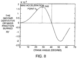
- the second derivative of mass fraction burned as shown in Fig. 8, reaches the point 340 of maximum combustion acceleration after the early flame development at about 10% mass burned and reaches the lowest acceleration at about 90% mass burned.
- the mass fraction burned and cylinder pressure may be determined using the spark plug ion signal, rather than a pressure sensor, according to a procedure 400.
- the ion signal is measured across the spark gap in a cylinder (step 410).
- the starting and end points of the combustion process are determined from the ion signal and the first derivative of the ion signal as described above (step 420).
- the initial manifold pressure is obtained through the intake manifold pressure sensor (MAP sensor) (step 430) and the pressure in the cylinder from the point at which the inlet valve is closed up to the ignition point is determined using the expression provided above (step 440).
- x b 1-exp(- a (( ⁇ - ⁇ 0 )/ ⁇ ) m +1 ) where a and m are constants, ⁇ is the crank angle during the combustion, ⁇ 0 is the crank angle of ignition, and ⁇ is the duration of the combustion.
- the ignition point, combustion termination point, maximum flame acceleration point, and maximum heat release point can be determined from a mathematical evaluation of the measured ion signal as described above.
- the constants a and m may be determined (step 450).
- the mass fraction burned versus crank angle then can be calculated (step 460) using the Wiebe function and the pressure increase due to combustion can be calculated from the mass fraction burned.
- the pressure due to combustion then may be combined with the calculated pressure increase due to cylinder volume change to calculate the total pressure (step 470).
- the mixture in the cylinder may be assumed to be undergoing polytropic compression with a polytropic exponent of 1.3.
- the pressure at the ignition point P ig .
- the pressure change due to combustion and piston motion can be calculated separately. It can be assumed that combustion takes place in a constant volume equal to the volume at the ignition point. By combining the pressure change due to constant volume combustion with the pressure change due to piston movement, the pressure at each crank angle can be estimated.
- the pressure change between the beginning and the end of combustion is:
- the pressure change may depend on the air/fuel ratio and the temperature at the ignition point.
- the expression for pressure change varies only a little and is approximately: ⁇ P ⁇ 3 P ig
- Fig. 10 shows that the cylinder pressure calculated from the measured ion signal is in significant agreement with that obtained from pressure sensor measurements.
- the procedure 400 used to compute cylinder pressure from the ion signal relies on the inflection points in the ion signal and the derivatives of the ion signal rather than on the absolute level of the ion signal. This results in a more accurate determination of cylinder pressure, since the absolute level of the ion signal is subject to fluctuations that are not related to cylinder pressure.
- Fig. 11 shows the ion signal detected by the same RC12LYC spark plug with two different gaps: .040" and .060".
- the signal detected by the spark plug with the larger gap is stronger than the smaller gap signal.
- the gap size is the same, but spark plugs with different projections are used (RC12LYC and RC12YC)
- the shorter projection spark plug measures a much stronger ion signal than the longer projection plug, because there is a greater accumulation of ions near the cylinder wall due to the slower flow of combustion gases.
- the experimental results show that a larger electrode size results in a stronger ion signal.
- the intensity of the ion signal also depends on the electrode surface temperature. For example, a copper core ground electrode, which has a lower electrode surface temperature than other designs, has higher ion intensity. This is because larger or colder electrode surfaces result in a higher ion recombination rate. Unless the ion recombination rate resulting from different electrode designs is considered, the calculation of flame temperature based on the ion signal is not reliable.
Landscapes
- Engineering & Computer Science (AREA)
- Chemical & Material Sciences (AREA)
- Combustion & Propulsion (AREA)
- Physics & Mathematics (AREA)
- General Physics & Mathematics (AREA)
- Mechanical Engineering (AREA)
- General Engineering & Computer Science (AREA)
- Combined Controls Of Internal Combustion Engines (AREA)
- Ignition Installations For Internal Combustion Engines (AREA)
Claims (15)
- Verfahren zum Bestimmen von in einem Zylinder einer Verbrennungskraftmaschine verbranntem Massenanteil, das umfaßt:Messen eines Ionensignals über einen Spalt einer Zündkerze,Ermitteln eines Wendepunkts des Ionensignals undBestimmen von verbranntem Massenanteil unter Verwendung des Wendepunkts.
- Verfahren gemäß Anspruch 1, das ferner die Schritte umfaßt:wobei die Bestimmung des verbrannten Massenanteils eine Berechnung unter Verwendung des Ausdrucks und des Werts für die erste Konstante umfaßt.Darstellen des verbrannten Massenanteils unter Verwendung eines Ausdrucks, der eine erste Konstante einschließt undBestimmen eines Werts für die erste Konstante unter Verwendung des Wendepunkts,
- Verfahren gemäß Anspruch 2, wobei der erste Wendepunkt einem Punkt maximaler Flammbeschleunigung entspricht.
- Verfahren gemäß Anspruch 1, das ferner die Schritte umfaßt:wobei das Bestimmen des verbrannten Massenanteils eine Berechnung unter Verwendung des Ausdrucks und der Werte für die erste und zweite Konstante umfaßt.Ermitteln eines zweiten Wendepunkts des Ionensignals,Darstellen des verbrannten Massenanteils unter Verwendung eines Ausdrucks, der eine erste und zweite Konstante einschließt undBestimmen von Werten für die erste und zweite Konstante unter Verwendung des ersten und zweiten Wendepunkts,
- Verfahren gemäß Anspruch 4, wobei der erste Wendepunkt einem Punkt maximaler Flammbeschleunigung entspricht.
- Verfahren gemäß Anspruch 4, wobei der zweite Wendepunkt einem Punkt maximaler Wärmefreisetzung entspricht.
- Verfahren gemäß Anspruch 1, das ferner das Bestimmen von Druck in dem Zylinder unter Verwendung des verbrannten Massenanteils umfaßt.
- Verfahren zum Bestimmen von in einem Zylinder einer Verbrennungskraftmaschine verbranntem Massenanteil, das umfaßt:Messen eines Ionensignals über einen Spalt einer Zündkerze,Bestimmen eines Punkts maximaler Flammbeschleunigung aus dem gemessenen Ionensignal,Bestimmen eines Punkts maximaler Wärmefreisetzung aus dem gemessenen Ionensignal,Darstellen des verbrannten Massenanteils unter Verwendung eines Ausdrucks, der eine Konstante einschließt; Bestimmen eines Werts für die Konstante unter Verwendung des Punkts maximaler Wärmefreisetzung und des Punkts maximaler Flammbeschleunigung undBestimmen von verbranntem Massenanteil unter Verwendung des Ausdrucks.
- Verfahren gemäß Anspruch 8, das ferner das Bestimmen des Drucks in dem Zylinder umfaßt durch:Bestimmen eines anfänglichen Zylinderdrucks,Bestimmen eines Zündpunkts eines Verbrennungsprozesses aus dem gemessenen Ionensignal,Bestimmen eines Verbrennungsendpunkts aus dem gemessenen Ionensignal,Bestimmen von Druck in dem Zylinder aufgrund von Verbrennung von dem Zündpunkt bis zu dem Verbrennungsendpunkt unter Verwendung des verbrannten Massenanteils,Bestimmen von Druck in dem Zylinder aufgrund von Bewegung eines Kolbens in dem Zylinder von dem Zündpunkt zu dem Verbrennungsendpunkt undBestimmen eines Gesamtdrucks in dem Zylinder von dem Zündpunkt zu dem Verbrennungsendpunkt durch Kombinieren des Drucks aufgrund von Verbrennung mit dem Druck aufgrund von Bewegung des Kolbens in dem Zylinder.
- Vorrichtung zum Messen eines lonensignals einer Zündkerze, wobei die Vorrichtung umfaßt:einen Messschaltkreis, der ausgeführt ist, einen Strom über einen Spalt einer Zündkerze als ein Ionensignal zu messen undeinen Mikroprozessor, der mit dem Messschaltkreis verbunden ist, wobei der Mikroprozessor ausgeführt ist, einen Wendepunkt des Ionensignals zu identifizieren und den verbrannten Massenanteil unter Verwendung des Wendepunkts zu bestimmen.
- Vorrichtung gemäß Anspruch 10, die ferner umfaßt:einen mit Erde verbundenen Widerstand,eine mit dem Widerstand verbundene Spannungsquelle,eine Zündkerze mit einem ersten Spalt, wobei die Zündkerze zwischen Erde und der ersten Spannungsquelle geschaltet ist,einen zweiten Spalt, der mit einem Punkt zwischen der Spannungsquelle und der Zündkerze geschaltet ist und mit einem Zündschaltkreis verbunden ist.
- Vorrichtung gemäß Anspruch 11, die ferner umfaßt:eine Zündspule mit einer primären Spule und einer sekundären Spule, wobei die sekundäre Spule zwischen Erde und dem zweiten Spalt geschaltet ist,eine zweite Spannungsquelle, die mit der primären Spule verbunden ist.
- Vorrichtung gemäß Anspruch 12, wobei der zweite Spalt eine geringere Durchschlagspannung als die Durchschlagspannung der Zündkerze aufweist.
- Vorrichtung gemäß Anspruch 10, wobei der Mikroprozessor ferner ausgelegt ist um:wobei das Bestimmen des verbrannten Massenanteils eine Berechnung unter Verwendung des Ausdrucks und der ersten Konstanten umfaßt.den verbrannten Massenanteil unter Verwendung eines Ausdrucks darzustellen, der eine erste Konstante einschließt, undeinen Wert für die erste Konstante unter Verwendung des ersten Wendepunkts zu bestimmen,
- Verbrennungskraftmaschine, die umfaßt:einen Zylinder,einen Kolben, der ausgeführt ist, sich innerhalb des Zylinders aufwärts und abwärts zu bewegen,eine Zündkerze, die in den Zylinder vorspringt, wobei die Zündkerze einen Spalt aufweist, der ausgeführt ist, ein Treibstoff/Luft-Gemisch in dem Zylinder zu zünden undeinen Ionensignal-Messschaltkreis, der ausgeführt ist, ein Ionensignal über den Spalt der Zündkerze zu messen, einen ersten Wendepunkt des Ionensignal zu ermitteln und den verbrannten Massenanteil unter Verwendung des ersten Wendepunkts zu bestimmen.
Applications Claiming Priority (2)
| Application Number | Priority Date | Filing Date | Title |
|---|---|---|---|
| US883346 | 1997-06-26 | ||
| US08/883,346 US6089077A (en) | 1997-06-26 | 1997-06-26 | Mass fraction burned and pressure estimation through spark plug ion sensing |
Publications (3)
| Publication Number | Publication Date |
|---|---|
| EP0895076A2 EP0895076A2 (de) | 1999-02-03 |
| EP0895076A3 EP0895076A3 (de) | 1999-10-13 |
| EP0895076B1 true EP0895076B1 (de) | 2002-11-13 |
Family
ID=25382424
Family Applications (1)
| Application Number | Title | Priority Date | Filing Date |
|---|---|---|---|
| EP98304395A Expired - Lifetime EP0895076B1 (de) | 1997-06-26 | 1998-06-03 | Erfassung des verbrannten Massenbruchteils und Schätzung des Druckes durch den Ionenstrom der Zündkerze |
Country Status (3)
| Country | Link |
|---|---|
| US (1) | US6089077A (de) |
| EP (1) | EP0895076B1 (de) |
| DE (1) | DE69809345T2 (de) |
Families Citing this family (36)
| Publication number | Priority date | Publication date | Assignee | Title |
|---|---|---|---|---|
| DE19911019C2 (de) * | 1999-03-12 | 2001-02-08 | Daimler Chrysler Ag | Verfahren zur Bestimmung des Luft/Kraftstoff-Verhältnisses in einem Brennraum einer Brennkraftmaschine |
| GB2353070A (en) * | 1999-08-13 | 2001-02-14 | Ford Global Tech Inc | I.c. engine with pre-mixed intake charge and controlled auto-ignition under part-load conditions |
| LU90495B1 (en) * | 1999-12-24 | 2001-06-25 | Delphi Tech Inc | Device and method for ion current sensing |
| EP1113170B1 (de) * | 1999-12-24 | 2005-03-09 | Delphi Technologies, Inc. | Verfahren zur Überwachung des Verbrennungsvorgangs bei der Verbrennung fossiler Brennstoffe |
| LU90494B1 (en) * | 1999-12-24 | 2001-06-25 | Delphi Tech Inc | Glow plug arrangement and method for operating said arrangement |
| US6542798B2 (en) * | 2000-12-06 | 2003-04-01 | Ford Global Technologies, Inc. | Engine ready signal using peak engine cylinder pressure detection |
| GB0112338D0 (en) * | 2001-05-21 | 2001-07-11 | Ricardo Consulting Eng | Improved engine management |
| AT5650U1 (de) * | 2001-10-02 | 2002-09-25 | Avl List Gmbh | Verfahren zur ermittlung der lage einer verbrennung |
| JP3633580B2 (ja) * | 2002-04-17 | 2005-03-30 | 三菱電機株式会社 | 内燃機関の失火検出装置 |
| US6615645B1 (en) | 2002-07-22 | 2003-09-09 | Delphi Technologies, Inc. | System and method for generating a knock determination window for an ion current sensing system |
| JP3894442B2 (ja) * | 2003-05-14 | 2007-03-22 | 三菱電機株式会社 | 内燃機関制御装置 |
| DE102004004162B4 (de) * | 2004-01-28 | 2007-12-27 | Stiebel Eltron Gmbh & Co. Kg | Verfahren und Vorrichtung zur Bestimmung einer Verbrennungsgröße eines Verbrennungsvorgangs |
| WO2005073548A1 (ja) * | 2004-02-02 | 2005-08-11 | Yamaha Hatsudoki Kabushiki Kaisha | エンジンの運転制御装置、それを備えた乗物、エンジンにおける燃焼重心の算出方法、及びエンジンの運転制御方法 |
| DE602004015088D1 (de) * | 2004-05-31 | 2008-08-28 | St Microelectronics Srl | Verfahren zum Berechnen der Hitzefreigabe (HRR) in einer Diesel Brennkraftmaschine mit Common-Rail |
| JP4380604B2 (ja) * | 2005-07-29 | 2009-12-09 | トヨタ自動車株式会社 | 内燃機関の制御装置 |
| US7441537B2 (en) * | 2005-10-18 | 2008-10-28 | Gm Global Technology Operations, Inc. | Method and apparatus to control combustion in a spray-guided direct injection spark-ignited engine |
| US7610900B2 (en) * | 2005-11-03 | 2009-11-03 | Gm Global Technology Operations, Inc. | Method and apparatus for operating a spark-ignited direct fuel injection engine |
| ITMI20061151A1 (it) * | 2006-06-15 | 2007-12-16 | Eldor Corp Spa | Metodo e dispositivi per identificareb le varie fasi della corrente di ionizzazione durante la combustione in un motore a combustione interna |
| US7603226B2 (en) * | 2006-08-14 | 2009-10-13 | Henein Naeim A | Using ion current for in-cylinder NOx detection in diesel engines and their control |
| US7779679B2 (en) * | 2008-04-14 | 2010-08-24 | Gm Global Technology Operations, Inc. | Fuel system diagnostics by analyzing cylinder pressure signal |
| US7735478B1 (en) * | 2008-11-24 | 2010-06-15 | Gm Global Technology Operations, Inc. | Method of calculating mass fraction burnt in an internal combustion engine based on rassweiler-withrow method for real-time applications |
| DE102009029257B3 (de) * | 2009-09-08 | 2010-10-28 | Ford Global Technologies, LLC, Dearborn | Identifikation einer Luft- und/oder Kraftstoffdosierungsabweichung |
| CN102439280B (zh) * | 2010-04-19 | 2014-10-22 | 丰田自动车株式会社 | 内燃机的控制装置 |
| EP2820580A4 (de) * | 2012-02-28 | 2015-07-29 | Univ Wayne State | Verwendung eines ionenstromsignals für techniken zur messung von motorleistung und -emissionen sowie verfahren dafür |
| FR2991450A1 (fr) * | 2012-05-30 | 2013-12-06 | Peugeot Citroen Automobiles Sa | Procede d'estimation de la pression regnant dans une chambre de combustion |
| US10443535B2 (en) * | 2012-09-28 | 2019-10-15 | Wayne State University | Ion current use for combustion resonance detection, reduction and engine control |
| DE102014005866A1 (de) * | 2013-05-09 | 2014-11-13 | Stmicroelectronics S.R.L. | Verfahren und System zum Verarbeiten von Daten von erfasstem Ionisationsstrom für Echtzeitschätzung von Brennraumdruck in einem Motor mit Funkenzündung |
| JP6540424B2 (ja) | 2015-09-24 | 2019-07-10 | 富士通株式会社 | 推定装置、推定方法、推定プログラム、エンジンおよび移動装置 |
| US10077727B2 (en) | 2016-01-13 | 2018-09-18 | GM Global Technology Operations LLC | Engine control systems and methods for nitrogen oxide reduction |
| US9957911B2 (en) | 2016-02-18 | 2018-05-01 | GM Global Technology Operations LLC | Dedicated exhaust gas recirculation control systems and methods |
| DE112016007439B4 (de) | 2016-12-29 | 2025-07-10 | Cummins Inc. | Versorgungsspannung eines gesteuerten Ionisationsstromes |
| CN108343524A (zh) * | 2017-10-12 | 2018-07-31 | 同济大学 | 一种汽油机早燃现象循环内控制系统及其控制方法 |
| JP6958496B2 (ja) * | 2018-06-27 | 2021-11-02 | トヨタ自動車株式会社 | 内燃機関の制御装置 |
| US11365685B2 (en) * | 2020-02-20 | 2022-06-21 | Ford Global Technologies, Llc | Methods and systems for a series gap igniter with a passive prechamber |
| US11280278B2 (en) * | 2020-07-06 | 2022-03-22 | Ford Global Technologies, Llc | Methods and systems for a series gap igniter with a passive pre-chamber |
| AT525903B1 (de) * | 2022-05-18 | 2023-09-15 | Avl List Gmbh | Verfahren zur Klopferkennung in einem Brennraum eines Zylinders |
Family Cites Families (8)
| Publication number | Priority date | Publication date | Assignee | Title |
|---|---|---|---|---|
| US32301A (en) * | 1861-05-14 | Hanger for shafting | ||
| DE2554988C2 (de) | 1975-12-06 | 1985-01-10 | Robert Bosch Gmbh, 7000 Stuttgart | Verfahren zur Bestimmung der Zusammensetzung des einer Brennkraftmaschine zugeführten Betriebsgemisches bzw. des Verbrennungsablaufs des Betriebsgemisches und Einrichtung zur Durchführung des Verfahrens |
| DE2802202C2 (de) * | 1978-01-19 | 1986-09-04 | Robert Bosch Gmbh, 7000 Stuttgart | Einrichtung zur Erfassung von Druckschwankungen im Brennraum einer Brennkraftmaschine |
| DE3006665A1 (de) * | 1980-02-22 | 1981-09-03 | Robert Bosch Gmbh, 7000 Stuttgart | Spannungsquelle zur ionenstrommessung am verbrennungsmotor |
| US4624229A (en) * | 1985-10-29 | 1986-11-25 | General Motors Corporation | Engine combustion control with dilution flow by pressure ratio management |
| EP0358419A3 (de) * | 1988-09-09 | 1990-08-16 | LUCAS INDUSTRIES public limited company | Steuerungssystem für eine Brennkraftmaschine |
| JP2721604B2 (ja) * | 1991-09-30 | 1998-03-04 | 株式会社日立製作所 | 燃焼状態診断装置 |
| US5544635A (en) * | 1993-11-12 | 1996-08-13 | Cosmo Research Institute | Spark-ignition engine and a method of adaptive control on the ignition timing thereof |
-
1997
- 1997-06-26 US US08/883,346 patent/US6089077A/en not_active Expired - Lifetime
-
1998
- 1998-06-03 DE DE69809345T patent/DE69809345T2/de not_active Expired - Lifetime
- 1998-06-03 EP EP98304395A patent/EP0895076B1/de not_active Expired - Lifetime
Also Published As
| Publication number | Publication date |
|---|---|
| EP0895076A3 (de) | 1999-10-13 |
| US6089077A (en) | 2000-07-18 |
| EP0895076A2 (de) | 1999-02-03 |
| DE69809345T2 (de) | 2003-03-20 |
| DE69809345D1 (de) | 2002-12-19 |
Similar Documents
| Publication | Publication Date | Title |
|---|---|---|
| EP0895076B1 (de) | Erfassung des verbrannten Massenbruchteils und Schätzung des Druckes durch den Ionenstrom der Zündkerze | |
| EP1420155B1 (de) | Verfahren zur Regelung der Verbrennungsqualität bei einem magerbetriebenen Verbrennungsmotor | |
| US5769049A (en) | Method and system for controlling combustion engines | |
| JP2929489B2 (ja) | スパーク点火方式内燃エンジンの燃焼監視の方法と装置 | |
| JP3433941B2 (ja) | 内燃エンジンのためのスパーク数可変の多重スパーク点火装置 | |
| US10900461B2 (en) | System and method for monitoring an ignition system | |
| JP2007510092A (ja) | イオン化測定を用い、点火システムを持つ往復圧縮点火エンジンにおける排ガス再循環および燃焼開始を制御する方法および装置 | |
| JPH0587036A (ja) | 燃焼状態診断装置 | |
| Russ et al. | SI engine operation with retarded ignition: Part 2-HC emissions and oxidation | |
| US6550312B1 (en) | Method for determining the air/fuel ratio in an internal combustion engine combustion chamber | |
| JP2000515219A (ja) | 交流電圧点火装置を有する内燃機関におけるノッキング燃焼を認識する方法 | |
| US5492007A (en) | Misfire detection in a spark ignition engine | |
| JP2002161844A (ja) | 燃焼診断及びノック制御のためのシステムを有するオートバイ | |
| US8033165B2 (en) | Method for detecting combustion timing and system thereof | |
| EP3109457B1 (de) | Zündvorrichtung und zündverfahren für einen verbrennungsmotor | |
| US6371078B1 (en) | Method of controlling a direct fuel injection engine and storage medium storing the same | |
| Panousakis et al. | Analysis of SI combustion diagnostics methods using ion-current sensing techniques | |
| Holzberger et al. | Improvement of the EGR Dilution Tolerance in Gasoline Engines by the Use of a HSASI Pre-Chamber Spark Plug | |
| Wislocki | Use of the gas ionization signal for combustion process diagnostics in the cylinder of a spark ignition engine | |
| Yoshimura et al. | Knock and misfire detection using ion current measurement for ultra lean burn medium speed gas engine | |
| Zhao et al. | Engine performance monitoring using spark plug voltage analysis | |
| KR100226232B1 (ko) | 실린더 압력을 이용한 자동차의 점화시기 제어방법 | |
| RU2309334C1 (ru) | Способ контроля и управления сгорания топлива в двс и ионизационный датчик для его осуществления | |
| US5983866A (en) | Diagnostic apparatus and method for a combustion sensor feedback system | |
| Zhao et al. | Engine performance monitoring by means of the spark plug |
Legal Events
| Date | Code | Title | Description |
|---|---|---|---|
| PUAI | Public reference made under article 153(3) epc to a published international application that has entered the european phase |
Free format text: ORIGINAL CODE: 0009012 |
|
| AK | Designated contracting states |
Kind code of ref document: A2 Designated state(s): DE FR GB IT |
|
| AX | Request for extension of the european patent |
Free format text: AL;LT;LV;MK;RO;SI |
|
| PUAL | Search report despatched |
Free format text: ORIGINAL CODE: 0009013 |
|
| AK | Designated contracting states |
Kind code of ref document: A3 Designated state(s): AT BE CH CY DE DK ES FI FR GB GR IE IT LI LU MC NL PT SE |
|
| AX | Request for extension of the european patent |
Free format text: AL;LT;LV;MK;RO;SI |
|
| RIC1 | Information provided on ipc code assigned before grant |
Free format text: 6G 01M 15/00 A, 6G 01L 23/22 B, 6F 02P 5/14 B |
|
| RAP1 | Party data changed (applicant data changed or rights of an application transferred) |
Owner name: FEDERAL MOGUL IGNITION COMPANY |
|
| 17P | Request for examination filed |
Effective date: 20000403 |
|
| AKX | Designation fees paid |
Free format text: AT BE CH CY LI |
|
| RBV | Designated contracting states (corrected) |
Designated state(s): DE FR GB IT |
|
| REG | Reference to a national code |
Ref country code: DE Ref legal event code: 8566 |
|
| GRAG | Despatch of communication of intention to grant |
Free format text: ORIGINAL CODE: EPIDOS AGRA |
|
| 17Q | First examination report despatched |
Effective date: 20011207 |
|
| GRAG | Despatch of communication of intention to grant |
Free format text: ORIGINAL CODE: EPIDOS AGRA |
|
| GRAH | Despatch of communication of intention to grant a patent |
Free format text: ORIGINAL CODE: EPIDOS IGRA |
|
| GRAH | Despatch of communication of intention to grant a patent |
Free format text: ORIGINAL CODE: EPIDOS IGRA |
|
| GRAA | (expected) grant |
Free format text: ORIGINAL CODE: 0009210 |
|
| AK | Designated contracting states |
Kind code of ref document: B1 Designated state(s): DE FR GB IT |
|
| REG | Reference to a national code |
Ref country code: GB Ref legal event code: FG4D |
|
| REF | Corresponds to: |
Ref document number: 69809345 Country of ref document: DE Date of ref document: 20021219 |
|
| ET | Fr: translation filed | ||
| PLBE | No opposition filed within time limit |
Free format text: ORIGINAL CODE: 0009261 |
|
| STAA | Information on the status of an ep patent application or granted ep patent |
Free format text: STATUS: NO OPPOSITION FILED WITHIN TIME LIMIT |
|
| 26N | No opposition filed |
Effective date: 20030814 |
|
| PGFP | Annual fee paid to national office [announced via postgrant information from national office to epo] |
Ref country code: GB Payment date: 20080506 Year of fee payment: 11 |
|
| GBPC | Gb: european patent ceased through non-payment of renewal fee |
Effective date: 20090603 |
|
| PG25 | Lapsed in a contracting state [announced via postgrant information from national office to epo] |
Ref country code: GB Free format text: LAPSE BECAUSE OF NON-PAYMENT OF DUE FEES Effective date: 20090603 |
|
| PGFP | Annual fee paid to national office [announced via postgrant information from national office to epo] |
Ref country code: IT Payment date: 20110616 Year of fee payment: 14 |
|
| PGFP | Annual fee paid to national office [announced via postgrant information from national office to epo] |
Ref country code: FR Payment date: 20120614 Year of fee payment: 15 |
|
| PGFP | Annual fee paid to national office [announced via postgrant information from national office to epo] |
Ref country code: DE Payment date: 20120629 Year of fee payment: 15 |
|
| PG25 | Lapsed in a contracting state [announced via postgrant information from national office to epo] |
Ref country code: IT Free format text: LAPSE BECAUSE OF NON-PAYMENT OF DUE FEES Effective date: 20120603 |
|
| REG | Reference to a national code |
Ref country code: DE Ref legal event code: R119 Ref document number: 69809345 Country of ref document: DE Effective date: 20140101 |
|
| REG | Reference to a national code |
Ref country code: FR Ref legal event code: ST Effective date: 20140228 |
|
| PG25 | Lapsed in a contracting state [announced via postgrant information from national office to epo] |
Ref country code: DE Free format text: LAPSE BECAUSE OF NON-PAYMENT OF DUE FEES Effective date: 20140101 |
|
| PG25 | Lapsed in a contracting state [announced via postgrant information from national office to epo] |
Ref country code: FR Free format text: LAPSE BECAUSE OF NON-PAYMENT OF DUE FEES Effective date: 20130701 |