EP0895014A2 - Process for marking a workpiece with apparatus for conducting the process - Google Patents
Process for marking a workpiece with apparatus for conducting the process Download PDFInfo
- Publication number
- EP0895014A2 EP0895014A2 EP98112630A EP98112630A EP0895014A2 EP 0895014 A2 EP0895014 A2 EP 0895014A2 EP 98112630 A EP98112630 A EP 98112630A EP 98112630 A EP98112630 A EP 98112630A EP 0895014 A2 EP0895014 A2 EP 0895014A2
- Authority
- EP
- European Patent Office
- Prior art keywords
- cutting
- stop
- assembly
- cutting ring
- pipe
- Prior art date
- Legal status (The legal status is an assumption and is not a legal conclusion. Google has not performed a legal analysis and makes no representation as to the accuracy of the status listed.)
- Granted
Links
Images


Classifications
-
- F—MECHANICAL ENGINEERING; LIGHTING; HEATING; WEAPONS; BLASTING
- F16—ENGINEERING ELEMENTS AND UNITS; GENERAL MEASURES FOR PRODUCING AND MAINTAINING EFFECTIVE FUNCTIONING OF MACHINES OR INSTALLATIONS; THERMAL INSULATION IN GENERAL
- F16L—PIPES; JOINTS OR FITTINGS FOR PIPES; SUPPORTS FOR PIPES, CABLES OR PROTECTIVE TUBING; MEANS FOR THERMAL INSULATION IN GENERAL
- F16L19/00—Joints in which sealing surfaces are pressed together by means of a member, e.g. a swivel nut, screwed on or into one of the joint parts
- F16L19/08—Joints in which sealing surfaces are pressed together by means of a member, e.g. a swivel nut, screwed on or into one of the joint parts with metal rings which bite into the wall of the pipe
- F16L19/10—Joints in which sealing surfaces are pressed together by means of a member, e.g. a swivel nut, screwed on or into one of the joint parts with metal rings which bite into the wall of the pipe the profile of the ring being altered
-
- F—MECHANICAL ENGINEERING; LIGHTING; HEATING; WEAPONS; BLASTING
- F16—ENGINEERING ELEMENTS AND UNITS; GENERAL MEASURES FOR PRODUCING AND MAINTAINING EFFECTIVE FUNCTIONING OF MACHINES OR INSTALLATIONS; THERMAL INSULATION IN GENERAL
- F16L—PIPES; JOINTS OR FITTINGS FOR PIPES; SUPPORTS FOR PIPES, CABLES OR PROTECTIVE TUBING; MEANS FOR THERMAL INSULATION IN GENERAL
- F16L2201/00—Special arrangements for pipe couplings
- F16L2201/10—Indicators for correct coupling
Definitions
- the invention relates to a method for marking a Workpiece for the purpose of marking a prescribed and adhered to the assembly process and evidence of an assembly check and thus quality function, in particular of a pipe or Tube end on which at least one cutting ring with at least a cutting edge is pre-assembled, with the cutting ring provided pipe end in a with a conical part and a Pre-assembly tool provided up to this stop is introduced and an axial force on the cutting ring is exercised.
- the pre-assembly When using stainless steel pipes, the pre-assembly is in hardened tools usually prescribed to a proper cutting of the cutting ring in the pipe and thus to ensure a reliable pipe fitting.
- the collar is larger than if the cutting ring only has jammed.
- the waistband is considered absolutely is relatively small, the assessment of the regulations The size of the waistband is only subjectively possible and is special in borderline cases, for example when using of hard pipe materials that only have a small fret exhibit very difficult. A faulty assembly check can also lead to faulty screw connections, which must be avoided under all circumstances.
- the object of the present invention is therefore a safe and objective indication of the existence of a flawless Propose pre-assembly, which is not subjective Characteristics is influenced and can be checked at any time.
- this object is achieved by that the pipe end in the assembly process listed above to the signature on the pre-assembly tool is pressed while the cutting ring through the cuts the force exerted on him into the pipe jacket, whereby by means of the pressing force of the pipe end against the stop of the pre-assembly tool the end of the pipe end at the same time gets an embossing.
- the pressing force for cutting the cutting ring or rings is in the pipe jacket for performing the pre-assembly Invention dimensioned such that sufficient Pressing force between the pipe end and the stop for the embossing pressure is available on the pipe end.
- the circular stop of the pre-assembly connection points according to the invention a raised and / or deepened signature to carry out a pressure embossing during the pre-assembly process on the front of the pipe end to display a Pre-assembly check on.
- the liner has a sublime structure of the Signature used, so that a deepened impression on the Front of the pipe end is created, so that the end face as metallic sealing surface is not affected.
- the force exerted on the cutting ring is advantageously so large dimensions that at the same time as the cutting process of the cutting ring or the cutting rings an embossing pressure on the Front of the pipe end is feasible.
- the stop of the assembly tool an interchangeable disc, a ring disc or a cylinder upstream, which on their the workpiece facing end face each has the defined signature.
- One of these interchangeable pieces is pre-assembled the attack. According to the strength of these usable elements, the stop is shortened so that the same geometrical relationships result.
- a hard powdery or granular material on the face of the stop or the face of the disc or facing the workpiece Firmly apply the cylinder surface in the form of the code to be printed.
- Figure 1 illustrates the balance of power during the Pre-assembly using a mechanical or hydraulic Pre-assembly device.
- the pre-assembly device has a nozzle 1 with a cone 2 which in a cylindrical part 3 for Recording of the pipe end ends.
- Stop surface 4 abuts pipe end 5 during preassembly.
- a union nut 6 exercises on the cutting ring 7 by tightening an axial force which the cutting ring 7 with its Can cut the cutting edges in the pipe jacket, because on the Tube acts against the stop 4 a counterforce.
- the one to apply Fitter is marked with "F”.
- the power with which the pipe end 5 is pressed against the pipe stop 4, is denoted by Fp in Figure 1a.
- the same required Counterforce works in the opposite direction.
- the power Fp is slightly less than the assembly force because of the friction losses subtracted between cutting ring 7 and assembly cone 2 Need to become.
- the force Fp is definitely sufficient around a clear marking on the face of the Stamp the pipe end 5.
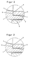
- FIG. 2 has the same section reproduces as Figure 1a, but with the radial Stop surface 4 is equipped with a signature 8, which consists of raised elements.
- a signature 8 which consists of raised elements.
- FIGS. 3 and 4 show further exemplary embodiments with regard to the formation of the embossed characters.
- the signature elements 8 are raised in Figure 2, so that on the Face 9 of the tube end 5 result in recessed embossing.
- FIG. 4 shows embossing elements 11, which have different picture or drawing elements.
- mirrored writing elements can be used train so that after the embossing process a readable Lettering results, which is shown in Figure 5.
- the invention can also be applied to codified features to memorize, for example company identification, information about material identification and times, for example the Manufacturing, so that there is a complete quality control can carry out a simple and safe Proof of quality results.
Landscapes
- Engineering & Computer Science (AREA)
- General Engineering & Computer Science (AREA)
- Mechanical Engineering (AREA)
- Shaping Metal By Deep-Drawing, Or The Like (AREA)
- Turning (AREA)
- Forging (AREA)
- Automatic Assembly (AREA)
Abstract
Description
Die Erfindung betrifft ein Verfahren zur Markierung eines Werkstückes zwecks Kennzeichnung eines vorgeschriebenen und eingehaltenen Montageablaufs und Nachweis einer Montagekontrolle und damit Gütefunktion, insbesondere eines Rohres bzw. Rohrendes, auf dem mindestens ein Schneidring mit mindestens einer Schneide vormontiert wird, wobei das mit dem Schneidring versehene Rohrende in ein mit einem konischen Teil und einem Anschlag versehenen Vormontagewerkzeug bis zu diesem Anschlag eingeführt wird, und auf den Schneidring eine axiale Kraft ausgeübt wird.The invention relates to a method for marking a Workpiece for the purpose of marking a prescribed and adhered to the assembly process and evidence of an assembly check and thus quality function, in particular of a pipe or Tube end on which at least one cutting ring with at least a cutting edge is pre-assembled, with the cutting ring provided pipe end in a with a conical part and a Pre-assembly tool provided up to this stop is introduced and an axial force on the cutting ring is exercised.
In der Praxis ist es üblich Schneidringverschraubungen in gehärteten Werkzeugen vorzumontieren. Hierzu werden hydraulische oder mechanische Geräte verwendet. Es ist auch möglich die Vormontage im Schraubstock von Hand vorzunehmen. Der Vorteil der hydraulischen Montage liegt im geringeren Kraftaufwand während der Montage und in der Tatsache, daß die Montage nicht an unzugänglichen Stellen durchgeführt werden muß.In practice it is common to use compression fittings pre-assemble hardened tools. For this, hydraulic or mechanical devices. It is also possible carry out the pre-assembly in the vice by hand. Of the The advantage of hydraulic assembly is that less effort is required during assembly and in the fact that the Assembly must not be carried out in inaccessible places got to.
Bei der Verwendung von Edelstahlrohren ist die Vormontage in gehärteten Werkzeugen in der Regel vorgeschrieben, um einen ordnungsgemäßen Einschnitt des Schneidringes im Rohr und damit eine zuverlässige Rohrverschraubung zu gewährleisten.When using stainless steel pipes, the pre-assembly is in hardened tools usually prescribed to a proper cutting of the cutting ring in the pipe and thus to ensure a reliable pipe fitting.
Die DIN 3859 Teil 2 und dementsprechend auch die Montageanleitungen
verschiedener Verschraubungshersteller schreiben vor,
daß das Rohr, in das der Schneidring vormontiert werden soll,
vor der Montage gegen den Rohranschlag im Stutzen des Montagewerkzeugs
zu drücken ist. Diese Maßnahme ist erforderlich und
notwendig, da zum Einschneiden des Ringes in das Rohr eine
ausreichende Gegenkraft vorhanden sein muß. Wenn das Rohr
während der Montage nicht am Rohranschlag des Stutzens
anliegt, entsteht eine Fehlmontage. Das Rohr kann sich in
diesem Fall mit dem Schneidring in axialer Richtung weiter
bewegen. Durch den enger werdenden Konus des Stutzens des
Montagewerkzeugs klemmt der Schneidring das Rohr ein, anstatt
es einzuschneiden. Diese Klemmung reicht jedoch nicht aus, um
die geforderte Druckfestigkeit und Dichtheit der Verbindung
zu erzielen. Die Montageanleitungen für Schneidringverbindungen
verlangen den Einschnitt des Schneidringes zu kontrollieren
indem der Bundaufwurf vor dem Schneidring visuell begutachtet
wird. Wenn der Schneidring ordnungsgemäß eingeschnitten
hat, ist der Bundaufwurf größer als wenn der Schneidring nur
geklemmt hat. Da jedoch der Bundaufwurf absolut betrachtet
relativ klein ist, ist die Beurteilung der vorschriftsmäßigen
Größe des Bundaufwurfs nur subjektiv möglich und ist insbesondere
in Grenzfällen, beispielsweise bei der Verwendung
von harten Rohrwerkstoffen, die nur einen kleinen Bundaufwurf
aufweisen, sehr schwierig. Eine fehlerhafte Montagekontrolle
kann aber auch zu fehlerhaften Schraubverbindungen führen,
welche unter allen Umständen vermieden werden müssen.DIN 3859
Aufgabe der vorliegenden Erfindung ist es daher, ein sicheres und objektives Indiz für das Vorliegen einer einwandfreien Vormontage vorzuschlagen, welches nicht von subjektiven Merkmalen beeinflußt wird und jederzeit nachprüfbar ist.The object of the present invention is therefore a safe and objective indication of the existence of a flawless Propose pre-assembly, which is not subjective Characteristics is influenced and can be checked at any time.
Die Lösung dieser Aufgabe besteht nach der Erfindung darin, daß bei dem eingangs aufgeführten Montageverfahren das Rohrende an den mit einer Signatur versehenen Anschlag des Vormontagewerkzeugs gepreßt wird, während der Schneidring durch die auf ihn ausgeübte Kraft in den Rohrmantel einschneidet, wodurch mittels der Preßkraft des Rohrendes gegen den Anschlag des Vormontagewerkzeugs die Stirnseite des Rohrendes gleichzeitig eine Prägung erhält.According to the invention, this object is achieved by that the pipe end in the assembly process listed above to the signature on the pre-assembly tool is pressed while the cutting ring through the cuts the force exerted on him into the pipe jacket, whereby by means of the pressing force of the pipe end against the stop of the pre-assembly tool the end of the pipe end at the same time gets an embossing.
Mit der vorliegenden Erfindung wird daher die Vorschrift ausgenutzt, während des Montagevorganges das Rohrende bis zum Anschlag des Vormontagewerkzeugs zu führen und einen ausreichenden Axialdruck auszuüben. Dieser für eine vorschriftsmäßige Vormontage notwendige Preßdruck wird in vorteilhafter Weise erfindungsgemäß gleichzeitig dafür verwendet, ein Signet auf die Stirnseite des Endes des Rohres zu pressen. Ein solches Signet stellt dann sicher, daß auch für das Einschneiden des oder der Schneidringe ein ausreichender Druck zu Verfügung stand, so daß zwischen der Güte der Vormontage und dem Vorhandensein eines Signets ein funktioneller und eindeutiger Zusammenhang gegeben ist.With the present invention, therefore, the regulation exploited, during the assembly process the pipe end to Of the pre-assembly tool and a sufficient Exert axial pressure. This for a proper one Pre-assembly necessary pressure is more advantageous Way according to the invention simultaneously used for a signet to press on the face of the end of the tube. A such signet then ensures that also for cutting of the cutting ring or rings to a sufficient pressure Was available so that between the quality of the pre-assembly and the presence of a signet a functional and clear Connection is given.
Die Preßkraft für das Einschneiden des oder der Schneidringe in den Rohrmantel zur Durchführung der Vormontage ist nach der Erfindung derartig dimensioniert, daß noch eine ausreichende Preßkraft zwischen Rohrende und Anschlag für den Prägedruck auf das Rohrende zur Verfügung steht.The pressing force for cutting the cutting ring or rings is in the pipe jacket for performing the pre-assembly Invention dimensioned such that sufficient Pressing force between the pipe end and the stop for the embossing pressure is available on the pipe end.
Zwischen der Preßkraft zwischen Rohrende und Anschlag für den Prägedruck und der Einschneidtiefe der Schneide des Schneidringes ist nach der Erfindung ein funktioneller Zusammenhang gegeben, derart, daß bei Vorhandensein des Prägedruckes in jedem Fall die erforderliche Einschneidtiefe der Schneidkanten der Schneidringe erreicht ist, so daß durch den Prägedruck auf der Stirnseite eines Rohres ein objektives Urteil über die Güte der Vormontage gegeben ist.Between the pressing force between the pipe end and the stop for the Embossing pressure and the cutting depth of the cutting edge of the cutting ring is a functional connection according to the invention given such that in the presence of the embossing pressure in the required cutting depth of the cutting edges the cutting rings is reached, so that by the embossing pressure the front of a pipe an objective judgment on the Quality of the pre-assembly is given.
Der kreisringförmige Anschlag des Vormontagestutzens weist nach der Erfindung eine erhabene und/oder vertiefte Signatur zur Durchführung einer Druckprägung während des Vormontagevorganges auf die Stirnseite des Rohrendes zur Anzeige einer Vormontagekontrolle auf. Vorteilhaft wird aber auf der Ringfläche des Einschreibstutzens eine erhabene Struktur der Signatur verwendet, so daß ein vertiefter Abdruck auf der Frontseite des Rohrendes entsteht, so daß die Endfläche als metallische Dichtfläche nicht beeinflußt wird.The circular stop of the pre-assembly connection points according to the invention a raised and / or deepened signature to carry out a pressure embossing during the pre-assembly process on the front of the pipe end to display a Pre-assembly check on. But is advantageous on the ring surface the liner has a sublime structure of the Signature used, so that a deepened impression on the Front of the pipe end is created, so that the end face as metallic sealing surface is not affected.
Die auf den Schneidring ausgeübte Kraft ist vorteilhaft so groß dimensioniert, daß gleichzeitig mit dem Einschneidvorgang des Schneidringes oder der Schneidringe ein Prägedruck auf die Frontseite des Rohrendes durchführbar ist. The force exerted on the cutting ring is advantageously so large dimensions that at the same time as the cutting process of the cutting ring or the cutting rings an embossing pressure on the Front of the pipe end is feasible.
In einer Abwandlung der Erfindung wird dem Anschlag des Montagewerkzeugs eine austauschbare Scheibe, eine Ringscheibe oder ein Zylinder vorgeordnet, welche auf ihrer dem Werkstück zugekehrten Stirnseite jeweils die definierte Signatur aufweist. Eines dieser austauschbaren Stücke wird vor der Vormontage dem Anschlag vorgesetzt. Entsprechend der Stärke dieser einsetzbaren Elemente ist der Anschlag verkürzt, so daß sich die gleichen geometrischen Verhältnisse ergeben.In a modification of the invention, the stop of the assembly tool an interchangeable disc, a ring disc or a cylinder upstream, which on their the workpiece facing end face each has the defined signature. One of these interchangeable pieces is pre-assembled the attack. According to the strength of these usable elements, the stop is shortened so that the same geometrical relationships result.
Für den Aufbau der Signatur läßt sich in einer weiteren Ausführungsform der Erfindung ein hartes pulverförmiges oder granulatförmiges Material auf die Stirnseite des Anschlages oder die dem Werstück zugekehrte Stirnseite der Scheiben- oder Zylinderfläche in Form des aufzudruckenden Codes fest auftragen.For the structure of the signature can be in another Embodiment of the invention a hard powdery or granular material on the face of the stop or the face of the disc or facing the workpiece Firmly apply the cylinder surface in the form of the code to be printed.
Die Erfindung wird anhand der Zeichnungen näher erläutert. Hierbei zeigen:
Figur 1- eine Ansicht mit einem Längs-Teilschnitt eines mechanischen oder hydraulischen Vormontagewerkzeugs mit Werkstück zur Darstellung des Vormontagevorganges nach dem Stand der Technik;
- Figur 1a
- eine vergrößerte Darstellung eines Ausschnittes
aus
Figur 1; Figur 2- eine vergrößerte Darstellung entsprechend der Figur 1a mit einer erhabenen Prägesignatur nach der Erfindung;
Figur 3- eine vergrößerte Darstellung entsprechend der Figur 1a mit einer vertieften Prägesignatur nach der Erfindung;
Figur 4- eine vergrößerte Darstellung entsprechend der Figur 1a mit einer erhabenen Prägesignatur nach der Erfindung in Form bestimmter Zeichen und
Figur 5- eine stirnseitige Ansicht eines mit einer Prägesignatur versehenen Rohrendes.
- Figure 1
- a view with a longitudinal partial section of a mechanical or hydraulic preassembly tool with a workpiece to illustrate the preassembly process according to the prior art;
- Figure 1a
- an enlarged view of a section of Figure 1;
- Figure 2
- an enlarged view corresponding to Figure 1a with a raised embossing signature according to the invention;
- Figure 3
- an enlarged view corresponding to Figure 1a with a deep embossed signature according to the invention;
- Figure 4
- an enlarged view corresponding to Figure 1a with a raised embossing signature according to the invention in the form of certain characters and
- Figure 5
- an end view of a pipe end provided with an embossing signature.
Die Figur 1 veranschaulicht die Kräfteverhältnisse während der
Vormontage mit Hilfe eines mechanischen oder hydraulischen
Vormontagegerätes. Das Vormontagegerät weist einen Stutzen 1
mit einem Konus 2 auf, der in einem zylinderischen Teil 3 zur
Aufnahme des Rohrendes endet. Gegen die radial verlaufende
Anschlagfläche 4 stößt während der Vormontage das Rohrende 5.
Eine Überwurfmutter 6 übt auf den Schneidring 7 durch Anziehen
eine Axialkraft aus, welche den Schneidring 7 mit seinen
Schneidkanten in den Rohrmantel einschneiden läßt, da auf das
Rohr über den Anschlag 4 eine Gegenkraft wirkt. Die aufzubringende
Montagekraft ist mit "F" gekennzeichnet. Die Kraft
mit der das Rohrende 5 gegen den Rohranschlag 4 gedrückt wird,
ist in Figur 1a mit Fp bezeichnet. Die erforderliche gleiche
Gegenkraft, wirkt in die entgegengesetzte Richtung. Die Kraft
Fp ist etwas geringer als die Montagekraft, da die Reibungsverluste
zwischen Schneidring 7 und Montagekonus 2 abgezogen
werden müssen. Die Kraft Fp ist jedoch auf jeden Fall ausreichend,
um eine deutliche Markierung an der Stirnfläche des
Rohrendes 5 aufzuprägen.Figure 1 illustrates the balance of power during the
Pre-assembly using a mechanical or hydraulic
Pre-assembly device. The pre-assembly device has a
Hierzu wird auf Figur 2 verwiesen, welche einen gleichen Ausschnitt
wiedergibt wie Figur 1a, wobei jedoch die radiale
Anschlagfläche 4 mit einer Signatur 8 ausgerüstet ist, welche
aus erhabenen Elementen besteht. Mit dem Einschneidvorgang des
Schneidringes 7 in den Rohrmantel 5 preßen sich die Elemente
8 in die Stirnseite 9 des Rohrendes 5 ein. Der Einschneidvorgang
des Schneidringes 7 bedingt daher gleichzeitig auch den
Preßvorgang der Elemente 8 in die Stirnseite 9 des Rohrendes
5, womit sichergestellt ist, daß bei Vorhandensein eines
Signets auf der Rohrstirnseite auch der vorschriftsmäßige
Einschneidvorgang stattgefunden hat. Damit liegt eine objektive
Montagekontrolle und ein Beweis für eine vorschriftsmäßige
Vormontage vor, welche deutlich erkennbar ist.For this purpose, reference is made to FIG. 2, which has the same section
reproduces as Figure 1a, but with the
Die Figuren 3 und 4 zeigen weitere Ausführungsbeispiele bezüglich
der Ausbildung der Prägezeichen. Die Signaturelemente 8
sind in Figur 2 erhaben ausgebildet, so daß sich auf der
Stirnseite 9 des Rohrendes 5 vertiefte Prägungen ergeben.FIGS. 3 and 4 show further exemplary embodiments with regard to
the formation of the embossed characters. The
In Figur 3 sind die Prägezeichen auf der Anschlagfläche 4
vertieft ausgebildet, so daß sich auf dem Rohrende 5 erhabene
Elemente ergeben. Die Figur 4 gibt Prägeelemente 11 wieder,
welche unterschiedliche Bild- oder Zeichenelemente aufweisen.
Beispielsweise lassen sich spiegelverkehrte Schriftelemente
ausbilden, so daß sich nach dem Prägevorgang ein lesbarer
Schriftzug ergibt, welcher in Figur 5 dargestellt ist.In Figure 3, the embossed characters are on the
Die Erfindung läßt sich auch anwenden, um codifizierte Merkmale einzuprägen, beispielsweise Firmenkennzeichen, Angaben über Materialkennzeichen und Zeitangaben, beispielsweise der Herstellung, so daß sich damit eine lückenlose Qualitätskontrolle durchführen läßt, welche einen einfachen und sicheren Qualitätsnachweis ergibt. The invention can also be applied to codified features to memorize, for example company identification, information about material identification and times, for example the Manufacturing, so that there is a complete quality control can carry out a simple and safe Proof of quality results.
- 11
- StutzenSupport
- 22nd
- Konuscone
- 33rd
- zylindrischer Teil des Stutzenscylindrical part of the nozzle
- 44th
- Anschlagfläche im StutzenStop surface in the nozzle
- 55
- RohrendePipe end
- 66
- ÜberwurfmutterCap nut
- 77
- SchneidringCutting ring
- 88th
- Elementeelements
- 99
- Stirnseite des RohresFace of the tube
Claims (9)
Applications Claiming Priority (2)
| Application Number | Priority Date | Filing Date | Title |
|---|---|---|---|
| DE19732757 | 1997-07-30 | ||
| DE19732757A DE19732757C1 (en) | 1997-07-30 | 1997-07-30 | Method for marking a workpiece with device for carrying out the method |
Publications (3)
| Publication Number | Publication Date |
|---|---|
| EP0895014A2 true EP0895014A2 (en) | 1999-02-03 |
| EP0895014A3 EP0895014A3 (en) | 2001-01-31 |
| EP0895014B1 EP0895014B1 (en) | 2003-09-24 |
Family
ID=7837334
Family Applications (1)
| Application Number | Title | Priority Date | Filing Date |
|---|---|---|---|
| EP98112630A Expired - Lifetime EP0895014B1 (en) | 1997-07-30 | 1998-07-08 | Process for marking a workpiece with apparatus for conducting the process |
Country Status (3)
| Country | Link |
|---|---|
| EP (1) | EP0895014B1 (en) |
| AT (1) | ATE250738T1 (en) |
| DE (2) | DE19732757C1 (en) |
Cited By (7)
| Publication number | Priority date | Publication date | Assignee | Title |
|---|---|---|---|---|
| WO2013139641A1 (en) * | 2012-03-21 | 2013-09-26 | Voss Fluid Gmbh | Mounting system for pipe screw connections having a cutting ring |
| US10024468B2 (en) | 2014-05-09 | 2018-07-17 | Swagelok Company | Conduit fitting with components adapted for facilitating assembly |
| US10215315B2 (en) | 2008-09-05 | 2019-02-26 | Parker-Hannifin Corporation | Tube compression fitting and flared fitting used with connection body and method of making same |
| US10584814B2 (en) | 2016-03-23 | 2020-03-10 | Swagelok Company | Conduit fitting with stroke resisting features |
| US10648598B2 (en) | 2016-02-09 | 2020-05-12 | Swagelok Company | Ferrule for a conduit fitting |
| USRE49416E1 (en) | 2009-11-20 | 2023-02-14 | Corning Incorporated | Optical fiber illumination systems and methods |
| US11703165B2 (en) | 2018-04-27 | 2023-07-18 | Swagelok Company | Ferrule assembly for conduit fitting |
Families Citing this family (1)
| Publication number | Priority date | Publication date | Assignee | Title |
|---|---|---|---|---|
| DE10011146A1 (en) * | 2000-03-07 | 2001-09-27 | Parker Hannifin Gmbh | Pipe connection system comprises connector, union nut and compression ring which is locked into a conical bore in the connector by union nut, face of ring which faces nut having reinforcement consisting of narrow sections of ring |
Family Cites Families (7)
| Publication number | Priority date | Publication date | Assignee | Title |
|---|---|---|---|---|
| US2330841A (en) * | 1941-03-14 | 1943-10-05 | Arthur L Parker | Tube coupling |
| US3471181A (en) * | 1966-10-13 | 1969-10-07 | Imp Eastman Corp | Fitting |
| FR2022430A1 (en) * | 1968-11-02 | 1970-07-31 | Biagi Mario | |
| US3893716A (en) * | 1974-04-01 | 1975-07-08 | Weatherhead Co | Flareless fitting |
| US4022499A (en) * | 1975-04-14 | 1977-05-10 | Aeroquip Corporation | Tube retaining compression fitting |
| GB2220716B (en) * | 1988-06-17 | 1992-06-03 | Vetco Gray U K Limited | An indicator system for threaded connections |
| US4962579A (en) * | 1988-09-02 | 1990-10-16 | Exxon Production Research Company | Torque position make-up of tubular connections |
-
1997
- 1997-07-30 DE DE19732757A patent/DE19732757C1/en not_active Expired - Fee Related
-
1998
- 1998-07-08 EP EP98112630A patent/EP0895014B1/en not_active Expired - Lifetime
- 1998-07-08 DE DE59809695T patent/DE59809695D1/en not_active Expired - Fee Related
- 1998-07-08 AT AT98112630T patent/ATE250738T1/en not_active IP Right Cessation
Non-Patent Citations (1)
| Title |
|---|
| None |
Cited By (12)
| Publication number | Priority date | Publication date | Assignee | Title |
|---|---|---|---|---|
| US10215315B2 (en) | 2008-09-05 | 2019-02-26 | Parker-Hannifin Corporation | Tube compression fitting and flared fitting used with connection body and method of making same |
| USRE49416E1 (en) | 2009-11-20 | 2023-02-14 | Corning Incorporated | Optical fiber illumination systems and methods |
| WO2013139641A1 (en) * | 2012-03-21 | 2013-09-26 | Voss Fluid Gmbh | Mounting system for pipe screw connections having a cutting ring |
| CN104204641A (en) * | 2012-03-21 | 2014-12-10 | 福士流体有限公司 | Mounting system for pipe screw connections having a cutting ring |
| US10024468B2 (en) | 2014-05-09 | 2018-07-17 | Swagelok Company | Conduit fitting with components adapted for facilitating assembly |
| US11079046B2 (en) | 2014-05-09 | 2021-08-03 | Swagelok Company | Conduit fitting with components adapted for facilitating assembly |
| US12072044B2 (en) | 2014-05-09 | 2024-08-27 | Swagelok Company | Conduit fitting with components adapted for facilitating assembly |
| US10648598B2 (en) | 2016-02-09 | 2020-05-12 | Swagelok Company | Ferrule for a conduit fitting |
| US11519531B2 (en) | 2016-02-09 | 2022-12-06 | Swagelok Company | Ferrule for a conduit fitting |
| US10584814B2 (en) | 2016-03-23 | 2020-03-10 | Swagelok Company | Conduit fitting with stroke resisting features |
| US11009158B2 (en) | 2016-03-23 | 2021-05-18 | Swagelok Company | Conduit fitting with stroke resisting features |
| US11703165B2 (en) | 2018-04-27 | 2023-07-18 | Swagelok Company | Ferrule assembly for conduit fitting |
Also Published As
| Publication number | Publication date |
|---|---|
| ATE250738T1 (en) | 2003-10-15 |
| EP0895014A3 (en) | 2001-01-31 |
| EP0895014B1 (en) | 2003-09-24 |
| DE19732757C1 (en) | 1999-03-11 |
| DE59809695D1 (en) | 2003-10-30 |
Similar Documents
| Publication | Publication Date | Title |
|---|---|---|
| DE19620165C1 (en) | Method and device for producing a pipe press connection | |
| DE102005056378A1 (en) | Insertion and anchoring process for connecting element in workpiece involves jointing connecting element to workpiece via seeking and/or centering element | |
| EP0715708B1 (en) | Pressing tool | |
| EP0895014B1 (en) | Process for marking a workpiece with apparatus for conducting the process | |
| EP0717205B1 (en) | Fastening device | |
| DE19945113A1 (en) | Process for connecting a press fitting to a pipe and press fitting, pipe and pressing device for carrying out this process | |
| DE10259369B3 (en) | Device to set punch rivet in metal plates has upper sleeve with sliding die, lower stationary die to hold rivet shaft during setting, and enclosing tensioning sleeve to support metal plates | |
| DE2120059C3 (en) | Connection means for the high-strength connection of components, in particular aircraft components | |
| EP1064488B1 (en) | Pipe connection | |
| DE102008024938A1 (en) | Stanznietwerkzeug | |
| DE4118941A1 (en) | Hub shaft connection with pressure ring and tension ring - has socket sleeve in-between avoiding damage with excessive torque | |
| EP0908252A2 (en) | Method and device for controling wear of crimping pliers | |
| EP3158209B1 (en) | Process to press a ball in a first workpiece | |
| DE4237219A1 (en) | Pipe connector with alignment control - has split sleeved connector with outer thread rotating on end of male connector | |
| DE10126180C1 (en) | End-side closure of a pipe | |
| EP1086761B1 (en) | Method and device for checking wear of crimping pliers | |
| AT506831B1 (en) | METHOD FOR CALIBRATING BEARING BUSHES | |
| DE19616975A1 (en) | Method for checking applied pressure of crimping tools | |
| DE102015209531B4 (en) | Method for producing a component connection | |
| DE3402583C2 (en) | Process for creating a pipe connection and a suitable pipe connection device | |
| DE102021108510A1 (en) | Flange connection and assembly quality control procedures | |
| DE4019467A1 (en) | Fastening two metal sheets together - by forcing pin through sheets under isostatic pressure | |
| DE10026083C1 (en) | Pipe compression joint has cylindrical metal compression fitting element clamped to inserted pipe end via pressure ring engaged by compression tool | |
| DE19503253C2 (en) | Assembly rivet bushing and assembly method | |
| DE19902732C2 (en) | Device for connecting two line pipes of different line pipe systems |
Legal Events
| Date | Code | Title | Description |
|---|---|---|---|
| PUAI | Public reference made under article 153(3) epc to a published international application that has entered the european phase |
Free format text: ORIGINAL CODE: 0009012 |
|
| AK | Designated contracting states |
Kind code of ref document: A2 Designated state(s): AT DE FI FR GB IT SE |
|
| AX | Request for extension of the european patent |
Free format text: AL;LT;LV;MK;RO;SI |
|
| PUAL | Search report despatched |
Free format text: ORIGINAL CODE: 0009013 |
|
| AK | Designated contracting states |
Kind code of ref document: A3 Designated state(s): AT BE CH CY DE DK ES FI FR GB GR IE IT LI LU MC NL PT SE |
|
| AX | Request for extension of the european patent |
Free format text: AL;LT;LV;MK;RO;SI |
|
| 17P | Request for examination filed |
Effective date: 20010126 |
|
| AKX | Designation fees paid |
Free format text: AT DE FI FR GB IT SE |
|
| GRAH | Despatch of communication of intention to grant a patent |
Free format text: ORIGINAL CODE: EPIDOS IGRA |
|
| GRAS | Grant fee paid |
Free format text: ORIGINAL CODE: EPIDOSNIGR3 |
|
| GRAA | (expected) grant |
Free format text: ORIGINAL CODE: 0009210 |
|
| AK | Designated contracting states |
Kind code of ref document: B1 Designated state(s): AT DE FI FR GB IT SE |
|
| PG25 | Lapsed in a contracting state [announced via postgrant information from national office to epo] |
Ref country code: IT Free format text: LAPSE BECAUSE OF FAILURE TO SUBMIT A TRANSLATION OF THE DESCRIPTION OR TO PAY THE FEE WITHIN THE PRESCRIBED TIME-LIMIT;WARNING: LAPSES OF ITALIAN PATENTS WITH EFFECTIVE DATE BEFORE 2007 MAY HAVE OCCURRED AT ANY TIME BEFORE 2007. THE CORRECT EFFECTIVE DATE MAY BE DIFFERENT FROM THE ONE RECORDED. Effective date: 20030924 Ref country code: GB Free format text: LAPSE BECAUSE OF FAILURE TO SUBMIT A TRANSLATION OF THE DESCRIPTION OR TO PAY THE FEE WITHIN THE PRESCRIBED TIME-LIMIT Effective date: 20030924 Ref country code: FR Free format text: LAPSE BECAUSE OF FAILURE TO SUBMIT A TRANSLATION OF THE DESCRIPTION OR TO PAY THE FEE WITHIN THE PRESCRIBED TIME-LIMIT Effective date: 20030924 Ref country code: FI Free format text: LAPSE BECAUSE OF FAILURE TO SUBMIT A TRANSLATION OF THE DESCRIPTION OR TO PAY THE FEE WITHIN THE PRESCRIBED TIME-LIMIT Effective date: 20030924 |
|
| REG | Reference to a national code |
Ref country code: GB Ref legal event code: FG4D Free format text: NOT ENGLISH |
|
| REF | Corresponds to: |
Ref document number: 59809695 Country of ref document: DE Date of ref document: 20031030 Kind code of ref document: P |
|
| PG25 | Lapsed in a contracting state [announced via postgrant information from national office to epo] |
Ref country code: SE Free format text: LAPSE BECAUSE OF FAILURE TO SUBMIT A TRANSLATION OF THE DESCRIPTION OR TO PAY THE FEE WITHIN THE PRESCRIBED TIME-LIMIT Effective date: 20031224 |
|
| GBV | Gb: ep patent (uk) treated as always having been void in accordance with gb section 77(7)/1977 [no translation filed] |
Effective date: 20030924 |
|
| PG25 | Lapsed in a contracting state [announced via postgrant information from national office to epo] |
Ref country code: AT Free format text: LAPSE BECAUSE OF NON-PAYMENT OF DUE FEES Effective date: 20040708 |
|
| PLBE | No opposition filed within time limit |
Free format text: ORIGINAL CODE: 0009261 |
|
| STAA | Information on the status of an ep patent application or granted ep patent |
Free format text: STATUS: NO OPPOSITION FILED WITHIN TIME LIMIT |
|
| 26N | No opposition filed |
Effective date: 20040625 |
|
| EN | Fr: translation not filed | ||
| PG25 | Lapsed in a contracting state [announced via postgrant information from national office to epo] |
Ref country code: DE Free format text: LAPSE BECAUSE OF NON-PAYMENT OF DUE FEES Effective date: 20050201 |