EP0894579A1 - Drill stand, particularly for stone drills, with a water suction ring - Google Patents
Drill stand, particularly for stone drills, with a water suction ring Download PDFInfo
- Publication number
- EP0894579A1 EP0894579A1 EP98113390A EP98113390A EP0894579A1 EP 0894579 A1 EP0894579 A1 EP 0894579A1 EP 98113390 A EP98113390 A EP 98113390A EP 98113390 A EP98113390 A EP 98113390A EP 0894579 A1 EP0894579 A1 EP 0894579A1
- Authority
- EP
- European Patent Office
- Prior art keywords
- water suction
- suction ring
- drilling machine
- machine stand
- stand according
- Prior art date
- Legal status (The legal status is an assumption and is not a legal conclusion. Google has not performed a legal analysis and makes no representation as to the accuracy of the status listed.)
- Granted
Links
Images


Classifications
-
- B—PERFORMING OPERATIONS; TRANSPORTING
- B25—HAND TOOLS; PORTABLE POWER-DRIVEN TOOLS; MANIPULATORS
- B25H—WORKSHOP EQUIPMENT, e.g. FOR MARKING-OUT WORK; STORAGE MEANS FOR WORKSHOPS
- B25H1/00—Work benches; Portable stands or supports for positioning portable tools or work to be operated on thereby
- B25H1/0021—Stands, supports or guiding devices for positioning portable tools or for securing them to the work
- B25H1/0057—Devices for securing hand tools to the work
- B25H1/0064—Stands attached to the workpiece
-
- B—PERFORMING OPERATIONS; TRANSPORTING
- B23—MACHINE TOOLS; METAL-WORKING NOT OTHERWISE PROVIDED FOR
- B23Q—DETAILS, COMPONENTS, OR ACCESSORIES FOR MACHINE TOOLS, e.g. ARRANGEMENTS FOR COPYING OR CONTROLLING; MACHINE TOOLS IN GENERAL CHARACTERISED BY THE CONSTRUCTION OF PARTICULAR DETAILS OR COMPONENTS; COMBINATIONS OR ASSOCIATIONS OF METAL-WORKING MACHINES, NOT DIRECTED TO A PARTICULAR RESULT
- B23Q11/00—Accessories fitted to machine tools for keeping tools or parts of the machine in good working condition or for cooling work; Safety devices specially combined with or arranged in, or specially adapted for use in connection with, machine tools
- B23Q11/10—Arrangements for cooling or lubricating tools or work
-
- B—PERFORMING OPERATIONS; TRANSPORTING
- B28—WORKING CEMENT, CLAY, OR STONE
- B28D—WORKING STONE OR STONE-LIKE MATERIALS
- B28D1/00—Working stone or stone-like materials, e.g. brick, concrete or glass, not provided for elsewhere; Machines, devices, tools therefor
- B28D1/02—Working stone or stone-like materials, e.g. brick, concrete or glass, not provided for elsewhere; Machines, devices, tools therefor by sawing
- B28D1/04—Working stone or stone-like materials, e.g. brick, concrete or glass, not provided for elsewhere; Machines, devices, tools therefor by sawing with circular or cylindrical saw-blades or saw-discs
- B28D1/041—Working stone or stone-like materials, e.g. brick, concrete or glass, not provided for elsewhere; Machines, devices, tools therefor by sawing with circular or cylindrical saw-blades or saw-discs with cylinder saws, e.g. trepanning; saw cylinders, e.g. having their cutting rim equipped with abrasive particles
Definitions
- the invention relates to a drill stand, in particular for Rock drill, with a base plate and a pedestal, on the one Carriage with a receptacle for a drill is guided, the Drilling axis can be aligned to a work surface, and with a water suction ring, which has an elastic sealing ring and opposite Drill stand is kept movable and can be removed from it.
- the drilling axis is on the Center of gravity of the footplate opposite side of the pillar, so that a hole is drilled in the footprint of the stand can be, even in room corners.
- the footprint is there made of natural and artificial stone, concrete and.
- the term "pedestal” does not mean that its axis is in operation must be vertical; the pillar can rather be compared to the Footplate can be swiveled, and the footplate can be used on both floors as well as on walls and undersides of the ceiling, i.e. in an overhead position, be attached.
- the base plate is usually by means of a Vacuum device or a dowel connection as close as possible to the hole to be produced is connected to the surface to be drilled.
- the Footprint is therefore more appropriately referred to as a "work surface”.
- the invention is therefore based on the object of a drill stand of the genus described above, in which the Water suction ring easy to assemble and (for transport purposes) too disassemble and still a reliable compared to the footplate Creates a connection that cannot be unintentionally broken by external forces can and which maintains the sealing effect against the work surface.
- Characteristic A ensures that the position of the water suction ring can be set specifically against the footplate, by each of the clamping spindles individually. As far as the tolerances are sufficient, to a certain extent it becomes an adjustable and defined one Cardan joint formed.
- the projections according to feature B) ensure that the points of attack the pawls as close as possible to a diameter line of the Water suction rings are placed, the diameter line being one of the Axes of the gimbal is.
- Characteristic C ensures that the interaction of Tensioning spindles and the locking pawls swivel or swivel joints are formed become.
- the compression springs according to feature D) ensure that the water suction ring can be pressed onto the work surface with adjustable preloads is, whereby a precisely guided self-adjustment of the water suction ring opposite the work surface.
- Feature E defines two simple alternative solutions for the Attachment and the direction of action of the latches.
- the feature F creates the conditions for simple operation the latches by finger pressure.
- Feature G teaches a simplifying double function of leveling spindles and holding pin.
- the Mermal H creates additional security against an unwanted Loosen the latches.
- the mobility at other points in the connections the pawls are not affected.
- the feature I) creates a simple storage of the compression springs on the Clamping spindles.
- the feature J) improves the mobility around the diameter line and about an imaginary joint axis perpendicular to this.
- the feature K) cheapens the manufacture and reduces the weight of what is particularly advantageous for overhead work.
- Feature L makes it possible to engage the drilling axis in room corners improved.
- FIG. 1 and 2 is a base plate 1 with a virtual reference plane E-E shown, the four leveling spindles 2 in a horizontal position can be brought, for example, parallel to a work surface 3.
- a vacuum suction device can be accommodated in a chamber 4.
- the base plate 1 can be made using an elongated hole 5, a dowel and a clamping screw on or on the work surface 3 are attached.
- a The centering lever shown in more detail in FIG. 3 can be pivoted via a rotary knob 10.
- a lockable stand column 8 On the base plate 1 is by means of two pedestals 6 and a pivot axis 7 a lockable stand column 8 arranged on its other side End carries a handle 9.
- the column 8 To this end the column 8 have a linear row of teeth 13 and the slide one Shaft 14 with a pinion, not shown here, by one of a Side to the other removable hand lever 15 is drivable.
- the wave 14 is lockable by a locking bolt 14a and runs at it Downward movement against an adjustable stop body 11a.
- the standing column 8 has two on diametrically opposite sides trapezoidal guide grooves 16, on the bottom of which a scale 17 is arranged.
- the leadership happens via complementary trapezoidal prismatic sliding body 18 ( Figure 2) using four clamping screws 19 are braced against the column 8.
- Figure 2 complementary trapezoidal prismatic sliding body 18 ( Figure 2) using four clamping screws 19 are braced against the column 8.
- the footplate 1 has a footplate longitudinal axis AF-AF, which together with the AS-AS column axis Plane of symmetry defined.
- a part-circular recess 22 which is the drilling axis AB-AB runs concentrically.
- One on Slide 11 mounted spirit level 23 is used to level the footplate 1 with the vertical column 8, the finding opposite the base plate 1 is made possible by a tension lever 24.
- a water suction ring 25 with an annular chamber body 26 a plastic.
- This has a soft, elastomeric underside Sealing ring 27 and a dash-dotted line shown on its top Perforated membrane 28 made of an elastomeric material with a concentric Center opening 29 for the passage of a drill, not shown with the drilling axis AB.
- the chamber body 26 has diametrically opposite Sides of an AF-AF running perpendicular to the longitudinal axis of the footplate Diameter line D-D two molded eyes 30 and 31 with inserted Bushings 32 made of metal, through which a clamping spindle 33 and 34 is passed through.
- the inner bores of the bushes 32 allow a limited pivoting movement of the water suction ring 25 on the clamping spindles 33 and 34 around the diameter line D-D.
- the Clamping spindles 33 and 34 in a mirror-image arrangement each have a latch 35 and 36 mounted, which is designed as a double lever and a locking arm 35a and 36a and an actuating arm 35b and 36b.
- the locking arms 35a and 36a have bevels 35c and 36c and locking recesses 35d and 36d.
- the latches are by means of the actuating arms 35b and 36b 35 and 36 against the force of a return spring 37 and 38 in one Plane pivotable, which runs parallel to the reference plane E-E ( Figure 1).
- the water suction ring 25 is released by pressing the actuating arms 35b and 36b.
- This process is shown in Figure 3, above, by the Arrow P indicated.
- the latches 35 and 36 clamped on the base plate 1 by knurled nuts 41.
- the clamping spindles 33 and 34 each have a shoulder surface 34a, against which a compression spring 42 is supported. The other end presses on the respective eye 30 or 31 by means of the socket 32 Ends of the clamping spindles 33 and 34 are by means of threads, not shown stored in the latches 35 and 36. This can cause the preload the compression springs 42 and thus the contact pressure of the sealing ring 27 on the Work surface 3 ( Figure 1) can be changed.
- Tensioning spindle 33 and / or 34 can be adjusted accordingly to a stop unwanted water drainage.
- the arrangement has been made so that there is a gap "S" between the undersides of the eyes 30 and 31 remains a few millimeters.
- This provides the suspension for the water suction ring 25 the effect of a gimbal joint with two axes, one parallel to the diameter line D-D and the other parallel to Longitudinal axis of the footplate AF-AF runs. This effect supports elasticity the sealing ring 27.
- Figure 3 can still be seen that on the underside of the base plate 1 and on the circumference of the recess 22 a geometrically similar curved one Centering lever 43 is arranged, the free end 44 about a pivot 45 to the drilling axis AB is pivotable to the drill stand to be able to center exactly.
- the pivot 45 is with the Knob 10 connected ( Figure 1).
- the central position of the centering lever 43 is defined by a stop 46.
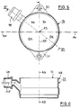
- FIG. 5 and 6 is the substantially cylindrical chamber body 26 with the molded eyes 30 and 31 shown in more detail. He owns its annular upper edge 47 a circumferential annular bead 48 on the the perforated membrane 28 made of rubber (FIG. 4) can be put on by carding is. Furthermore, the chamber body 26, which one in four Quadrants Q1, Q2, Q3 and Q4 can think divided into the quadrant Q4 a connecting piece 49 for a suction line 50 ( Figure 7). This Connection piece 49 is bent upwards so that it connects to the suction line 50 lies above the base plate 1. Quadrants Q3 and Q4 are the Stand column 8 facing.
- the axis AR of the connection piece is aligned radially, and the angle between the axis AR and the diameter line D-D is between 45 ° and 60 °, preferably about 53 °.
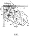
- FIG. 7 shows the example of working with a device according to the invention using a drill bit with a diameter of 130 mm in a corner of a room between two walls 51 and 52.
- the contours the eyes not shown here and the latches, or their projection on the work surface 3 is chosen so that no disability entry; in particular, the actuating arms 35b and 36b are not unintentionally adjusted.
- a drill 53 is also indicated in FIG.
- drilling is not just a hand drill understand, but each drilling unit with a drive motor, one Reduction gear and a fastening device for a drill, even when this drilling unit is constantly with the slide 11 is connected.
Abstract
Description
Die Erfindung betrifft einen Bohrmaschinenständer, insbesondere für Gesteinsbohrer, mit einer Fußplatte und einer Standsäule, an der ein Schlitten mit einer Aufnahme für eine Bohrmaschine geführt ist, deren Bohrachse auf eine Arbeitsfläche ausrichtbar ist, und mit einem Wasserabsaugring, der einen elastischen Dichtring aufweist und gegenüber dem Bohrmaschinenständer beweglich gehalten und von diesem abnehmbar ist.The invention relates to a drill stand, in particular for Rock drill, with a base plate and a pedestal, on the one Carriage with a receptacle for a drill is guided, the Drilling axis can be aligned to a work surface, and with a water suction ring, which has an elastic sealing ring and opposite Drill stand is kept movable and can be removed from it.
Sei Bohrmaschinenständern dieser Art liegt die Bohrachse auf der dem Flächenschwerpunkt der Fußplatte gegenüberliegenden Seite der Standsäule, damit in die Aufstellfläche des Ständers eine Bohrung eingebracht werden kann, und zwar auch in Raumecken. Die Aufstellfläche besteht dabei aus Natur- und Kunststein, aus Beton u. dgl. Als Bohrer kommen vorzugsweise Diamant-Bohrkronen, sog. "Kernbohrer" infrage, die während des Bohrens durch große Wassermengen gekühlt werden müssen. Hierfür sind eine Wasserzufuhr und ein Wasserabsaugring vorgesehen, der für Über-Kopf-Arbeiten sogar zwingend vorgeschrieben ist. Be this type of drill stand, the drilling axis is on the Center of gravity of the footplate opposite side of the pillar, so that a hole is drilled in the footprint of the stand can be, even in room corners. The footprint is there made of natural and artificial stone, concrete and. Like. Preferably come as drills Diamond core bits, so-called "core drills" in question during the Drilling must be cooled by large amounts of water. For this are a water supply and a water suction ring are provided for overhead work is even mandatory.
Der Ausdruck "Standsäule" besagt nicht, daß deren Achse beim Betrieb senkrecht stehen muß; die Standsäule kann vielmehr gegenüber der Fußplatte schwenkbar sein, und die Fußplatte kann sowohl auf Fußböden als auch an Wänden und Deckenunterseiten, also in Über-Kopf-Lage, angebracht werden. Dabei wird in der Regel die Fußplatte mittels einer Vakuumeinrichtung oder einer Dübelverbindung in größtmöglicher Nähe der herzustellenden Bohrung mit der anzubohrenden Fläche verbunden. Die Aufstellfläche wird daher zutreffender als "Arbeitsfläche" bezeichnet.The term "pedestal" does not mean that its axis is in operation must be vertical; the pillar can rather be compared to the Footplate can be swiveled, and the footplate can be used on both floors as well as on walls and undersides of the ceiling, i.e. in an overhead position, be attached. The base plate is usually by means of a Vacuum device or a dowel connection as close as possible to the hole to be produced is connected to the surface to be drilled. The Footprint is therefore more appropriately referred to as a "work surface".
Ein Problem besteht hierbei bezüglich der - lösbaren - Verbindung mit dem Wasserabsaugring, der an seiner unteren Umlaufkante einen weichen, elastomeren Dichtungsring trägt. Dieser soll auch dann einen Wasseraustritt gegenüber der Arbeitsfläche verhindern, wenn diese uneben ist, z.B. durch unregelmäßig verlegte Boden- oder Wandplatten (Fugensprünge), durch Welligkeiten in der Arbeitsfläche und/oder durch eine Schiefstellung der Arbeitsfläche gegenüber der Bohrachse. Der elastomere Dichtungsring trägt bereits - begrenzt - zum Ausgleich dieser Bodenunebenheiten bei.There is a problem with the - releasable - connection with the Water suction ring, which has a soft, wearing elastomeric sealing ring. This should also allow water to escape prevent the work surface from being uneven, e.g. due to irregularly laid floor or wall panels (cracks in the joints), due to ripples in the work surface and / or an inclined position the working surface opposite the drilling axis. The elastomeric sealing ring already helps - to a limited extent - to compensate for these uneven floors.
Durch einen Katalog der Anmelderin "Lieferprogramm Diamanttechnik
"95/96", Seiten 3, 6, 7 und 9 bis 13, ist es bekannt, zwischen Wasserabsaugring
und der Verbindungsstelle von Fußplatte und Standsäule einen
aus zwei Winkelteilen mit starren, hakenförmig ausgebildeten Enden
bestehenden Halter vorzusehen, der um eine Achse schwenkbar ist, die
einen verhältnismäßig großen Abstand von der Arbeitsfläche aufweist und
jenseits der Standsäule liegt.. Die Enden sind ähnlich wie die Ausfall-Enden
von Fahrradgabeln ausgebildet. Diese Art der Anbringung ermöglicht zwar
eine weitere Ausweichbewegung des Wasserabsaugrings, erzwingt aber
dessen seitliches Verschieben und eine Schrägstellung, wenn sich seine
Winkelstellung gegenüber der Fußplatte ändert. Außerdem ist die
Anbringung umständlich durchzuführen, und es muß sorgfältig darauf
geachtet werden, daß sich - insbesondere bei Wand- und Deckenarbeiten -
der Wasserabsaugring nicht von der Fußplatte lösen kann und daß die
Abdichtwirkung erhalten bleibt.Through a catalog by the applicant "Delivery program diamond technology
"95/96",
Durch die DE 33 34 752 C2 ist es bekannt, den zweiteiligen Wasserabsaugring eines Bohrmaschinenständers mittels einer Bügelfeder, die weit ausladend an der Stativsäule befestigt ist, gegen das Bohrgut bzw. die Arbeitsfläche zu drücken. Diese Bügelfeder drückt mit zwei Auflagepunkten an zwei etwa diametral gegenüberliegenden Stellen auf den Wasserabsaugring, so daß in gewisser Weise eine kardanische Beweglichkeit des Wasserabsaugrings gegenüber dem Bohrmaschinenständer gegeben ist. Eine Befestigung des Wasserabsaugrings an der Fußplatte oder am Bohrmaschinenständer wird hierdurch jedoch nicht bewirkt, so daß der Wasserabsaugring bei Arbeiten an Wänden und in Über-Kopf-Lage, in der die Verwendung eines Wasserabsaugrings zwingend vorgeschrieben ist, deutlich erschwert wird. Die Fußplatte besitzt auch keine Ausnehmung mit seitlichen Vorsprüngen, die den Wasserabsaugring etwa halbkreisförmig umschließen. Gegen seitliches Verschieben wird der Wasserabsaugring allenfalls durch den Kernbohrer und eine elastische Membran gehalten, durch die der Kernbohrer hindurchgeführt ist.From DE 33 34 752 C2 it is known the two-part water suction ring a drill stand by means of a bow spring, which is widely protruding is attached to the stand column against the drilling material or the work surface to press. This bow spring presses with two support points on two about diametrically opposite points on the water suction ring, so that in a way a gimbal mobility of the water suction ring compared to the drill stand. An attachment the water suction ring on the base plate or on the drill stand is not caused by this, however, so that the water suction ring when working on walls and in an overhead position where the use a water suction ring is mandatory, significantly more difficult becomes. The footplate also has no recess with side projections, that enclose the water suction ring approximately semicircular. Against the water suction ring is moved laterally by the Core drill and an elastic membrane held by the core drill is passed through.
Der Erfindung liegt daher die Aufgabe zugrunde, einen Bohrmaschinenständer der eingangs beschriebenen Gattung anzugeben, bei dem der Wasserabsaugring einfach zu montieren und (zu Transportzwecken) zu demontieren ist und dennoch gegenüber der Fußplatte eine zuverlässige Verbindung schafft, die sich durch äußere Kräfte nicht unbeabsichtigt lösen kann und die die Abdichtwirkung gegenüber der Arbeitsfläche beibehält.The invention is therefore based on the object of a drill stand of the genus described above, in which the Water suction ring easy to assemble and (for transport purposes) too disassemble and still a reliable compared to the footplate Creates a connection that cannot be unintentionally broken by external forces can and which maintains the sealing effect against the work surface.
Die Lösung der gestellten Aufgabe erfolgt daher bei dem eingangs angegebenen Bohrmaschinenständer erfindungsgemäß dadurch, daß der Wasserabsaugring auf seinem Umfang über zwei Rastklinken mit der Fußplatte verbunden ist, wobei mindestens eine der Rastklinken gegen eine Rückstellfeder schwenkbar ist, und wobei beide Rastklinken gegenüber dem Wasserabsaugring unabhängig voneinander und parallel zur Bohrachse verstellbar sind.The solution of the task is therefore carried out at the above Drilling machine stand according to the invention in that the water suction ring connected on its circumference with two foot pawls is, with at least one of the latches against a return spring is pivotable, and wherein both latches relative to the Water suction ring independent of each other and parallel to the drilling axis are adjustable.
Diese Lösung führt zu den Vorteilen, daß der Wasserabsaugring einfach zu montieren und (zu Transportzwecken) zu demontieren ist und dennoch gegenüber der Fußplatte eine zuverlässige Verbindung schafft, die sich durch äußere Kräfte nicht unbeabsichtigt lösen kann. Die Verbindung geschieht ganz einfach durch "Einklicken" der Rastklinken, die durch den Ort ihrer Anbringung auf dem Umfang des Wasserabsaugrings nur geringe Abstände von der Bohrachse und von der Arbeitsfläche aufweisen. Durch die üblichen Spiele bzw. Toleranzen der Rastklinken an ihren Befestigungs stellen, wird bereits eine Beweglichkeit des Wasserabsaugrings geschaffen, die bei nicht allzu großen Unebenheiten der Arbeitsfläche ausreicht, um mit Unterstützung durch die Elastizität des Dichtrings die erforderliche Abdichtwirkung beizubehalten.This solution leads to the advantages that the water suction ring simply closes assemble and disassemble (for transport purposes) and still creates a reliable connection to the footplate that cannot unintentionally solve by external forces. The connection happens simply by "clicking" the latches that are activated by the Place it on the circumference of the water suction ring only small Clearances from the drilling axis and from the work surface. By the usual games or tolerances of the latches on their attachment a mobility of the water suction ring is already created, which is sufficient for not too large unevenness of the work surface to with the support of the elasticity of the sealing ring, the required Maintain sealing effect.
Es ist im Zuge weiterer Ausgestaltungen des Erfindungsgegenstandes
besonders vorteilhaft, wenn - entweder einzeln oder in Kombination -:
Durch das Merkmal A) wird erreicht, daß die Lage des Wasserabsaugrings gegenüber der Fußplatte gezielt eingestellt werden kann, und zwar durch jede der Spannspindeln einzeln. Soweit die Toleranzen ausreichend sind, wird dadurch in gewissem Umfange ein einstellbares und definiertes Kardangelenk gebildet. Characteristic A) ensures that the position of the water suction ring can be set specifically against the footplate, by each of the clamping spindles individually. As far as the tolerances are sufficient, to a certain extent it becomes an adjustable and defined one Cardan joint formed.
Durch die Vorsprünge nach Merkmal B) wird erreicht, daß die Angriffsstellen der Rastklinken in größtmögliche Nähe einer Durchmesserlinie des Wasserabsaugrings gelegt werden, wobei die Durchmesserlinie eine der Achsen des kardanischen Gelenks ist.The projections according to feature B) ensure that the points of attack the pawls as close as possible to a diameter line of the Water suction rings are placed, the diameter line being one of the Axes of the gimbal is.
Durch das Merkmal C) wird erreicht, daß durch das Zusammenwirken der Spannspindeln und der Rastklinken Dreh- oder Schwenkgelenke gebildet werden.Characteristic C) ensures that the interaction of Tensioning spindles and the locking pawls swivel or swivel joints are formed become.
Durch die Druckfedern nach Merkmal D) wird erreicht, daß der Wasserabsaugring mit einstellbaren Vorspannungen an die Arbeitsfläche anpreßbar ist, wodurch eine exakt geführte Selbsteinstellung des Wasserabsaugrings gegenüber der Arbeitsfläche ermöglicht wird.The compression springs according to feature D) ensure that the water suction ring can be pressed onto the work surface with adjustable preloads is, whereby a precisely guided self-adjustment of the water suction ring opposite the work surface.
Das Merkmal E) definiert zwei einfache alternative Lösungen für die Befestigung und die Wirkungsrichtung der Rastklinken.Feature E) defines two simple alternative solutions for the Attachment and the direction of action of the latches.
Das Merkmal F) schafft die Voraussetzungen für eine einfache Bedienung der Rastklinken durch Fingerdruck.The feature F) creates the conditions for simple operation the latches by finger pressure.
Das Merkmal G) lehrt eine vereinfachende Doppelfunktion von Nivellierspindeln und Haltezapfen.Feature G) teaches a simplifying double function of leveling spindles and holding pin.
Das Mermal H) schafft eine zusätzliche Sicherheit gegen ein ungewolltes Lösen der Rastklinken. Die Beweglichkeit an anderen Stellen der Verbindungen der Rastklinken wird dadurch nicht beeinträchtigt.The Mermal H) creates additional security against an unwanted Loosen the latches. The mobility at other points in the connections the pawls are not affected.
Das Merkmal I) schafft eine einfache Lagerung der Druckfedern auf den Spannspindeln.The feature I) creates a simple storage of the compression springs on the Clamping spindles.
Das Merkmal J) verbessert die Beweglichkeit um die Durchmesserlinie und um eine hierzu senkrecht stehende imaginäre Gelenkachse.The feature J) improves the mobility around the diameter line and about an imaginary joint axis perpendicular to this.
Das Merkmal K) verbilligt die Herstellung und verringert das Gewicht, was insbesondere für Über-Kopf-Arbeiten vorteilhaft ist. The feature K) cheapens the manufacture and reduces the weight of what is particularly advantageous for overhead work.
Durch das Merkmal L) wird die Einrückbarkeit der Bohrachse in Raumecken verbessert.Feature L) makes it possible to engage the drilling axis in room corners improved.
Ein Ausführungsbeispiel des Erfindungsgegenstandes wird nachfolgend anhand der Figuren 1 bis 7 näher erläutert:An embodiment of the subject matter of the invention is as follows explained in more detail with reference to FIGS. 1 to 7:
Es zeigen:
Figur 1- eine Seitenansicht eines Bohrmaschinenständers bei abgenommenem Wasserabsaugring,
Figur 2- eine senkrechte Draufsicht auf den
Gegenstand von Figur 1, Figur 3- eine Unteransicht des bohrachsenseitigen Teils der Fußplatte mit eingesetztem Wasserabsaugring in vergrößertem Maßstab,
Figur 4- eine Seitenansicht des Gegenstandes nach Figur 3 in Richtung
des Pfeils IV in
Figur 3, Figur 5- eine Draufsicht auf das Spritzteil des Wasserabsaugrings,
Figur 6- einen Axialschnitt durch den
Gegenstand von Figur 5 entlang der Linie VI-VI inFigur 5, und Figur 7- eine Draufsicht auf einen komplettierten Bohrständer in einer Raumecke.
- Figure 1
- a side view of a drill stand with the water suction ring removed,
- Figure 2
- 2 shows a vertical top view of the object from FIG. 1,
- Figure 3
- 2 shows a bottom view of the part of the base plate on the drilling axis with the water suction ring inserted, on an enlarged scale,
- Figure 4
- 3 shows a side view of the object according to FIG. 3 in the direction of arrow IV in FIG. 3,
- Figure 5
- a plan view of the molded part of the water suction ring,
- Figure 6
- an axial section through the object of Figure 5 along the line VI-VI in Figure 5, and
- Figure 7
- a plan view of a completed drill stand in a corner of the room.
In den Figuren 1 und 2 ist eine Fußplatte 1 mit einer virtuellen Bezugsebene
E-E dargestellt, die über vier Nivellierspindeln 2 in eine waagrechte Lage
gebracht werden kann, beispielsweise parallel zu einer Arbeitsfläche 3. In
einer Kammer 4 kann eine Vakuumsaugvorrichtung untergebracht werden.
Alternativ kann die Fußplatte 1 mittels eines Langlochs 5, eines Dübels und
einer Spannschraube auf oder an der Arbeitsfläche 3 befestigt werden. Ein
in Figur 3 näher dargestellter Zentrierhebel ist über einen Drehknopf 10 verschwenkbar. In Figures 1 and 2 is a
Auf der Fußplatte 1 ist mittels zweier Lagerböcke 6 und einer Schwenkachse
7 eine feststellbare Standsäule 8 angeordnet, die an ihrem jenseitigen
Ende einen Tragegriff 9 trägt. Ein Schlitten 11 mit einer Aufnahme 12 für
eine elektrische Bohrmaschine 53 (Figur 7), die eine Bohrachse AB-AB
vorgibt, ist auf der Standsäule 8 auf und ab verfahrbar. Zu diesem Zweck
besitzen die Standsäule 8 eine lineare Zahnreihe 13 und der Schlitten eine
Welle 14 mit einem hier nicht gezeigten Ritzel, die durch einen von einer
Seite auf die andere umsteckbaren Handhebel 15 antreibbar ist. Die Welle
14 ist durch einen Arretierbolzen 14ä feststellbar und läuft bei ihrer
Abwärtsbewegung gegen einen verstellbaren Anschlagkörper 11a.On the
Die Standsäule 8 besitzt auf diametral gegenüberliegenden Seiten zwei
trapezförmige Führungsnuten 16, auf deren Nutengrund eine Skala 17
angeordnet ist. Die Führung geschieht über komplementäre trapezförmig
prismatische Gleitkörper 18 (Figur 2), die mit Hilfe von vier Spannschrauben
19 gegen die Standsäule 8 verspannbar sind. Mittels eines weiteren
Traggriffs 20, unter dem sich für den Vakuumbetrieb ein Belüftungsventil 21
befindet, läßt sich die Vorrichtung transportieren und beim Anbringen
halten.The standing
Wie aus Figur 2 zusätzlich hervorgeht, besitzt die Fußplatte 1 eine Fußplatten-Längsachse
AF-AF, die zusammen mit der Säulenachse AS-AS eine
Symmetrieebene definiert. In der Fußplatte 1 befindet sich am bohrachsenseitigen
Ende eine teilkreisförmige Ausnehmung 22, die zur Bohrachse
AB-AB konzentrisch verläuft. Beiderseits der Ausnehmung 22 befindet sich
in Vorsprüngen 1 a der Fußplatte 1 je eine der Nivellierspindeln 2, die einen
Doppelzweck verfolgen, der weiter unten noch näher erläutert wird. Eine am
Schlitten 11 angebrachte Wasserwaage 23 dient zur Nivellierung der Fußplatte
1 bei senkrecht stehender Standsäule 8, deren Feststellung gegenüber
der Fußplatte 1 durch einen Spannhebel 24 ermöglicht wird.As can also be seen from FIG. 2, the
Wie aus den Figuren 3 und 4 hervorgeht, befindet sich in der Ausnehmung
22 ein Wasserabsaugring 25 mit einem ringförmigen Kammerkörper 26 aus
einem Kunststoff. Dieser trägt auf seiner Unterseite einen weichen, elastomeren
Dichtring 27 und auf seiner Oberseite eine strichpunktiert dargestellte
Lochmembran 28 aus einem elastomeren Werkstoff mit einer konzentrischen
Mittenöffnung 29 für den Durchtritt eines nicht dargestellten Bohrers
mit der Bohrachse AB. Der Kammerkörper 26 besitzt auf diametral gegenüberliegenden
Seiten einer quer zur Fußplatten-Längsachse AF-AF verlaufenden
Durchmesserlinie D-D zwei angespritzte Augen 30 und 31 mit eingesetzten
Buchsen 32 aus Metall, durch die je eine Spannspindel 33 und 34
hindurchgeführt ist.As can be seen from Figures 3 and 4, is in the recess
22 a
Die Innenbohrungen der Buchsen 32 erlauben eine begrenzte Schwenkbewegung
des Wasserabsaugrings 25 auf den Spannspindeln 33 und 34
um die Durchmesserlinie D-D. Unterhalb der Augen 30 und 31 ist auf den
Spannspindeln 33 und 34 in spiegelbildlicher Anordnung je eine Rastklinke
35 und 36 gelagert, die als Doppelhebel ausgebildet ist und einen Rastarm
35a und 36a und einen Betätigungsarm 35b und 36b aufweist. Die Rastarme
35a und 36a besitzen Auflaufschrägen 35c und 36c und Rastausnehmungen
35d und 36d. Mittels der Betätigungsarme 35b und 36b sind die Rastklinken
35 und 36 gegen die Kraft je einer Rückstellfeder 37 und 38 in einer
Ebene verschwenkbar, die zur Bezugsebene E-E (Figur 1) parallel verläuft.
Durch Einschieben des Wasserabsaugrings 25 von rechts nach links
schnappen die Rastklinken 35 und 36 mittels der Rastausnehmungen 35d
und 36d auf Haltezapfen 39 und 40 auf, die mit den Nivellierspindeln 2 identisch
sind, aber nicht sein müssen. Dadurch wird der Wasserabsaugring 25
zuverlässig an der Fußplatte 1 gehalten.The inner bores of the
Ein Lösen des Wasserabsaugrings 25 erfolgt durch Druck auf die Betätigungsarme
35b und 36b. Dieser Vorgang ist in Figur 3, oben, durch den
Pfeil P angedeutet. Wie aus Figur 4 ersichtlich ist, werden die Rastklinken
35 und 36 auf der Fußplatte 1 durch gerändelte Muttern 41 festgespannt.
Gemäß Figur 4 besitzen die Spannspindeln 33 und 34 je eine Schulterfläche
34a, gegen die sich eine Druckfeder 42 abstützt. Deren anderes Ende
drückt mittels der Buchse 32 auf das jeweilige Auge 30 bzw. 31. Die unteren
Enden der Spannspindeln 33 und 34 sind mittels nicht dargestellter Gewinde
in den Rastklinken 35 und 36 gelagert. Dadurch kann die Vorspannung
der Druckfedern 42 und damit die Anpreßkraft des Dichtrings 27 auf der
Arbeitsfläche 3 (Figur 1) verändert werden. Stellt die Bedienungsperson
beim Arbeiten eine Undichtigkeit fest, so braucht lediglich die betreffende
Spannspindel 33 und/oder 34 entsprechend nachgestellt werden, um einen
ungewollten Wasserabfluß abzustellen. Die Anordnung ist dabei so getrof
fen, daß zwischen den Unterseiten der Augen 30 und 31 ein Spalt "S" von
wenigen Millimetern verbleibt. Dadurch erhält die Aufhängung des Wasserabsaugrings
25 die Wirkung eines kardanischen Gelenks mit zwei Achsen,
von denen eine parallel zur Durchmesserlinie D-D und die andere parallel zu
Fußplatten-Längsachse AF-AF verläuft. Diese Wirkung unterstützt die Elastizität
des Dichtungsrings 27.The
Figur 3 ist noch zu entnehmen, daß auf der Unterseite der Fußplatte 1 und
auf dem Umfang der Ausnehmung 22 ein hierzu geometrisch ähnlich gebogener
Zentrierhebel 43 angordnet ist, dessen freies Ende 44 um einen Drehzapfen
45 bis zur Bohrachse AB verschwenkbar ist, um den Bohrmaschinenständer
genau zentrieren zu können. Der Drehzapfen 45 ist mit dem
Drehknopf 10 verbunden (Figur 1). Die zentrische Lage des Zentrierhebels
43 ist durch einen Anschlag 46 festgelegt.Figure 3 can still be seen that on the underside of the
In den Figuren 5 und 6 ist der im wesentlichen zylindrische Kammerkörper
26 mit den angespritzten Augen 30 und 31 näher dargestellt. Er besitzt an
seiner ringförmigen Oberkante 47 einen umlaufenden Ringwulst 48, auf den
die aus Gummi bestehende Lochmembran 28 (Figur 4) durch Krempeln aufsetzbar
ist. Weiterhin besitzt der Kammerkörper 26, den man sich in vier
Quadranten Q1, Q2, Q3 und Q4 unterteilt denken kann, in dem Quadranten
Q4 einen Anschlußstutzen 49 für eine Saugleitung 50 (Figur 7). Dieser
Anschlußstutzen 49 ist nach oben abgekröpft, damit er mit der Saugleitung
50 oberhalb der Fußplatte 1 liegt. Die Quadranten Q3 und Q4 sind der
Standsäule 8 zugekehrt.In Figures 5 and 6 is the substantially
Die Achse AR des Anschlußstutzens ist radial ausgerichtet, und der Winkel zwischen der Achse AR und der Durchmesserlinie D-D beträgt zwischen 45° und 60°, vorzugsweise etwa 53°.The axis AR of the connection piece is aligned radially, and the angle between the axis AR and the diameter line D-D is between 45 ° and 60 °, preferably about 53 °.
Figur 7 zeigt das beispielhafte Arbeiten mit einer erfindungsgemäßen Vorrichtung
unter Einsatz eine Kronenbohrers mit einem Durchmesser von
130 mm in einer Raumecke zwischen zwei Wänden 51 und 52. Die Konturen
der hier nicht dargestellten Augen und der Rastklinken, bzw. deren Projektion
auf die Arbeitsfläche 3 ist dabei so gewählt, daß keine Behinderung
eintritt; insbesondere werden dabei die Betätigungsarme 35b und 36b nicht
ungewollt verstellt. In Figur 7 ist auch eine Bohrmaschine 53 angedeutet.FIG. 7 shows the example of working with a device according to the invention
using a drill bit with a diameter of
130 mm in a corner of a room between two
Unter dem Begriff "Bohrmaschine" ist nicht nur eine Handbohrmaschine zu
verstehen, sondern jedes Bohraggregat mit einem Antriebsmotor, einem
Untersetzungsgetriebe und einer Befestigungsvorrichtung für einen Bohrer,
und zwar auch dann, wann dieses Bohraggregat ständig mit dem Schlitten
11 verbunden ist.The term "drill" is not just a hand drill
understand, but each drilling unit with a drive motor, one
Reduction gear and a fastening device for a drill,
even when this drilling unit is constantly with the
- 11
- FußplatteFootplate
- 1a1a
- VorsprüngeLedges
- 22nd
- NivellierspindelnLeveling spindles
- 33rd
- ArbeitsflächeWork surface
- 44th
- Kammerchamber
- 55
- LanglochsSlot
- 66
- LagerböckeBearing blocks
- 77
- SchwenkachseSwivel axis
- 88th
- StandsäulePedestal
- 99
- TragegriffHandle
- 1010th
- DrehknopfRotary knob
- 1111
- Schlittencarriage
- 11a11a
- AnschlagkörperStop body
- 1212th
- Aufnahmeadmission
- 1313
- ZahnreiheRow of teeth
- 1414
- Wellewave
- 14a14a
- ArretierbolzenLocking bolt
- 1515
- HandhebelHand lever
- 1616
- FührungsnutenGuide grooves
- 1717th
- Skalascale
- 1818th
- GleitkörperSliding body
- 1919th
- SpannschraubenTurnbuckles
- 2020th
- TraggriffHandle
- 2121
- BelüftungsventilVentilation valve
- 2222
- Ausnehmung Recess
- 2323
- WasserwaageSpirit level
- 2424th
- SpannhebelTension lever
- 2525th
- WasserabsaugringWater suction ring
- 2626
- KammerkörperChamber body
- 2727
- DichtringSealing ring
- 2828
- LochmembranPerforated membrane
- 2929
- MittenöffnungCenter opening
- 3030th
- Augeeye
- 3131
- Augeeye
- 3232
- BuchsenSockets
- 3333
- SpannspindelClamping spindle
- 3434
- SpannspindelClamping spindle
- 34a34a
- SchulterflächeShoulder area
- 3535
- RastklinkeLatch
- 35a35a
- RastarmLocking arm
- 35b35b
- BetätigungsarmOperating arm
- 35c35c
- AuflaufschrägeRamp
- 35d35d
- RastausnehmungNotch
- 3636
- RastklinkeLatch
- 36a36a
- RastarmLocking arm
- 36b36b
- BetätigungsarmOperating arm
- 36c36c
- AuflaufschrägeRamp
- 36d36d
- RastausneghmungRest area
- 3737
- RückstellfederReturn spring
- 3838
- RückstellfederReturn spring
- 3939
- HaltezapfenRetaining pin
- 4040
- HaltezapfenRetaining pin
- 4141
- MutternNuts
- 4242
- DruckfederCompression spring
- 4343
- ZentrierhebelCentering lever
- 4444
- freies Endefree end
- 4545
- DrehzapfenPivot
- 4646
- Anschlagattack
- 4747
- OberkanteTop edge
- 4848
- RingwulstRing bead
- 4949
- AnschlußstutzenConnecting piece
- 5050
- SaugleitungSuction line
- 5151
- Wand wall
- 5252
- Wandwall
- 5353
- Bohrmaschinedrilling machine
- AB, AB-AB,AB, AB-AB,
- BohrachseDrilling axis
- AF-AFAF-AF
- Fußplatten-LängsachseLongitudinal footplate axis
- ARAR
- Achse AnschlustutzenAxis connecting piece
- AS-ASAS-AS
- SäulenachseColumn axis
- D-DD-D
- DurchmesserlinieDiameter line
- E-EE-E
- BezugsebeneReference plane
- PP
- Pfeilarrow
- Q1, Q2, Q3, Q4Q1, Q2, Q3, Q4
- QuadrantenQuadrants
- SS
- Spaltgap
Claims (16)
Applications Claiming Priority (2)
| Application Number | Priority Date | Filing Date | Title |
|---|---|---|---|
| DE19731775 | 1997-07-24 | ||
| DE19731775A DE19731775C1 (en) | 1997-07-24 | 1997-07-24 | Drilling machine stand, in particular for rock drills with a water suction ring |
Publications (2)
| Publication Number | Publication Date |
|---|---|
| EP0894579A1 true EP0894579A1 (en) | 1999-02-03 |
| EP0894579B1 EP0894579B1 (en) | 2003-03-19 |
Family
ID=7836718
Family Applications (1)
| Application Number | Title | Priority Date | Filing Date |
|---|---|---|---|
| EP98113390A Expired - Lifetime EP0894579B1 (en) | 1997-07-24 | 1998-07-17 | Drill stand, particularly for stone drills, with a water suction ring |
Country Status (4)
| Country | Link |
|---|---|
| EP (1) | EP0894579B1 (en) |
| AT (1) | ATE234708T1 (en) |
| DE (2) | DE19731775C1 (en) |
| ES (1) | ES2192721T3 (en) |
Cited By (6)
| Publication number | Priority date | Publication date | Assignee | Title |
|---|---|---|---|---|
| EP1300217A2 (en) * | 2001-10-02 | 2003-04-09 | HILTI Aktiengesellschaft | Drill stand with attachable footplate |
| US20100290848A1 (en) * | 2008-01-04 | 2010-11-18 | Husqvarna Professional Outdoor Products, Inc. | Drill stand |
| DE102014010778A1 (en) | 2014-07-21 | 2016-01-21 | Fleika Maschinen-Und Anlagenbau Gmbh & Co. Kg | Alignment device for use with a machine stand or machine guided on a machine stand |
| CN110421527A (en) * | 2019-08-13 | 2019-11-08 | 苏州富强科技有限公司 | A kind of regulating mechanism, a kind of adjuster and a kind of vertical double movement die sets |
| US10799959B2 (en) | 2017-02-24 | 2020-10-13 | Milwaukee Electric Tool Corporation | Rotary power tool including threaded bit attachment |
| US10821525B2 (en) | 2018-04-24 | 2020-11-03 | Milwaukee Electric Tool Corporation | Drill stand |
Families Citing this family (2)
| Publication number | Priority date | Publication date | Assignee | Title |
|---|---|---|---|---|
| DE10064173C1 (en) * | 2000-12-22 | 2002-06-13 | Rothenberger Werkzeuge Ag | Drilling machine for drilling stone material has electric motor housing provided with contact device for direct connection to battery pack |
| DE202013104719U1 (en) | 2013-06-26 | 2013-11-13 | Gölz GmbH | Core drill stand, core drill stand and core drill |
Citations (7)
| Publication number | Priority date | Publication date | Assignee | Title |
|---|---|---|---|---|
| US4029160A (en) * | 1974-09-16 | 1977-06-14 | Stabilator Ab | Drilling machine |
| DE3324615A1 (en) * | 1982-11-27 | 1984-05-30 | Robert Bosch Gmbh, 7000 Stuttgart | Device for collecting drill cuttings |
| US4468159A (en) * | 1981-12-07 | 1984-08-28 | Oster Stanley M | Drill press and stand |
| DE3334752A1 (en) * | 1983-09-26 | 1985-06-27 | Hilti Ag, Schaan | Drilling-water disposal unit for drilling devices carried on a stand |
| US4930585A (en) * | 1988-03-23 | 1990-06-05 | Hilti Aktiengesellschaft | Device for drilling borehole undercuts |
| FR2725151A1 (en) * | 1994-10-03 | 1996-04-05 | Realisation Maintenance Ind | Cutting floors or walls of hardened concrete or metal in nuclear installations |
| US5558476A (en) * | 1992-07-16 | 1996-09-24 | Hitachi Koki Co., Ltd. | Dual-motor-driven drilling machine and method of controlling currents flowing in motors |
-
1997
- 1997-07-24 DE DE19731775A patent/DE19731775C1/en not_active Expired - Fee Related
-
1998
- 1998-07-17 DE DE59807521T patent/DE59807521D1/en not_active Expired - Fee Related
- 1998-07-17 AT AT98113390T patent/ATE234708T1/en not_active IP Right Cessation
- 1998-07-17 EP EP98113390A patent/EP0894579B1/en not_active Expired - Lifetime
- 1998-07-17 ES ES98113390T patent/ES2192721T3/en not_active Expired - Lifetime
Patent Citations (7)
| Publication number | Priority date | Publication date | Assignee | Title |
|---|---|---|---|---|
| US4029160A (en) * | 1974-09-16 | 1977-06-14 | Stabilator Ab | Drilling machine |
| US4468159A (en) * | 1981-12-07 | 1984-08-28 | Oster Stanley M | Drill press and stand |
| DE3324615A1 (en) * | 1982-11-27 | 1984-05-30 | Robert Bosch Gmbh, 7000 Stuttgart | Device for collecting drill cuttings |
| DE3334752A1 (en) * | 1983-09-26 | 1985-06-27 | Hilti Ag, Schaan | Drilling-water disposal unit for drilling devices carried on a stand |
| US4930585A (en) * | 1988-03-23 | 1990-06-05 | Hilti Aktiengesellschaft | Device for drilling borehole undercuts |
| US5558476A (en) * | 1992-07-16 | 1996-09-24 | Hitachi Koki Co., Ltd. | Dual-motor-driven drilling machine and method of controlling currents flowing in motors |
| FR2725151A1 (en) * | 1994-10-03 | 1996-04-05 | Realisation Maintenance Ind | Cutting floors or walls of hardened concrete or metal in nuclear installations |
Cited By (11)
| Publication number | Priority date | Publication date | Assignee | Title |
|---|---|---|---|---|
| EP1300217A2 (en) * | 2001-10-02 | 2003-04-09 | HILTI Aktiengesellschaft | Drill stand with attachable footplate |
| EP1300217A3 (en) * | 2001-10-02 | 2004-07-21 | HILTI Aktiengesellschaft | Drill stand with attachable footplate |
| US20100290848A1 (en) * | 2008-01-04 | 2010-11-18 | Husqvarna Professional Outdoor Products, Inc. | Drill stand |
| DE102014010778A1 (en) | 2014-07-21 | 2016-01-21 | Fleika Maschinen-Und Anlagenbau Gmbh & Co. Kg | Alignment device for use with a machine stand or machine guided on a machine stand |
| DE102014010778B4 (en) | 2014-07-21 | 2024-04-18 | FleiKa Maschinen- und Anlagenbau GmbH & Co. KG | Alignment devices for use with a drilling machine guided on a drilling machine stand, use of the alignment devices and method for aligning a drilling machine stand |
| US10799959B2 (en) | 2017-02-24 | 2020-10-13 | Milwaukee Electric Tool Corporation | Rotary power tool including threaded bit attachment |
| US10821525B2 (en) | 2018-04-24 | 2020-11-03 | Milwaukee Electric Tool Corporation | Drill stand |
| US11148210B2 (en) | 2018-04-24 | 2021-10-19 | Milwaukee Electric Tool Corporation | Drill stand |
| US11331730B2 (en) | 2018-04-24 | 2022-05-17 | Milwaukee Electric Tool Corporation | Drill stand |
| US11858113B2 (en) | 2018-04-24 | 2024-01-02 | Milwaukee Electric Tool Corporation | Drill stand |
| CN110421527A (en) * | 2019-08-13 | 2019-11-08 | 苏州富强科技有限公司 | A kind of regulating mechanism, a kind of adjuster and a kind of vertical double movement die sets |
Also Published As
| Publication number | Publication date |
|---|---|
| ATE234708T1 (en) | 2003-04-15 |
| EP0894579B1 (en) | 2003-03-19 |
| DE19731775C1 (en) | 1999-03-11 |
| DE59807521D1 (en) | 2003-04-24 |
| ES2192721T3 (en) | 2003-10-16 |
Similar Documents
| Publication | Publication Date | Title |
|---|---|---|
| EP1053829B1 (en) | Suction hood for hand grinder | |
| DE102018132014B4 (en) | Changing device allowing easy positioning | |
| EP0142611B1 (en) | Drill tool for manufacturing reliefs in prefabricated bores | |
| EP0123155A1 (en) | Router | |
| DE2715357A1 (en) | TOOL MOUNTING DEVICE | |
| DE1552106A1 (en) | Pipe joining machine | |
| EP0894579B1 (en) | Drill stand, particularly for stone drills, with a water suction ring | |
| EP1990133A2 (en) | Grinder as tool for a processing device | |
| DE10041210A1 (en) | Circular saw has a holder symmetrical to both sides of it to allow a selected swing movement through the opening at the workpiece support surface for a variety of cutting angles | |
| EP0919327B1 (en) | Apparatus for sharpening dental instruments | |
| DE3736757C1 (en) | Table milling device | |
| DE3136406A1 (en) | "PIPE CUTTER, ESPECIALLY FOR PLASTIC PIPES" | |
| DE7905606U1 (en) | QUICK CHANGE DEVICE FOR MILLING HEAD TOOLS | |
| EP0164112B1 (en) | A wrist mechanism for an industrial robot | |
| DE19716631C2 (en) | Tolerance compensation device for a cutting device | |
| DE1477355A1 (en) | Tool holder for cutting tools | |
| EP0627975B1 (en) | Device for manipulating objects | |
| DE2801828A1 (en) | Detachable handle for hand-held impact drill - has clamping flanges with adjustable depth stop on opposite side to handle | |
| EP1362672A2 (en) | Device for holding and fastening of screws | |
| DE3428445A1 (en) | Portable compass saw assembly | |
| EP3106008A1 (en) | Garden care apparatus in the form of a scarifier, a mulching mower and similar device | |
| EP0756920B1 (en) | Apparatus for milling grooves | |
| EP0275911A1 (en) | Device for coupling two rotational symmetrical parts, especially a tool head to a tool carrier in machine tools | |
| EP4267788A1 (en) | Tufting needle | |
| DE10157649A1 (en) | retaining element |
Legal Events
| Date | Code | Title | Description |
|---|---|---|---|
| PUAI | Public reference made under article 153(3) epc to a published international application that has entered the european phase |
Free format text: ORIGINAL CODE: 0009012 |
|
| AK | Designated contracting states |
Kind code of ref document: A1 Designated state(s): AT BE DE DK ES FR GB IT NL |
|
| AX | Request for extension of the european patent |
Free format text: AL;LT;LV;MK;RO;SI |
|
| 17P | Request for examination filed |
Effective date: 19990506 |
|
| AKX | Designation fees paid |
Free format text: AT BE DE DK ES FR GB IT NL |
|
| GRAH | Despatch of communication of intention to grant a patent |
Free format text: ORIGINAL CODE: EPIDOS IGRA |
|
| GRAH | Despatch of communication of intention to grant a patent |
Free format text: ORIGINAL CODE: EPIDOS IGRA |
|
| RAP1 | Party data changed (applicant data changed or rights of an application transferred) |
Owner name: ROTHENBERGER WERKZEUGE AKTIENGESELLSCHAFT |
|
| GRAA | (expected) grant |
Free format text: ORIGINAL CODE: 0009210 |
|
| AK | Designated contracting states |
Designated state(s): AT BE DE DK ES FR GB IT NL |
|
| PG25 | Lapsed in a contracting state [announced via postgrant information from national office to epo] |
Ref country code: GB Free format text: LAPSE BECAUSE OF FAILURE TO SUBMIT A TRANSLATION OF THE DESCRIPTION OR TO PAY THE FEE WITHIN THE PRESCRIBED TIME-LIMIT Effective date: 20030319 |
|
| REG | Reference to a national code |
Ref country code: GB Ref legal event code: FG4D Free format text: NOT ENGLISH |
|
| REF | Corresponds to: |
Ref document number: 59807521 Country of ref document: DE Date of ref document: 20030424 Kind code of ref document: P |
|
| PGFP | Annual fee paid to national office [announced via postgrant information from national office to epo] |
Ref country code: FR Payment date: 20030523 Year of fee payment: 6 |
|
| PG25 | Lapsed in a contracting state [announced via postgrant information from national office to epo] |
Ref country code: DK Free format text: LAPSE BECAUSE OF FAILURE TO SUBMIT A TRANSLATION OF THE DESCRIPTION OR TO PAY THE FEE WITHIN THE PRESCRIBED TIME-LIMIT Effective date: 20030619 |
|
| PGFP | Annual fee paid to national office [announced via postgrant information from national office to epo] |
Ref country code: ES Payment date: 20030711 Year of fee payment: 6 |
|
| PGFP | Annual fee paid to national office [announced via postgrant information from national office to epo] |
Ref country code: BE Payment date: 20030716 Year of fee payment: 6 |
|
| PGFP | Annual fee paid to national office [announced via postgrant information from national office to epo] |
Ref country code: AT Payment date: 20030725 Year of fee payment: 6 |
|
| PGFP | Annual fee paid to national office [announced via postgrant information from national office to epo] |
Ref country code: NL Payment date: 20030731 Year of fee payment: 6 |
|
| GBV | Gb: ep patent (uk) treated as always having been void in accordance with gb section 77(7)/1977 [no translation filed] |
Effective date: 20030319 |
|
| REG | Reference to a national code |
Ref country code: ES Ref legal event code: FG2A Ref document number: 2192721 Country of ref document: ES Kind code of ref document: T3 |
|
| ET | Fr: translation filed | ||
| PLBE | No opposition filed within time limit |
Free format text: ORIGINAL CODE: 0009261 |
|
| STAA | Information on the status of an ep patent application or granted ep patent |
Free format text: STATUS: NO OPPOSITION FILED WITHIN TIME LIMIT |
|
| 26N | No opposition filed |
Effective date: 20031222 |
|
| PG25 | Lapsed in a contracting state [announced via postgrant information from national office to epo] |
Ref country code: AT Free format text: LAPSE BECAUSE OF NON-PAYMENT OF DUE FEES Effective date: 20040717 |
|
| PG25 | Lapsed in a contracting state [announced via postgrant information from national office to epo] |
Ref country code: ES Free format text: LAPSE BECAUSE OF NON-PAYMENT OF DUE FEES Effective date: 20040719 |
|
| PG25 | Lapsed in a contracting state [announced via postgrant information from national office to epo] |
Ref country code: BE Free format text: LAPSE BECAUSE OF NON-PAYMENT OF DUE FEES Effective date: 20040731 |
|
| BERE | Be: lapsed |
Owner name: *ROTHENBERGER WERKZEUGE A.G. Effective date: 20040731 |
|
| PG25 | Lapsed in a contracting state [announced via postgrant information from national office to epo] |
Ref country code: NL Free format text: LAPSE BECAUSE OF NON-PAYMENT OF DUE FEES Effective date: 20050201 |
|
| NLV4 | Nl: lapsed or anulled due to non-payment of the annual fee |
Effective date: 20050201 |
|
| PG25 | Lapsed in a contracting state [announced via postgrant information from national office to epo] |
Ref country code: FR Free format text: LAPSE BECAUSE OF NON-PAYMENT OF DUE FEES Effective date: 20050429 |
|
| REG | Reference to a national code |
Ref country code: FR Ref legal event code: ST |
|
| REG | Reference to a national code |
Ref country code: ES Ref legal event code: FD2A Effective date: 20040719 |
|
| PGFP | Annual fee paid to national office [announced via postgrant information from national office to epo] |
Ref country code: DE Payment date: 20070728 Year of fee payment: 10 |
|
| BERE | Be: lapsed |
Owner name: *ROTHENBERGER WERKZEUGE A.G. Effective date: 20040731 |
|
| PGFP | Annual fee paid to national office [announced via postgrant information from national office to epo] |
Ref country code: IT Payment date: 20080716 Year of fee payment: 11 |
|
| PG25 | Lapsed in a contracting state [announced via postgrant information from national office to epo] |
Ref country code: DE Free format text: LAPSE BECAUSE OF NON-PAYMENT OF DUE FEES Effective date: 20090203 |
|
| PG25 | Lapsed in a contracting state [announced via postgrant information from national office to epo] |
Ref country code: IT Free format text: LAPSE BECAUSE OF NON-PAYMENT OF DUE FEES Effective date: 20090717 |