EP0164112B1 - A wrist mechanism for an industrial robot - Google Patents
A wrist mechanism for an industrial robot Download PDFInfo
- Publication number
- EP0164112B1 EP0164112B1 EP19850106977 EP85106977A EP0164112B1 EP 0164112 B1 EP0164112 B1 EP 0164112B1 EP 19850106977 EP19850106977 EP 19850106977 EP 85106977 A EP85106977 A EP 85106977A EP 0164112 B1 EP0164112 B1 EP 0164112B1
- Authority
- EP
- European Patent Office
- Prior art keywords
- unit
- component
- bevel gear
- screw
- sleeve
- Prior art date
- Legal status (The legal status is an assumption and is not a legal conclusion. Google has not performed a legal analysis and makes no representation as to the accuracy of the status listed.)
- Expired
Links
Images
Classifications
-
- B—PERFORMING OPERATIONS; TRANSPORTING
- B25—HAND TOOLS; PORTABLE POWER-DRIVEN TOOLS; MANIPULATORS
- B25J—MANIPULATORS; CHAMBERS PROVIDED WITH MANIPULATION DEVICES
- B25J9/00—Programme-controlled manipulators
- B25J9/10—Programme-controlled manipulators characterised by positioning means for manipulator elements
- B25J9/102—Gears specially adapted therefor, e.g. reduction gears
-
- B—PERFORMING OPERATIONS; TRANSPORTING
- B25—HAND TOOLS; PORTABLE POWER-DRIVEN TOOLS; MANIPULATORS
- B25J—MANIPULATORS; CHAMBERS PROVIDED WITH MANIPULATION DEVICES
- B25J17/00—Joints
- B25J17/02—Wrist joints
- B25J17/0258—Two-dimensional joints
Definitions
- the invention has for its object to develop a wrist for industrial robots of the type mentioned, in which the gear play can be adjusted quickly and reliably without one of the two units having to be displaced in the axial direction relative to the drive device.
- a fixed housing 12 At the end of the free arm 11 (forearm) there is a fixed housing 12, in which the parts of the wrist which characterize the invention are accommodated.
- the housing is divided into two halves 13, 14, between which a housing 15 is arranged, which is rotatable about an axis X and has a sleeve-like shape, the longitudinal axis Z of which is oriented radially to the axis of rotation X.
- an adjusting screw 43 is provided, which extends through a central hole in the first unit 16 extends and is guided through the bore in the sleeve 40.
- the screw 43 has a head 44 which is rotatably abutted against the first unit via an axial needle bearing 45.
- the screw head has a slot 46 so that the screw can be easily turned using a screwdriver or other tool.
Description
Dle vorliegende Erfindung betrifft ein Handgelenk für Industrieroboter gemäss dem Oberbegriff des Anspruches 1.The present invention relates to a wrist for industrial robots according to the preamble of claim 1.
Bei den bekannten Handgelenken für Industrieroboter gibt es verschiedene Anordnungen zur Justierung des Spiels zwischen dem antreibenden und dem angetriebenen Kegelzahnrad. Eine bekannte Anordnung besteht darin, dass das Antriebsrad als fester Teil der zweiten Einheit ausgebildet ist und dass die gesamte zweite Einheit axial justierbar ist. Ein Nachteil dieser Anordnung besteht unter anderem darin, dass bei ihr die Lage der zweiten Einheit im Verhältnis zu der Antriebsvorrichtung für diese Einheit verändert wird. Eine andere Anordnung besteht darin, die zweite Einheit in zwei Teile aufzuteilen, die derart mit Gewinden versehen sind, dass sie zur axialen Justierung des die Zähne tragenden Teiles ineinander schraubbar sind. Die Teile werden nach der Justierung durch zwei Schrauben im Verhältnis zueinander festgesetzt. Diese Art der Justierung ist relativ zeitaufwendig.In the known wrists for industrial robots, there are various arrangements for adjusting the play between the driving and the driven bevel gear. A known arrangement is that the drive wheel is designed as a fixed part of the second unit and that the entire second unit is axially adjustable. One disadvantage of this arrangement is that it changes the position of the second unit in relation to the drive device for this unit. Another arrangement consists in dividing the second unit into two parts, which are provided with threads in such a way that they can be screwed into one another for axial adjustment of the part carrying the teeth. After adjustment, the parts are fixed in relation to each other by two screws. This type of adjustment is relatively time consuming.
Der Erfindung liegt die Aufgabe zugrunde ein Handgelenk für Industrieroboter der eingangs genannten Art zu entwickeln, bei welchem das Getriebespiel schnell und zuverlässig eingestellt werden kann, ohne dass eine der beiden Einheiten in axialer Richtung relativ zu der Antriebsvorrichtung verschoben zu werden braucht.The invention has for its object to develop a wrist for industrial robots of the type mentioned, in which the gear play can be adjusted quickly and reliably without one of the two units having to be displaced in the axial direction relative to the drive device.
Zur Lösung dieser Aufgabe wird ein Handgelenk für Industrieroboter gemäss dem Oberbegriff des Anspruches 1 vorgeschlagen, weiches erfindungsgemäss die im kennzeichnenden Teil des Anspruches 1 genannten Merkmale hat.To solve this problem, a wrist for industrial robots is proposed according to the preamble of claim 1, which according to the invention has the features mentioned in the characterizing part of claim 1.
Eine vorteilhafte Ausgestaltung der Erfindung ist durch die im Anspruch 2 genannten Merkmale gekennzeichnet.An advantageous embodiment of the invention is characterized by the features mentioned in claim 2.
Anhand des in den Figuren gezeigten Ausführungsbeispiels soll die Erfindung näher erläutert werden. Es zeigen
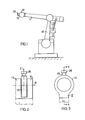
- Fig. 1 eine Seitenansicht eines schematisch dargestellten Industrieroboters mit einem Handgelenk gemäss der Erfindung,
- Fig. 2 das Handgelenk in schematischer Darstellung von unten gesehen,
- Fig. 3 das Handgelenk in schematischer Darstellung von der Seite gesehen,
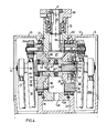
- Fig. 4 in vergrösserter Darstellung einen Schnitt längs der Linie 4-4 in Fig. 3,
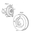
- Fig. 5 eine perpektivische Darstellung des zweiten Bauteils der zweiten scheibenförmigen Einheit,
- Fig. 6 eine perspektivische Darstellung des ersten Bauteils der zweiten scheibenförmigen Einheit.
- 1 is a side view of a schematically illustrated industrial robot with a wrist according to the invention,
- 2 seen the wrist in a schematic representation from below,
- 3 the wrist seen in a schematic representation from the side,
- 4 is an enlarged view of a section along the line 4-4 in Fig. 3,
- 5 is a perspective view of the second component of the second disc-shaped unit,
- Fig. 6 is a perspective view of the first component of the second disc-shaped unit.
Die in Fig. 1 gezeigte Vorrichtung hat zwei verstellbare Arme 10, 11, deren Lagen mittels in bekannter Weise programmierbarer elektrischer Motoren eingestellt werden können.The device shown in Fig. 1 has two
Am Ende des freien Armes 11 (Unterarm) befindet sich ein fest angeordnetes Gehäuse 12, in welchem die die Erfindung kennzeichnenden Teile des Handgelenks untergebracht sind. Das Gehäuse ist in zwei Hälften 13, 14 unterteilt, zwischen denen ein Gehäuse 15 angeordnet ist, welches um eine Achse X drehbar ist und eine hülsenartige Form hat, deren Längsachse Z radial zur Drehachse X orientiert ist.At the end of the free arm 11 (forearm) there is a
Eine erste scheibenförmige Einheit 16 (Fig. 4) trägt das Gehäuse 15 und ist um die quer verlaufende Achse X drehbar, und zwar in dem gezeigten Ausführungsbeispiel durch eine Antriebsvorrichtung, die aus zwei Antriebsstangen 17 und 18 besteht.A first disk-shaped unit 16 (FIG. 4) carries the
Eine zweite scheibenförmige Einheit 19 ist ebenfalls um die quer verlaufende Achse X drehbar, und zwar durch eine Antriebsvorrichtung, die aus zwei Antriebsstangen 20 und fOa besteht.A second disc-
Die beiden scheibenförmigen Einheiten sind drehbar in der Wand 23 beziehungsweise 24 des Gehäuses mittels Kugellager 21 beziehungsweise 22 gelagert und unabhängig voneinander drehbar.The two disk-shaped units are rotatably mounted in the
Eine Welle 25 ist in dem Gehäuse 15 drehbar um die zur X-Achse radial verlaufende Z-Achse angeordnet. An ihrem äusseren Ende ist sie mit einer Befestigungsvorrichtung 26 für einen Werkzeughalter oder eine ähnliche Arbeitseinrichtung versehen. Auf dem innen gelegenen Ende der Welle ist ein angetriebenes Kegelzahnrad 27 aufgesetzt, dessen Zähne 28 im Eingriff mit den Zähnen 29 des antreibenden Kegelzahnrades 30 stehen.A shaft 25 is arranged in the
Das Kegelzahnrad 30 ist ein zweiter Bestandteil der zweiten scheibenförmigen Einheit 19, zu der auch ein ringförmiger erster Bestandteil 31 gehört.The
Wie Fig. 5 zeigt, hat das Kegelzahnrad 30 eine zylindrische Führungsfläche 32 und zwei Klauen 33, die in axialer Richtung aus der hinteren Stirnfläche herausragen. Das erste Bauteil 31 hat eine zylindrische Ausdrehung 34, welche die Führungsfläche 32 des Kegelzahnrades aufnimmt. An der Innenseite des ringförmigen ersten Bauteils 31 ist eine Schulter 35vorhanden, die mitAusnehmungen 35A versehen ist zur Aufnahme und Anlage der Klauen 33 des Handgelenkes 30. Auf diese Weise sind das erste und zweite Bauteil der zweiten scheibenförmigen Einheit 19, also das ringförmige Bauteil 31 und das Kegelzahnrad 30, derart miteinander verbunden, dass das Kegelzahnrad in axialer Richtung in verschiedenen Stellungen relativ zum ringförmigen Bauteil 31 positioniert werden kann, während das letztgenannten Bauteil durch die Kugellager 22 in einer axial festen Lage gehalten wird. Beide Bauteile 30, 31 sind durch die Klauen 33, die in axialer Richtung in den Ausnehmungen 35A verschiebbar sind, derart miteinander verbunden, dass eine gegenseitige Drehung der Bauteile nicht möglich ist.5 shows, the
Die erste Einheit 16 hat im wesentlichen die Form einer Scheibe 36, die mittels Schrauben 37 an der Wand 38 des Gehäuses 15 befestigt ist. Der innere Ring 21 A des Lagers 21 und ein Distanzring 39 bilden ein Distanzglied und gleichzeitig ein kraftübertragendes Glied zwischen der Scheibe 36 und dem Gehäuse 15, die zusammen die erste Einheit 16 bilden.The first unit 16 has essentially the shape of a disk 36 which is fastened to the
In der gezeigten Ausführungsform ist das Kegelzahnrad 30 durch eine Hülse 40 verlängert, mit der das Kegelzahnrad nicht drehbar mittels einer Ringmutter 41 verbunden ist. Alternativ können Kegelzahnrad 30 und Hülse 40 als ein integrales Bauteil hergestellt sein.In the embodiment shown, the
Das von dem Kegelzahnrad abgewandte Ende der Hülse 40 ist mittels eines Nadellagers 42 drehbar in der ersten Einheit 16 gelagert. Dadurch wird eine genaue Zentrierung des Kegelzahnrades 30 erreicht, da das Kegelzahnrad mit seinen Zähnen 29 von zwei Lagern 42 und 22 getragen wird, die sich in einem relativ weiten Abstand voneinander befinden.The end of the
Um das Kegelzahnrad 30 in der gewünschten axialen Lage halten zu können und um zwecks Justierung des Spiels zwischen den Kegelzahnrädern 30 und 27 die genannte Lage schnell und einfach ändern zu können, ist eine Justierschraube 43 vorhanden, die sich durch ein zentrales Loch in der ersten Einheit 16 erstreckt und durch die Bohrung in der Hülse 40 geführt wird. Die Schraube 43 hat einen Kopf 44, der über ein axiales Nadellager 45 drehbar gegen die erste Einheit anliegt. Der Schraubenkopf hat einen Schlitz 46, so dass die Schraube mittels eines Schraubenziehers oder eines anderen Werkzeuges bequem gedreht werden kann.In order to be able to hold the
Die Schraube 43 wird normalerweise im Verhältnis zur Hülse 40 festgehalten, und zwar durch ein Paar Festsetzschrauben 47 die mittels eines Schraubenziehers durch eine Öffnung 48 in der Wand 49 des Gehäuses 15 leicht zugänglich sind.The
Der Endabschnitt der Schraube 43 ist mit Gewinde 50 versehen, welches mit einem entsprechenden Gewinde 51 an der Innenseite der Hülse 40 zusammenwirkt.The end portion of the
Wenn die Festsetzschrauben 47 gelöst werden, kann die Justierschraube 43 mittels eines Schraubenziehers gedreht werden. Das Kegelzahnrad 30 mit der Hülse 40 der zweiten Einheit werden dabei gegen Drehung blockiert durch die zweite scheibenförmige Einheit 19 und die Verbindungsstangen 20, 20a, während gleichzeitig dem Kegelzahnrad 30 und der Hülse 40 über die Gewinde 50, 51 eine axiale Verschiebung aufgezwungen wird bis das gewünschte Spiel zwischen den Kegelzahnrädern erreicht worden ist. Dann werden die Schrauben 47 wieder festgesetzt. Eine Neujustierung der axialen Lage des Kegelzahnrades 30 kann so schnell und in zuverlässiger Weise selbst durch weniger qualifiziertes Personal durchgeführt werden.When the
Um das axiale Spiel der Lager 21, 22 aufzunehmen, ist ein unter Spannung stehender federnder Dichtungsring 52 zwischen einer auf der Schraube 43 sitzenden Mutter 53 und einem Zwischenring 54 angeordnet, wobei der Zwischenring 54 gegen eine Schulter 35 des ringförmigen Bauteils 31 anliegt.In order to absorb the axial play of the
Zwischen dem Gehäuse 15 und der zweiten Einheit 19 ist ein Kugellager 55 angeordnet, welches zusammen mit dem Lager 22 die Montage auf der einen Seite Gehäuses 15 bildet, während das Gehäuse auf der anderen Seite von dem Lager 21 getragen wird.A ball bearing 55 is arranged between the
Claims (2)
Applications Claiming Priority (2)
| Application Number | Priority Date | Filing Date | Title |
|---|---|---|---|
| SE8403043A SE454251B (en) | 1984-06-06 | 1984-06-06 | Robot wrist with device for adjusting gears |
| SE8403043 | 1984-06-06 |
Publications (2)
| Publication Number | Publication Date |
|---|---|
| EP0164112A1 EP0164112A1 (en) | 1985-12-11 |
| EP0164112B1 true EP0164112B1 (en) | 1987-09-16 |
Family
ID=20356157
Family Applications (1)
| Application Number | Title | Priority Date | Filing Date |
|---|---|---|---|
| EP19850106977 Expired EP0164112B1 (en) | 1984-06-06 | 1985-06-05 | A wrist mechanism for an industrial robot |
Country Status (3)
| Country | Link |
|---|---|
| EP (1) | EP0164112B1 (en) |
| DE (1) | DE3560617D1 (en) |
| SE (1) | SE454251B (en) |
Cited By (1)
| Publication number | Priority date | Publication date | Assignee | Title |
|---|---|---|---|---|
| CN110328767A (en) * | 2019-07-01 | 2019-10-15 | 深圳市华星光电技术有限公司 | A kind of offal timber clamp device |
Families Citing this family (6)
| Publication number | Priority date | Publication date | Assignee | Title |
|---|---|---|---|---|
| FR2610562B1 (en) * | 1987-02-05 | 1993-12-03 | Euritech | INTERVENTION PLIERS ARTICULATED WITH FIVE DEGREES OF FREEDOM |
| SE462524B (en) * | 1987-05-20 | 1990-07-09 | Asea Ab | DEVICE FOR ADJUSTING GAMES IN A WRAPPING PART OF AN INDUSTRIAL ROBOT |
| CN105276137A (en) * | 2014-06-11 | 2016-01-27 | 桂林航天工业学院 | Dual-axle seat deadweight anti-backlash numerical control displacement machine |
| CN105945991B (en) * | 2016-05-28 | 2018-01-02 | 陈赛飞 | It is a kind of to perform the swingable robot in end |
| EP3636391B1 (en) * | 2018-10-11 | 2022-12-28 | BSH Hausgeräte GmbH | Joint and household assistant |
| CN110625107A (en) * | 2019-11-05 | 2019-12-31 | 湖北华远装备制造股份有限公司 | Ladle long nozzle manipulator |
Family Cites Families (3)
| Publication number | Priority date | Publication date | Assignee | Title |
|---|---|---|---|---|
| GB249340A (en) * | 1925-04-17 | 1926-03-25 | John Pierce | Improvements relating to bevel gearing |
| JPS58160091A (en) * | 1982-03-12 | 1983-09-22 | 富士通フアナツク株式会社 | Regulating mechanism of backlash of robot |
| SE435030B (en) * | 1983-01-25 | 1984-09-03 | Asea Ab | Hand link for a robot |
-
1984
- 1984-06-06 SE SE8403043A patent/SE454251B/en not_active IP Right Cessation
-
1985
- 1985-06-05 DE DE8585106977T patent/DE3560617D1/en not_active Expired
- 1985-06-05 EP EP19850106977 patent/EP0164112B1/en not_active Expired
Cited By (2)
| Publication number | Priority date | Publication date | Assignee | Title |
|---|---|---|---|---|
| CN110328767A (en) * | 2019-07-01 | 2019-10-15 | 深圳市华星光电技术有限公司 | A kind of offal timber clamp device |
| CN110328767B (en) * | 2019-07-01 | 2021-07-23 | Tcl华星光电技术有限公司 | Device is got to incomplete material clamp |
Also Published As
| Publication number | Publication date |
|---|---|
| SE454251B (en) | 1988-04-18 |
| DE3560617D1 (en) | 1987-10-22 |
| SE8403043D0 (en) | 1984-06-06 |
| EP0164112A1 (en) | 1985-12-11 |
| SE8403043L (en) | 1985-12-07 |
Similar Documents
| Publication | Publication Date | Title |
|---|---|---|
| EP0142611B1 (en) | Drill tool for manufacturing reliefs in prefabricated bores | |
| CH656335A5 (en) | DRILLING TOOL. | |
| DE3531160A1 (en) | TOOL CHANGER FOR A MACHINE TOOL | |
| DE3906510C2 (en) | ||
| EP0109666A1 (en) | Hand tool with depth adjuster | |
| DE3929802C1 (en) | ||
| DE3613987C2 (en) | ||
| DE3719064A1 (en) | ROBOT WRIST | |
| DE4239559C2 (en) | Hand tool with a blocking device for blocking the tool spindle when changing tools | |
| EP0164112B1 (en) | A wrist mechanism for an industrial robot | |
| EP0410104B1 (en) | Chip making machining tool | |
| DE2511081A1 (en) | SLOTTING OR PUNCHING MACHINE | |
| DE8308464U1 (en) | Protective cover for a hand-held machine tool | |
| DE3605913C2 (en) | ||
| EP0684099A1 (en) | Combination tool | |
| DE1491029A1 (en) | Dental handpiece | |
| DE1297320B (en) | Device for cutting off a pipe at its end | |
| DE3814189C2 (en) | ||
| CH660992A5 (en) | DEVICE FOR THE COOLANT SUPPLY TO ROTATING CUTTING TOOLS PROVIDED WITH COOLANT CHANNELS FOR THE CUTTING METAL WORKING, IN PARTICULAR DRILLING TOOLS. | |
| CH652951A5 (en) | BORING TOOL AND FLATCHING TOOL. | |
| DE3432942C2 (en) | ||
| DE2601388A1 (en) | Reamed bolt for machined plates - has two rotating eccentrics and sleeves to adapt to position of through holes | |
| DE2150558C3 (en) | Drill head | |
| DE2501433C3 (en) | Device for releasably attaching a blade unit to the frame of a motorized lawn mower | |
| DE3116389C2 (en) | Self-propelled flame cutting machine for bevel cuts |
Legal Events
| Date | Code | Title | Description |
|---|---|---|---|
| PUAI | Public reference made under article 153(3) epc to a published international application that has entered the european phase |
Free format text: ORIGINAL CODE: 0009012 |
|
| AK | Designated contracting states |
Designated state(s): DE FR GB IT |
|
| 17P | Request for examination filed |
Effective date: 19860321 |
|
| 17Q | First examination report despatched |
Effective date: 19861106 |
|
| GRAA | (expected) grant |
Free format text: ORIGINAL CODE: 0009210 |
|
| AK | Designated contracting states |
Kind code of ref document: B1 Designated state(s): DE FR GB IT |
|
| REF | Corresponds to: |
Ref document number: 3560617 Country of ref document: DE Date of ref document: 19871022 |
|
| ITF | It: translation for a ep patent filed |
Owner name: JACOBACCI & PERANI S.P.A. |
|
| ET | Fr: translation filed | ||
| PLBE | No opposition filed within time limit |
Free format text: ORIGINAL CODE: 0009261 |
|
| STAA | Information on the status of an ep patent application or granted ep patent |
Free format text: STATUS: NO OPPOSITION FILED WITHIN TIME LIMIT |
|
| 26N | No opposition filed | ||
| ITTA | It: last paid annual fee | ||
| PGFP | Annual fee paid to national office [announced via postgrant information from national office to epo] |
Ref country code: GB Payment date: 19990602 Year of fee payment: 15 |
|
| PGFP | Annual fee paid to national office [announced via postgrant information from national office to epo] |
Ref country code: DE Payment date: 19990607 Year of fee payment: 15 |
|
| PGFP | Annual fee paid to national office [announced via postgrant information from national office to epo] |
Ref country code: FR Payment date: 19990610 Year of fee payment: 15 |
|
| PG25 | Lapsed in a contracting state [announced via postgrant information from national office to epo] |
Ref country code: GB Free format text: LAPSE BECAUSE OF NON-PAYMENT OF DUE FEES Effective date: 20000605 |
|
| GBPC | Gb: european patent ceased through non-payment of renewal fee |
Effective date: 20000605 |
|
| PG25 | Lapsed in a contracting state [announced via postgrant information from national office to epo] |
Ref country code: FR Free format text: LAPSE BECAUSE OF NON-PAYMENT OF DUE FEES Effective date: 20010228 |
|
| REG | Reference to a national code |
Ref country code: FR Ref legal event code: ST |
|
| PG25 | Lapsed in a contracting state [announced via postgrant information from national office to epo] |
Ref country code: DE Free format text: LAPSE BECAUSE OF NON-PAYMENT OF DUE FEES Effective date: 20010403 |