EP0894525B1 - Hoisting apparatus for an aggregate, in particular a submersible motorised stirrer in a closed vessel - Google Patents
Hoisting apparatus for an aggregate, in particular a submersible motorised stirrer in a closed vessel Download PDFInfo
- Publication number
- EP0894525B1 EP0894525B1 EP98113874A EP98113874A EP0894525B1 EP 0894525 B1 EP0894525 B1 EP 0894525B1 EP 98113874 A EP98113874 A EP 98113874A EP 98113874 A EP98113874 A EP 98113874A EP 0894525 B1 EP0894525 B1 EP 0894525B1
- Authority
- EP
- European Patent Office
- Prior art keywords
- shaft
- vessel
- rope drum
- hoisting apparatus
- assembly
- Prior art date
- Legal status (The legal status is an assumption and is not a legal conclusion. Google has not performed a legal analysis and makes no representation as to the accuracy of the status listed.)
- Expired - Lifetime
Links
Images


Classifications
-
- B—PERFORMING OPERATIONS; TRANSPORTING
- B66—HOISTING; LIFTING; HAULING
- B66D—CAPSTANS; WINCHES; TACKLES, e.g. PULLEY BLOCKS; HOISTS
- B66D1/00—Rope, cable, or chain winding mechanisms; Capstans
- B66D1/60—Rope, cable, or chain winding mechanisms; Capstans adapted for special purposes
-
- B—PERFORMING OPERATIONS; TRANSPORTING
- B01—PHYSICAL OR CHEMICAL PROCESSES OR APPARATUS IN GENERAL
- B01F—MIXING, e.g. DISSOLVING, EMULSIFYING OR DISPERSING
- B01F27/00—Mixers with rotary stirring devices in fixed receptacles; Kneaders
- B01F27/25—Mixers with both stirrer and drive unit submerged in the material being mixed
- B01F27/251—Vertical beam constructions therefor
-
- C—CHEMISTRY; METALLURGY
- C12—BIOCHEMISTRY; BEER; SPIRITS; WINE; VINEGAR; MICROBIOLOGY; ENZYMOLOGY; MUTATION OR GENETIC ENGINEERING
- C12M—APPARATUS FOR ENZYMOLOGY OR MICROBIOLOGY; APPARATUS FOR CULTURING MICROORGANISMS FOR PRODUCING BIOMASS, FOR GROWING CELLS OR FOR OBTAINING FERMENTATION OR METABOLIC PRODUCTS, i.e. BIOREACTORS OR FERMENTERS
- C12M21/00—Bioreactors or fermenters specially adapted for specific uses
- C12M21/04—Bioreactors or fermenters specially adapted for specific uses for producing gas, e.g. biogas
-
- C—CHEMISTRY; METALLURGY
- C12—BIOCHEMISTRY; BEER; SPIRITS; WINE; VINEGAR; MICROBIOLOGY; ENZYMOLOGY; MUTATION OR GENETIC ENGINEERING
- C12M—APPARATUS FOR ENZYMOLOGY OR MICROBIOLOGY; APPARATUS FOR CULTURING MICROORGANISMS FOR PRODUCING BIOMASS, FOR GROWING CELLS OR FOR OBTAINING FERMENTATION OR METABOLIC PRODUCTS, i.e. BIOREACTORS OR FERMENTERS
- C12M27/00—Means for mixing, agitating or circulating fluids in the vessel
- C12M27/02—Stirrer or mobile mixing elements
- C12M27/06—Stirrer or mobile mixing elements with horizontal or inclined stirrer shaft or axis
-
- B—PERFORMING OPERATIONS; TRANSPORTING
- B01—PHYSICAL OR CHEMICAL PROCESSES OR APPARATUS IN GENERAL
- B01F—MIXING, e.g. DISSOLVING, EMULSIFYING OR DISPERSING
- B01F35/00—Accessories for mixers; Auxiliary operations or auxiliary devices; Parts or details of general application
- B01F35/30—Driving arrangements; Transmissions; Couplings; Brakes
- B01F2035/35—Use of other general mechanical engineering elements in mixing devices
- B01F2035/351—Sealings
-
- Y—GENERAL TAGGING OF NEW TECHNOLOGICAL DEVELOPMENTS; GENERAL TAGGING OF CROSS-SECTIONAL TECHNOLOGIES SPANNING OVER SEVERAL SECTIONS OF THE IPC; TECHNICAL SUBJECTS COVERED BY FORMER USPC CROSS-REFERENCE ART COLLECTIONS [XRACs] AND DIGESTS
- Y02—TECHNOLOGIES OR APPLICATIONS FOR MITIGATION OR ADAPTATION AGAINST CLIMATE CHANGE
- Y02E—REDUCTION OF GREENHOUSE GAS [GHG] EMISSIONS, RELATED TO ENERGY GENERATION, TRANSMISSION OR DISTRIBUTION
- Y02E50/00—Technologies for the production of fuel of non-fossil origin
- Y02E50/30—Fuel from waste, e.g. synthetic alcohol or diesel
Definitions
- the invention relates to a lifting device for units, in particular a Submersible mixer, in a sealed container, especially in one Fermentation tank of a biogas plant according to the preamble of the claim 1.
- a fermentation process takes place in biogas plants, in which organic Fabrics such as B. grass, manure, liquid manure, sewage sludge, straw and the like be gassed. These gases collect in an upper area of the fermenter tank and can be used directly for power generation be, e.g. B. as heating gas for power generation in downstream internal combustion engines with electrical generators.
- the fermentation process takes place in a fermenter tank instead, in which the organic matter is mixed with liquid are added and the fermentation or gasification process under aerobic or anaerobic conditions by microorganisms such as z. B. yeasts, bacteria, etc. is carried out.
- a submersible mixer is known that by means of a winch of a lifting device along an assembly carrier is movable.
- a generic lifting device known from DE 41 20 987 A1 each comprises a unit carrier arranged vertically in the container, the is stored in upper and lower bearings and on which the unit is adjustable in height is held.
- the lifting device each has a height adjustment device as a winch for the unit, one with the Unit carrier firmly connected rope drum with horizontal rope drum shaft, one connected to the unit on the one hand and on the other hand rope that can be wound onto the rope drum, a rope drum drive and a Actuating device for the cable drum drive arranged outside the container includes.
- the rope drum and crank are used as actuation devices above an upper container wall and thus outside of the container arranged an aggregate carrier.
- the upper container wall is the rope starting from the rope drum inside of the hollow assembly carrier in the liquid area down.
- the rope exits the assembly carrier through an outlet opening out and is deflected outside of the Subrack up to an upper area of the subframe led, the gas tightness through the lying above the outlet opening Liquid is obtained.
- There the rope is then over further pulleys again deflected and down to a submersible mixer guided.
- a major disadvantage of such a structure is that the outlet opening of the rope at the lower end of the beam, especially with long-fiber Add solids and thereby block the rope guide pulley can, so that a height adjustment of the unit is no longer possible. Also with such a construction is a long cable guide with several Deflection pulleys necessary.
- a lifting device for a biogas plant is from the DE 195 17 901 C1 known. Again, one is on outside the container provided a cable drum arranged from the assembly the rope is fed through a gland seal into the container is.
- the stuffing box is constructed in two parts from threaded pipes and on a turntable arranged to pivot the subframe to enable its longitudinal axis, also rotates via slide rings. Overall, this is a complicated and time-consuming process Rope implementation and storage of the subframe in the area a container ceiling. Problems arise in particular because that the steel cable used frayed over time and thereby a sharp cutting edge that forms as part of the up and down movement the stuffing box is damaged. The stuffing box then forms a leak that the biogas can escape into the environment. This increases due to the maintenance work to be carried out significantly increases the repair costs.
- the object of the invention is therefore to provide a lifting device for units, especially a submersible mixer in a sealed container, in particular to create in a fermenter tank of a biogas plant that a reliable, easy to install and maintain operating and tight structure with simple rope routing.
- the rope drum is within the upper area of the Container arranged so that no gas-tight cable passage through a Container wall is required.
- the one located outside the container Actuator with the by means of a tight implementation connected by a drum wall guided cable drum drive.
- the cable drum is actuated with the actuating device simple way from the outside of the container, the switched on there Energy supply or applied kinetic energy via the cable drum drive is transferred to the cable drum.
- the application according to the invention is preferred in biogas plants in Connection used with submersible mixers.
- the arrangement can also advantageous for other, similar applications, possibly with others Aggregates such as Submersible pumps are used.
- the container comprises a dome as e.g. from the patent application P 197 14 342.3-41 is known.
- the cathedral is on an upper one Container wall placed tightly, with an upper area of the assembly carrier, on which the rope drum is arranged, protrudes into the cathedral.
- This cathedral has at least one gas-tight lockable dome opening through which through access to one by means of the height adjustment device possible to move the container interior into the interior of the dome is. So both simple and extensive repair and / or need Maintenance work by the installer no longer in the container interior to be done, but can be more convenient and easier be carried out from the outside through the dome opening. For example the fermentation process then needs a fermenter and / or maintenance work is no longer uneconomically reduced to become, but can run continuously. the whole complex is therefore more economical to operate.
- the dome can have any conceivable shape, e.g. B. a round or have angular floor plan or cylindrical or box-shaped his.
- the dimensions of the cathedral are also depending on the application arbitrary, so z. B. man-high executable.
- a window can also be provided in a dome wall so that the operations can be observed from the inside without opening the cathedral.
- the lifting device is a rotary adjustment device for the assembly carrier with a rotary drive with which it can be rotated about its vertical longitudinal axis is adjustable and fixable in a certain rotational position, wherein the unit is kept rotating on the unit carrier.
- a such rotation of the assembly carrier about its longitudinal axis is due the inner rope drum is easily possible, since none complicated, gas-tight cable entry through a container wall more is required.
- the unit With such a rotary adjustment of the subframe the unit can also be positioned vertically using the height adjustment device also in a perpendicular to the longitudinal axis of the subframe horizontal plane can be pivoted. So there is always one correct positioning of the unit guaranteed.
- the rotary drive of the rotary adjustment device is preferred in the upper area of the subframe within the container Electric motor that prefers a motor rotation over a Transmits gear assembly to the subframe and the outside of the container via a control unit as an actuating device, preferably via a counter-clockwise / clockwise rotation button, controllable and via a tight cable entry through a container wall, preferably a dome wall is connected to the control unit.
- a control unit as an actuating device, preferably via a counter-clockwise / clockwise rotation button, controllable and via a tight cable entry through a container wall, preferably a dome wall is connected to the control unit.
- a rotary drive is easy to handle.
- a commercially available, gas-tight can be used as the electric motor encapsulated and explosion-proof electric motor can be used, which guarantees high operational reliability.
- Next is a tight cable entry preferably the one to be provided anyway in a container wall Cable entry used for the unit drive.
- control unit is preferably used both for Actuation of the unit drive as well as for actuation of the rotary drive.
- the locking in a certain swivel position is through the self-locking gearbox of the electric motor causes.
- a fixed rotary drive shaft Rotary drive of the subframe, preferably as an extension of the subframe, through a dense shaft bushing in generally known and proven embodiments by a container wall, preferred led a cathedral wall.
- a rotary drive is simple and therefore inexpensive to manufacture and less prone to failure.
- an actuator for the rotary drive is a hingedly connected to the outer end of the fixed rotary drive shaft, swiveling control lever, which is in a certain rotational position via a locking device, preferably a fork catch, on a container wall, preferably an upper dome wall, can be fixed.
- a locking device preferably a fork catch
- a container wall preferably an upper dome wall
- the locking lever is fixed by the locking device the subframe in a certain swivel position.
- swiveling lever can also a rigid connection of the control lever to the outer end of the stationary Rotary drive shaft may be provided.
- the fixation takes place z. B. about a locking pin, the lever z. B. at a fixed, assigned Setting disk.
- stops for limiting a rotary adjustment the unit carrier on the unit carrier and / or a container wall preferably arranged a cathedral wall. Allow such stops a defined pivoting of the unit in a horizontal plane, these attacks in particular prevent an aggregate, if the Unit carrier is arranged near a container wall, on the inner wall of the container strikes. Likewise can be defined by such Avoid swiveling within a certain swiveling range be that the unit cable due to inattentive handling is wrapped around the subframe several times, which impair operation can.
- the cable drum drive comprises one on the cable drum and thus mounted within the container electric motor, the from outside the container via a control unit as an actuating device, preferably via a counterclockwise / clockwise rotation button, controllable and over a sealed cable duct through a container wall, preferred a dome wall, is connected to the control unit.
- a control unit as an actuating device, preferably via a counterclockwise / clockwise rotation button, controllable and over a sealed cable duct through a container wall, preferred a dome wall, is connected to the control unit.
- an electric motor can also be a gas-tight, explosion-proof, conventional one Electric motor can be used.
- the control unit is preferably used both to actuate the unit drive as well as for actuating the electric motor of the cable drum drive.
- a reliable lifting device can thus be realized with both a rotary adjustment of the subframe and a height adjustment of the unit from outside the container is possible.
- the cable drum drive includes Means for deflecting the direction of movement, the deflection in the axis of rotation of the subframe.
- the means of redirection the direction of motion transmission are on the one hand with the stationary Shaft and on the other hand connected to the cable drum shaft. With a lifting device constructed in this way is therefore possible both a height adjustment of the aggregate along the aggregate as well make a rotation adjustment of the subframe itself. It is only an easy to manufacture with known means and bearings, sealed shaft bushing for the stationary shaft through a container wall provided.
- the means for deflecting the direction of movement comprise a propeller shaft, the at least one joint in the axis of rotation of the subframe and their shaft parts on both sides are the fixed shaft and the cable drum shaft.
- a propeller shaft As cardan shafts z. B. commercially available and inexpensive single universal joints or double universal joints used a rotational movement from the stationary Transfer the shaft to the cable drum shaft and thus the cable drum.
- Rope drum shaft can also serve a rigid rope drum axis here interacts with a shaft part of the rope drum and just the rope drum shaft forms.
- the swivel range is determined by the Spherical bearing geometry specified. So here is a simple way A PTO shaft ensures that the unit is lifted both adjusted in height and pivoted in a horizontal plane can be.
- the PTO shaft is above the stationary shaft simple way z. B. stored in a gas-tight socket in the container wall.
- the socket preferably also serves as a cardan shaft guide.
- the cardan shaft can also additionally in the area of the shaft joint be guided in a spherical plain bearing.
- the means for deflecting the direction of movement comprise a profile ring, preferably a straight toothed or bevel gear toothed ring, which is freely rotatable on the assembly carrier is and that with an assigned engagement profile on the stationary Shaft and the cable drum shaft is engaged.
- a profile ring preferably a free across the longitudinal axis of an assembly carrier on this rotatable ring gear can be used, which has a marginal, straight-toothed Toothed ring on the one hand with a straight toothed, preferred End tooth profile of the fixed shaft of the cable drum drive and on the other hand with a straight toothed, preferably end gear the cable drum shaft is engaged.
- the two waves are at one such a construction is preferred with regard to the longitudinal axis of the assembly carrier at the same height and have the same gears, so that an approximately elongated structure of the means for deflecting the direction of movement results.
- the profile ring on a in the longitudinal direction of the assembly carrier seen the upper and lower edge of the profile ring a circumferential bevel gear profile exhibit.
- the upper bevel gear profile of the profile gear a preferably bevel gear on the end of the fixed shaft of the cable drum drive, while also with the lower bevel gear part of the profile ring preferably combs the end bevel gear of the cable drum shaft.
- the transmission of motion works here exactly as with the previously described Ring gear construction, only that the two prefer the same bevel gear profiles provided shafts of the cable drum drive here for one compact structure are preferably arranged one above the other.
- the actuator is a crank which with the stationary shaft of the cable drum drive is connected.
- Such conventional crank can be easily operated by an operator with the Be operated by hand, depending on the desired height adjustment direction the crank turned to the left or to the right becomes.
- the geometry of the crank is the one to be used accordingly Adjusted force.
- At least one upper stop is on the assembly carrier for the defined height adjustment of the unit with the cable drum drive arranged. Such an upper stop prevents an uncontrolled Pulling up the unit, e.g. B. too high in the interior of the cathedral.
- the assembly carrier with an upper end of the carrier or a rotary drive shaft possibly connected to the upper end of the carrier in an upper container wall, preferably an upper dome wall and with a lower end of the support in a lower container wall. Due to the rope drum arranged inside, a stable and especially easy to carry out storage, especially of the upper one Realize the beam end in a container wall, where no consideration is given to a gas-tight cable duct can be used in this area got to. As a seal z. B. a conventional gas-tight bush seal be used.
- the assembly carrier is in two parts from a lower Support part and an upper support part with a dividing line in the area below the fixed connection of the cable drum to the assembly carrier, the lower support part is a profile support and the upper support part at least in the area of a container wall bushing, preferred a dome wall bushing, which forms the rotary drive shaft of the rotary drive, which are releasably connected to each other if necessary.
- a division of the subframe in the upper and lower support part can at Assembly a simple and quick adaptation to the prevailing Installation conditions can be achieved. So it is z. B. possible first insert the lower carrier into the container, place it on the cut to the correct length and then together with the upper support part z. B. put on the cathedral wall.
- the upper and lower support part can are welded at their interface or releasably together be connected to e.g. B. to enable quick disassembly.
- the assembly carrier is at least partially as a profile carrier designed with an open profile cross-section.
- a profile beam makes it easy to ensure that the unit is in a rotation of the assembly carrier rotates about its longitudinal axis.
- the profile carrier does not have to be hollow to z.
- a rope for one to record gas-tight cable feedthrough as is the case in the prior art the case is, it can be designed with a simple, open profile cross section be the easier to manufacture and therefore cheaper than a closed one Profile cross section is.
- FIG. 1 is a first embodiment of a lifting device 1 for a Submersible mixer 2 in a sealed fermenter tank 3 of a biogas plant shown.
- An upper container wall 4 comprises an opening 5, around which a dome 9 is placed tightly on the upper container wall 4.
- the fermenter container 3 can completely or at least partially in the Be sunk.
- the dome 9 can have thermal insulation on the outside, as shown in dashed lines in Fig. 1, and also a control window 15 have.
- An assembly carrier 7 is arranged vertically in the fermenter container 3.
- the Unit carrier 7 is with a lower carrier end 8 in a lower bearing 10 rotatably mounted on a lower container wall 6.
- An upper beam end 11 of the assembly carrier 7 projects through the opening 5 into an interior 12 of the cathedral 9.
- the upper end of the carrier 11 comprises at the end as an extension of the assembly carrier 7 a stationary rotary drive shaft 13 of a rotary drive 14 this rotary drive 14 of the lifting device 1 is the unit carrier 7 the vertical longitudinal axis 16 rotatable in a certain rotational position adjustable and definable.
- This is the fixed rotary drive shaft 13 through a gas-tight bushing 17 as a tight shaft bushing through a upper cathedral wall 18 out.
- pivotable Setting lever 20 is provided as an actuating device. This lever 20 is via a fork catch 21 as a locking device on the upper dome wall 18 can be fixed in a certain rotational position of the assembly carrier 7.
- a cable drum 24 with a horizontal cable drum shaft 26 via a Console 25 is firmly connected to the assembly carrier 7.
- One on the rope drum 24 windable rope 27 is with a free rope end 28 connected to the submersible mixer 2 for its height adjustment.
- the Rope length is chosen so that the submersible mixer 2 is maximum can be lowered just before the lower container wall 6.
- a rope drum drive 30 is also provided for height adjustment an electric motor 31 attached to the cable drum 24.
- This Electric motor 31 is from outside dome 9 via a control unit 32 as an actuator, which is shown only schematically in FIG. 1 as a box is drawn, preferably via a counterclockwise / clockwise rotation button, controllable.
- the control unit 32 is through a sealed cable duct 33 the upper dome wall 18 connected to the electric motor 31.
- About the Control unit 32 is also the drive motor of the submersible mixer 2 controllable, which is not shown here.
- the cable 34 is as can be seen from Fig. 1, performed in a loop to a Join the pivoting of the assembly carrier 7 about its longitudinal axis 17 to be able to.
- the Electric motor 31 moves the cable drum 24 and thus the cable 27 depending on set running direction so that the submersible mixer 2 over a conventional roller bearing 22 along the assembly carrier 7 either down towards the lower container wall 6 or towards the dome 9 is proceeded.
- the longitudinal axis 16 moves the adjusting lever 20 out of the fork catch 21, pivoted into a desired stirrer pivot position and then back into an offset fork latch assigned to the swivel position engaged.
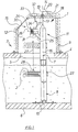
- FIG. 2 shows a lifting device 1, which is an alternative to that in the Fig. 1 illustrated embodiment with a cable drum drive 36 a drive shaft 37 shows.
- the same parts in Figs. 1 and 2 are each designated with the same reference numerals.
- Fig. 2 is a fixed shaft 38 of the propeller shaft 37 of the cable drum drive 36 through a gas-tight bushing as a tight shaft bushing 39 passed through a side dome wall 40.
- the joint 41 of the drive shaft 37 serves as a means for redirecting the direction of motion transmission, the deflection in the axis of rotation 16 of the assembly carrier 7 he follows.
- the hinge 41 is, for. B. a single shaft joint in a spherical plain bearing 42 is guided at the upper end 11 of the support, whereby the joint 41 of the propeller shaft 37 opposite to the fixed shaft 38 of the Drive shaft 37 connects a cable drum shaft 43 of the drive shaft 37.
- This cable drum shaft 43 transmits rotation to the cable drum 24 connected.
- a crank 45 is used as an actuating device for actuating the propeller shaft 37 provided with the fixed shaft 38 of the cable drum drive 36 is connected.
- the console 25 at the upper end 11 of the carrier Stop can be used.
- a rotary movement can be done here via crank 45 are transmitted to the cable drum 24 via the cardan shaft 37.
- the submersible mixer 2 can be raised according to the direction of rotation or lowered.
- the cable drum shaft 43 in a plane perpendicular to the vertical longitudinal axis 16 be pivoted relative to the fixed shaft 38, as in the Fig. 3 is shown schematically.
- the maximum pivoting accordingly Arrow 44 of the submersible mixer 2 is shown in FIG. 3 drawn in dashed lines, each in the area of the spherical bearing 42
- Two stops 46, 47 are provided to the left and right of the joint 41 are the maximum degree of pivoting of the submersible mixer 2 pretend.
- FIG. 4 shows a lifting device 1 in which a further alternative Embodiment of a cable drum drive 49 is shown.
- a stationary shaft 50 is here sealed by a gas-tight bushing 51 Shaft lead through a lateral dome wall 52.
- the stationary Shaft 50 has a spur gear 54 at the end, which with a straight toothed toothed ring 58 of a ring gear 53 of the cable drum drive 49 combs.
- the ring gear 53 is freely rotatable on the assembly carrier 7 arranged and is opposite to the fixed shaft 50 a gear 55, which is connected at the end to a cable drum shaft 56 is arranged.
- Crank 57 is the gear 54 of the fixed shaft 50 Transfer rotary motion to ring gear 53.
- the ring gear 53 transmits then the movement on the gear 55 of the cable drum shaft 56.
- the submersible mixer can either up towards Dom 9 or down towards a lower container wall, which is not shown here is to be moved.
- the adjusting lever 20 pivoted according to the desired adjustment.
- the unit carrier 7 in two parts from a lower Support part and an upper support part with a dividing line in the area below the fixed connection of the cable drum 24 to the assembly carrier 7 be constructed, i.e. the cable drum 24 is preferably on the upper support part firmly connected. This is an optimal adaptation to the prevailing Installation conditions possible.
- FIG. 5 shows a lifting device 1
- a cable drum drive 60 is shown with a bevel gear arrangement.
- a domineering ending a stationary shaft 61 which by means of a bush 68 as a shaft bushing is gastight through a side dome wall 69, includes a bevel gear 62 with an upper bevel gear profile 63 of a bevel gear ring 64 combs.
- the bevel gear ring 64 is also freely rotatable on the assembly carrier 7 arranged and transmitted by means of a crank 65 on the stationary Shaft 61 and the bevel gear 62 transmitted to the bevel gear ring 64 movement on a bevel gear 66 of a cable drum shaft 67.
- the submersible mixer 2 can be adjusted upwards or downwards in height.
- the assembly carrier 7 is pivoted about its longitudinal axis 16 and thus the submersible mixer 2 causes the free, rotatable arrangement of the bevel gear ring 64 on the assembly carrier 7 that the pivoting is not blocked and the movement transmission from the stationary Shaft 61 in each pivot position of the assembly carrier 7 on the cable drum shaft 67 is possible.
- the submersible mixer 2, if it starts from the lowered position in the interior of the cathedral 12 is moved, as shown in dashed lines in FIG. 5, so pivoted be that the submersible mixer through the opening 5 can be moved into the dome interior 12.
- the unit carrier can 7 be formed with different profile cross sections, for. B. as a square tube, as a U-beam and as a T-beam. With such a profile carrier it is ensured that the submersible mixer turns when swiveled the subframe 7 rotates.
Abstract
Description
Die Erfindung betrifft eine Hubvorrichtung für Aggregate, insbesondere ein
Tauchmotorrührgerät, in einem dichten Behälter, insbesondere in einem
Fermenterbehälter einer Biogasanlage nach dem Oberbegriff des Anspruchs
1.The invention relates to a lifting device for units, in particular a
Submersible mixer, in a sealed container, especially in one
Fermentation tank of a biogas plant according to the preamble of the
In Biogasanlagen läuft ein Fermentationsprozeß ab, bei dem organische Stoffe, wie z. B. Gras, Stalldung, Jauche, Klärschlamm, Stroh und dergleichen vergast werden. Diese Gase sammeln sich in einem oberen Fermenterbehälterbereich und können direkt zur Energieerzeugung verwendet werden, z. B. als Heizgas zur Stromerzeugung in nachgeschalteten Brennkraftmaschinen mit Elektrogeneratoren. Der Fermentationsprozeß findet in einem Fermenterbehälter statt, in dem die organischen Stoffe mit Flüssigkeit versetzt werden und der Fermentations- bzw. der Vergasungsprozeß unter aeroben oder anaeroben Bedingungen durch Mikroorganismen, wie z. B. Hefen, Bakterien, etc. durchgeführt wird. Zur Verteilung der organischen Feststoffe in der flüssigen Phase ist ein Tauchmotorrührgerät bekannt, das mittels einer Seilwinde einer Hubvorrichtung entlang eines Aggregatträgers verfahrbar ist.A fermentation process takes place in biogas plants, in which organic Fabrics such as B. grass, manure, liquid manure, sewage sludge, straw and the like be gassed. These gases collect in an upper area of the fermenter tank and can be used directly for power generation be, e.g. B. as heating gas for power generation in downstream internal combustion engines with electrical generators. The fermentation process takes place in a fermenter tank instead, in which the organic matter is mixed with liquid are added and the fermentation or gasification process under aerobic or anaerobic conditions by microorganisms such as z. B. yeasts, bacteria, etc. is carried out. To distribute the organic Solids in the liquid phase, a submersible mixer is known that by means of a winch of a lifting device along an assembly carrier is movable.
Bei bekannten Hubvorrichtungen wird davon ausgegangen, daß die Seiltrommel der Seilwinde außerhalb des Behälters im Bereich oberhalb einer oberen Behälterwand anzuordnen ist. Dies erfordert allerdings eine komplizierte und problembehaftete gasdichte Seildurchführung durch die Behälterwand.In known lifting devices, it is assumed that the cable drum the winch outside the container in the area above one upper container wall is to be arranged. However, this requires a complicated one and problematic gas-tight cable entry through the container wall.
Eine aus der DE 41 20 987 A1 bekannte, gattungsgemäße Hubvorrichtung
umfaßt jeweils einen vertikal im Behälter angeordneten Aggregatträger, der
in oberen und unteren Lagern gelagert ist und an dem das Aggregat höhenverstellbar
gehalten ist. Die Hubvorrichtung weist jeweils eine Höhenverstelleinrichtung
als Seilwinde für das Aggregat auf, die eine mit dem
Aggregatträger fest verbundene Seiltrommel mit horizontaler Seiltrommelwelle,
ein einerseits mit dem Aggregat verbundenes und andererseits
auf die Seiltrommel aufwickelbares Seil, einen Seiltrommelantrieb und eine
außerhalb des Behälters angeordnete Betätigungseinrichtung für den Seiltrommelantrieb
umfaßt.A generic lifting device known from
Auch hier ist die Seiltrommel samt Kurbel als Betätigungseinrichtung oberhalb einer oberen Behälterwand und damit außerhalb des Behälters an einem Aggregatträger angeordnet. Zur gasdichten Seildurchführung durch die obere Behälterwand ist das Seil von der Seiltrommel ausgehend innerhalb des hohlen Aggregatträgers in den Flüssigkeitsbereich nach unten geführt. Dort tritt das Seil durch eine Austrittsöffnung hindurch aus dem Aggregatträger aus und wird über eine Umlenkrolle umgelenkt außerhalb des Aggregaträgers nach oben zu einem oberen Bereich des Aggregatträgers geführt, wobei die Gasdichtheit durch die über der Austrittsöffnung liegende Flüssigkeit erhalten wird. Dort wird das Seil dann über weitere Umlenkrollen wiederum umgelenkt und nach unten zu einem Tauchmotorrührgerät geführt.Here too the rope drum and crank are used as actuation devices above an upper container wall and thus outside of the container arranged an aggregate carrier. For gas-tight cable entry the upper container wall is the rope starting from the rope drum inside of the hollow assembly carrier in the liquid area down. There the rope exits the assembly carrier through an outlet opening out and is deflected outside of the Subrack up to an upper area of the subframe led, the gas tightness through the lying above the outlet opening Liquid is obtained. There the rope is then over further pulleys again deflected and down to a submersible mixer guided.
Ein wesentlicher Nachteil eines derartigen Aufbaus ist, daß sich die Austrittsöffnung des Seils am unteren Trägerende insbesondere mit langfasrigen Feststoffen zusetzen und dadurch die Seilführungsrolle blockieren kann, so daß eine Höhenverstellung des Aggregats nicht mehr möglich ist. Ebenso ist bei einem derartigen Aufbau eine lange Seilführung mit mehreren Umlenkrollen notwendig.A major disadvantage of such a structure is that the outlet opening of the rope at the lower end of the beam, especially with long-fiber Add solids and thereby block the rope guide pulley can, so that a height adjustment of the unit is no longer possible. Also with such a construction is a long cable guide with several Deflection pulleys necessary.
Aus der DE 295 02 974 U1 ist eine Hubvorrichtung für eine Biogasanlage bekannt, bei der die Seiltrommel samt Betätigungseinrichtung ebenfalls außerhalb des Behälterdeckels an einem Aggregatträger angeordnet ist. Zur gasdichten Seildurchführung ist das Seil hier außen an dem Aggregatträger entlang bis in eine flüssigkeitsbefüllte Siphondichtung geführt. Dort wird das Seil über eine erste Umlenkrolle um das innere, mit der Behälterdecke verbundene Siphonrohr nach oben und schließlich über eine zweite Umlenkrolle um das äußere, mit dem Aggregatträger verbundene und nach unten abgeschlossene Siphonrohr nach unten zu einem Tauchmotorrührgerät geführt.DE 295 02 974 U1 describes a lifting device for a biogas plant known in which the cable drum together with the actuating device also is arranged outside of the container lid on an assembly carrier. For gas-tight cable routing, the cable is here on the outside of the assembly carrier led along into a liquid-filled siphon seal. There is the rope over a first pulley around the inner, with the container ceiling connected siphon tube upwards and finally via a second one Deflection roller around the outer, connected to the subframe and behind siphon tube closed at the bottom to a submersible mixer guided.
Eine derartige, in der Regel mit Wasser befüllte Siphondichtung weist den Nachteil auf, daß das Wasser in der Dichtung insbesondere bei höheren Umgebungstemperaturen schnell verdunstet, so daß die Dichtwirkung dann nicht mehr gegeben ist. Bei sehr tiefen Temperaturen kann das Wasser dagegen frieren und damit die Umlenkrollen sowie die Seilführung blockieren. Deshalb ist mit einem derartigen Aufbau eine ständige, aufwendige Kontrolle notwendig. Weiter ist zur Lagerung des oberen Aggregatträgerendes eine zusätzliche Lagerkonsole im Deckelbereich vorzusehen, da aufgrund der Siphondichtung und des durch die Siphondichtung geführten Seils die Lagerung des Aggregatträgers in diesem Bereich nicht stabil durchzuführen ist. Ebenso kann mit einem derartigen Aufbau keine Verschwenkung des Aggregatträgers um dessen Längsachse realisiert werden, sondern lediglich eine Höhenverstellung des Aggregats.Such a siphon seal, usually filled with water, has the Disadvantage that the water in the seal, especially at higher Ambient temperatures evaporate quickly, so that the sealing effect then no longer exists. At very low temperatures, the water can on the other hand, freeze and thus the pulleys and the rope guide To block. Therefore, with such a structure is a constant, complex Control necessary. Next is for storing the upper end of the subframe to provide an additional storage bracket in the lid area, because of the siphon seal and the siphon seal guided rope the storage of the subframe in this area is stable. Likewise, with such a structure, none Pivoting of the assembly carrier about its longitudinal axis can be realized, but only a height adjustment of the unit.
Schließlich ist auch eine Hubvorrichtung für eine Biogasanlage aus der DE 195 17 901 C1 bekannt. Auch hier ist eine außerhalb des Behälters an einem Aggregatträger angeordnete Seiltrommel vorgesehen, von der ausgehend das Seil durch eine Stopfbuchsendichtung in die Behälter geführt ist. Die Stopfbuchse ist zweiteilig aus Gewinderohren aufgebaut und auf einem Drehteller angeordnet, der sich, um eine Verschwenkung des Aggregatträgers um dessen Längsachse zu ermöglichen, über Gleitringe mitdreht. Insgesamt handelt es sich hierbei um eine komplizierte und aufwendige Seildurchführung sowie Lagerung des Aggregatträgers im Bereich einer Behälterdecke. Probleme ergeben sich hier insbesondere dadurch, daß das verwendete Stahlseil mit der Zeit auffranst und dadurch eine scharfe Schneidkante ausbildet, die im Rahmen der Auf- und Abbewegung die Stopfbuchse beschädigt. Die Stopfbuchse bildet dann ein Leck, durch das das Biogas in die Umgebung entweichen kann. Dies erhöht aufgrund der durchzuführenden Wartungsarbeiten die Reparaturkosten erheblich.Finally, a lifting device for a biogas plant is from the DE 195 17 901 C1 known. Again, one is on outside the container provided a cable drum arranged from the assembly the rope is fed through a gland seal into the container is. The stuffing box is constructed in two parts from threaded pipes and on a turntable arranged to pivot the subframe to enable its longitudinal axis, also rotates via slide rings. Overall, this is a complicated and time-consuming process Rope implementation and storage of the subframe in the area a container ceiling. Problems arise in particular because that the steel cable used frayed over time and thereby a sharp cutting edge that forms as part of the up and down movement the stuffing box is damaged. The stuffing box then forms a leak that the biogas can escape into the environment. This increases due to the maintenance work to be carried out significantly increases the repair costs.
Aufgabe der Erfindung ist es daher, eine Hubvorrichtung für Aggregate, insbesondere ein Tauchmotorrührgerät in einem dichten Behälter, insbesondere in einem Fermenterbehälter einer Biogasanlage zu schaffen, die einen betriebssicheren, montage- und wartungsfreundlichen, einfach zu bedienenden und dichten Aufbau mit einfacher Seilführung aufweist.The object of the invention is therefore to provide a lifting device for units, especially a submersible mixer in a sealed container, in particular to create in a fermenter tank of a biogas plant that a reliable, easy to install and maintain operating and tight structure with simple rope routing.
Diese Aufgabe wird mit den Merkmalen des Anspruchs 1 gelöst.This object is achieved with the features of
Zweckmäßige weite bildengen der Erfindung sind begenstand
der abhängëgen Ansprüche 2 bis 16.Appropriate wide range of the invention are subject
of
Gemäß Anspruch 1 ist die Seiltrommel innerhalb im oberen Bereich des
Behälters angeordnet, so daß keine gasdichte Seildurchführung durch eine
Behälterwand erforderlich ist. Dabei ist die außerhalb des Behälters angeordnete
Betätigungseinrichtung mit dem mittels einer dichten Durchführung
durch eine Behälterwand geführten Seiltrommelantrieb verbunden.According to
Durch diesen zweiteiligen Aufbau, bei dem ein Teil außerhalb des Behälters und ein Teil innerhalb des Behälters liegt, ist keine problembehaftete gasdichte Seildurchführung durch eine Behälterwand erforderlich, sondern lediglich eine unproblematische dichte Durchführung für den Seiltrommelantrieb, die mit an sich bekannten Mitteln einfach und dauerhaft dicht ohne Wartungsaufwand herstellbar ist.Due to this two-part structure, with one part outside the container and part inside the container is not a problem gas-tight cable entry through a container wall is required, but just an unproblematic, tight bushing for the cable drum drive, with simple, permanently sealed means can be produced without maintenance.
Bei einem derartigen Aufbau der Hubvorrichtung mit innenliegender Seiltrommel ist eine hohe Betriebssicherheit gewährleistet, da lediglich eine einfache Seilführung direkt von der Seiltrommel zum Aggregat ohne aufwendige und komplizierte Umlenkungen über störungsanfällige Umlenkrollen erforderlich ist.With such a construction of the lifting device with an internal cable drum a high level of operational safety is guaranteed, since only one simple cable routing directly from the cable drum to the unit without complex and complicated redirection via pulleys that are prone to failure is required.
Die Betätigung der Seiltrommel mit der Betätigungseinrichtung erfolgt auf einfache Weise von der Behälteraußenseite her, wobei die dort zugeschaltete Energiezufuhr oder aufgebrachte Bewegungsenergie über den Seiltrommelantrieb auf die Seiltrommel übertragen wird.The cable drum is actuated with the actuating device simple way from the outside of the container, the switched on there Energy supply or applied kinetic energy via the cable drum drive is transferred to the cable drum.
Die erfindungsgemäße Anwendung wird bevorzugt in Biogasanlagen in Verbindung mit Tauchmotorrührgeräten verwendet. Die Anordnung kann vorteilhaft auch bei anderen, ähnlichen Anwendungsfällen ggf. mit anderen Aggregaten wie z.B. Tauchmotorpumpen verwendet werden.The application according to the invention is preferred in biogas plants in Connection used with submersible mixers. The arrangement can also advantageous for other, similar applications, possibly with others Aggregates such as Submersible pumps are used.
Gemäß Anspruch 2 umfaßt der Behälter einen Dom, wie er z.B. aus der Patentanmeldung
P 197 14 342.3-41 bekannt ist. Der Dom ist auf eine obere
Behälterwand dicht aufgesetzt, wobei ein oberer Bereich des Aggregatträgers,
an dem die Seiltrommel angeordnet ist, in den Dom ragt. Dieser Dom
weist wenigstens eine gasdicht verschließbare Domöffnung auf, durch die
hindurch ein Zugang zu einem mittels der Höhenverstelleinrichtung aus
dem Behälterinnenraum in den Dominnenraum bewegten Aggregat möglich
ist. Damit brauchen sowohl einfache als auch umfangreiche Reparaturund/oder
Wartungsarbeiten vom Monteur nicht mehr im Behälterinnenraum
durchgeführt zu werden, sondern können bequemer und einfacher
von außen durch die Domöffnung durchgeführt werden. Zum Beispiel bei
einem Fermenterbehälter braucht dann der Fermentationsprozeß bei Reparatur-
und/oder Wartungsarbeiten nicht mehr unwirtschaftlich zurückgefahren
zu werden, sondern kann kontinuierlich fortlaufen. Die gesamte Anlage
ist somit wirtschaftlicher zu betreiben.According to
Der Dom kann jede erdenkliche Form aufweisen, z. B. einen runden oder eckigen Grundriß aufweisen oder zylinderförmig bzw. kastenförmig aufgebaut sein. Die Abmessungen des Doms sind ebenfalls je nach Anwendungsfall beliebig wählbar, so z. B. mannshoch ausführbar. Insbesondere kann auch ein Fenster in einer Domwand vorgesehen sein, damit die Vorgänge im Inneren von Außen ohne Öffnen des Doms beobachtet werden können.The dome can have any conceivable shape, e.g. B. a round or have angular floor plan or cylindrical or box-shaped his. The dimensions of the cathedral are also depending on the application arbitrary, so z. B. man-high executable. In particular, can a window can also be provided in a dome wall so that the operations can be observed from the inside without opening the cathedral.
In einer nach Anspruch 3 besonders bevorzugten Ausführungsform umfaßt
die Hubvorrichtung eine Drehverstelleinrichtung für den Aggregatträger
mit einem Drehantrieb, mit der dieser um seine vertikale Längsachse verdrehbar
in einer bestimmten Drehstellung einstellbar und festlegbar ist,
wobei das Aggregat an dem Aggregatträger mitdrehend gehalten ist. Eine
derartige Verdrehung des Aggregatträgers um dessen Längsachse ist aufgrund
der innenliegenden Seiltrommel ohne weiteres möglich, da keine
komplizierte, gasdichte Seildurchführung durch eine Behälterwand mehr
erforderlich ist. Mit einer derartigen Drehverstellung des Aggregatträgers
kann das Aggregat zusätzlich zur vertikalen Positionierung durch die Höhenverstelleinrichtung
auch in einer senkrecht zur Aggregatträgerlängsachse
liegenden Horizontalebene verschwenkt werden. Damit ist eine stets
richtige Positionierung des Aggregats gewährleistet.In a particularly preferred embodiment according to
Gemäß Anspruch 4 ist der Drehantrieb der Drehverstelleinrichtung ein bevorzugt im oberen Bereich des Aggregatträgers innerhalb des Behälters angebrachter Elektromotor, der eine Motordrehbewegung bevorzugt über eine Zahnradanordnung auf den Aggregatträger überträgt und der von außerhalb des Behälters über eine Steuereinheit als Betätigungseinrichtung, bevorzugt über einen Links-/Rechtslauf-Taster, ansteuerbar und über eine dichte Kabeldurchführung durch eine Behälterwand, bevorzugt eine Domwand mit der Steuereinheit verbunden ist. Ein derartiger Drehantrieb ist einfach zu bedienen. Als Elektromotor kann ein handelsüblicher, gasdicht gekapselter und explosionsgeschützter Elektromotor verwendet werden, der eine hohe Betriebssicherheit garantiert. Weiter wird als dichte Kabeldurchführung bevorzugt die ohnehin in einer Behälterwand vorzusehende Kabeldurchführung für den Aggregatantrieb verwendet. Eine derartige dichte Kabeldurchführung ist einfach zu realisieren, so daß dort keine Abdichtungsprobleme auftreten. Die Steuereinheit dient bevorzugt sowohl zur Betätigung des Aggregatantriebs als auch zur Betätigung des Drehantriebs. Die Arretierung in einer bestimmten Schwenkstellung wird durch das selbsthemmende Getriebe des Elektromotors bewirkt.According to claim 4, the rotary drive of the rotary adjustment device is preferred in the upper area of the subframe within the container Electric motor that prefers a motor rotation over a Transmits gear assembly to the subframe and the outside of the container via a control unit as an actuating device, preferably via a counter-clockwise / clockwise rotation button, controllable and via a tight cable entry through a container wall, preferably a dome wall is connected to the control unit. Such a rotary drive is easy to handle. A commercially available, gas-tight can be used as the electric motor encapsulated and explosion-proof electric motor can be used, which guarantees high operational reliability. Next is a tight cable entry preferably the one to be provided anyway in a container wall Cable entry used for the unit drive. Such tight cable entry is easy to implement, so that there are no sealing problems occur. The control unit is preferably used both for Actuation of the unit drive as well as for actuation of the rotary drive. The locking in a certain swivel position is through the self-locking gearbox of the electric motor causes.
Alternativ dazu ist gemäß Anspruch 5 eine ortsfeste Drehantriebswelle des
Drehantriebs des Aggregatträgers, bevorzugt als Verlängerung des Aggregatträgers,
durch eine dichte Wellendurchführung in allgemein bekannten
und bewährten Ausführungsformen durch eine Behälterwand, bevorzugt
eine Domwand geführt. Ein derartiger Drehantrieb ist einfach und damit
preiswert herzustellen sowie wenig störanfällig.Alternatively, according to
Gemäß Anspruch 6 ist eine Betätigungseinrichtung für den Drehantrieb ein
gelenkig mit dem äußeren Ende der ortsfesten Drehantriebswelle verbundener,
aufschwenkbarer Stellhebel, der in einer bestimmten Drehstellung
über eine Arretiereinrichtung, bevorzugt eine Gabelraste, an einer Behälterwand,
bevorzugt einer oberen Domwand, festlegbar ist. Mit einer derartigen
Betätigungseinrichtung für den Drehantrieb ist eine kontrollierte und
definierte Verschwenkung des Aggregatträgers um dessen Längsachse und
damit des Aggregats in einer Horizontalebene im Behälterinnenraum gewährleistet.
Die Position des Stellhebels zeigt dabei die jeweilige Schwenkstellung
des Aggregats im Behälter an. According to
Die Festlegung des Stellhebels durch die Arretiereinrichtung dient zur Fixierung des Aggregatträgers in einer bestimmten Schwenkstellung. Anstelle eines gelenkig angebundenen, aufschwenkbaren Stellhebels kann auch eine starre Anbindung des Stellhebels an das äußere Ende der ortsfesten Drehantriebswelle vorgesehen sein. Die Fixierung erfolgt hierbei z. B. über einen Arretierstift, der den Stellhebel z. B. an einer ortsfesten, zugeordneten Stellscheibe festlegt.The locking lever is fixed by the locking device the subframe in a certain swivel position. Instead of an articulated, swiveling lever can also a rigid connection of the control lever to the outer end of the stationary Rotary drive shaft may be provided. The fixation takes place z. B. about a locking pin, the lever z. B. at a fixed, assigned Setting disk.
Nach Anspruch 7 sind Anschläge zur Begrenzung einer Drehverstellung
des Aggregatträgers an dem Aggregatträger und/oder einer Behälterwand,
bevorzugt einer Domwand angeordnet. Derartige Anschläge ermöglichen
eine definierte Verschwenkung des Aggregats in einer Horizontalebene,
wobei diese Anschläge insbesondere verhindern, daß ein Aggregat, falls der
Aggregatträger in der Nähe einer Behälterwand angeordnet ist, an der Behälterinnenwand
anschlägt. Ebenso kann durch eine derartige definierte
Verschwenkung innerhalb eines bestimmten Schwenkbereichs vermieden
werden, daß das Aggregatkabel durch unaufmerksame Handhabung
mehrmals um den Aggregatträger gewickelt wird, was den Betrieb beeinträchtigen
kann.According to
Gemäß Anspruch 8 umfaßt der Seiltrommelantrieb einen an der Seiltrommel und damit innerhalb des Behälters angebrachten Elektromotor, der von außerhalb des Behälters über eine Steuereinheit als Betätigungseinrichtung, bevorzugt über einen Links-/Rechtslauf-Taster, ansteuerbar und über eine dichte Kabeldurchführung durch eine Behälterwand, bevorzugt eine Domwand, mit der Steuereinheit verbunden ist. Als Elektromotor kann hier ebenfalls ein gasdicht gekapselter, explosionsgeschützter, herkömmlicher Elektromotor verwendet werden. Als Kabeldurchführung kann die ohnehin für den Aggregatmotor im Behälter vorgesehene dichte Kabeldurchführung verwendet werden. Eine derartige dichte Kabeldurchführung ist einfach zu realisieren, so daß dort keine Abdichtungsprobleme auftreten. Um eine Verschwenkung des Aggregatträgers um dessen Längsachse nicht zu behindern, braucht das Kabel nur eine ausreichende Länge aufweisen. Die Steuereinheit dient bevorzugt sowohl zur Betätigung des Aggregatantriebs als auch zur Betätigung des Elektromotors des Seiltrommelantriebs. Somit kann eine betriebssichere Hubvorrichtung realisiert werden, mit der sowohl eine Drehverstellung des Aggregatträgers als auch eine Höhenverstellung des Aggregats jeweils von außerhalb des Behälters möglich ist.According to claim 8, the cable drum drive comprises one on the cable drum and thus mounted within the container electric motor, the from outside the container via a control unit as an actuating device, preferably via a counterclockwise / clockwise rotation button, controllable and over a sealed cable duct through a container wall, preferred a dome wall, is connected to the control unit. As an electric motor can also be a gas-tight, explosion-proof, conventional one Electric motor can be used. Can be used as a cable entry the sealed cable entry provided for the unit motor in the tank anyway be used. Such a tight cable entry is easy to implement so that there are no sealing problems. By pivoting the assembly carrier around its longitudinal axis not to hinder, the cable need only be of sufficient length. The control unit is preferably used both to actuate the unit drive as well as for actuating the electric motor of the cable drum drive. A reliable lifting device can thus be realized with both a rotary adjustment of the subframe and a height adjustment of the unit from outside the container is possible.
Alternativ dazu ist nach Anspruch 9 eine ortsfeste Welle des Seiltrommelantriebs
durch eine dichte Wellendurchführung durch eine Behälterwand,
bevorzugt eine seitliche Domwand, geführt. Der Seiltrommelantrieb umfaßt
Mittel zur Umlenkung der Bewegungsübertragungsrichtung, wobei die Umlenkung
in der Drehachse des Aggregatträgers erfolgt. Die Mittel zur Umlenkung
der Bewegungsübertragungsrichtung sind einerseits mit der ortsfesten
Welle und andererseits mit der Seiltrommelwelle verbunden. Mit
einer derartig aufgebauten Hubvorrichtung ist es somit möglich, sowohl
eine Höhenverstellung des Aggregats entlang des Aggragatträgers als auch
eine Drehverstellung des Aggregaträgers selbst vorzunehmen. Dabei ist lediglich
eine einfach mit bekannten Mitteln und Lagern herzustellende,
dichte Wellendurchführung für die ortsfeste Welle durch eine Behälterwand
vorzusehen.Alternatively, according to
Nach Anspruch 10 umfassen die Mittel zur Umlenkung der Bewegungsübertragungsrichtung
eine Gelenkwelle, deren wenigstens ein Gelenk in
der Drehachse des Aggregatträgers liegt und deren beidseitige Wellenteile
die ortsfeste Welle und die Seiltrommelwelle sind. Als Gelenkwellen werden
z. B. handelsübliche und preiswerte Einfach-Wellengelenke oder Doppel-Wellengelenke
verwendet, die eine Drehbewegung von der ortsfesten
Welle auf die Seiltrommelwelle und damit die Seiltrommel übertragen. Als
Seiltrommelwelle kann hier auch eine starre Seiltrommelachse dienen, die
mit einem Wellenteil der Seiltrommel zusammenwirkt und eben die Seiltrommelwelle
bildet. Bei einer Verschwenkung des Aggregatträgers um
dessen Längsachse wird zudem die Seiltrommelwelle relativ zu der ortsfesten
Welle in einer in etwa vertikal zur Aggregatträgerlängsachse liegenden
Horizontalebene verschwenkt. Der Schwenkbereich wird dabei durch die
Gelenklagergeometrie vorgegeben. Somit ist hier auf einfache Weise mit
einer Gelenkwelle sichergestellt, daß das Aggregat über die Hubvorrichtung
sowohl in der Höhe verstellt als auch in einer Horizontalebene verschwenkt
werden kann. Die Gelenkwelle ist über die ortsfeste Welle auf
einfache Weise z. B. in einer gasdichten Buchse in der Behälterwand gelagert.
Dabei dient die Buchse bevorzugt auch als Gelenkwellenführung.
Ebenso kann die Gelenkwelle aber auch zusätzlich im Bereich des Wellengelenks
in einem Gelenklager geführt sein.According to
Nach Anspruch 11 umfassen die Mittel zur Umlenkung der Bewegungsübertragungsrichtung
einen Profilring, bevorzugt einen geradverzahnten
oder kegelradverzahnten Zahnring, der frei drehbar am Aggregatträger angeordnet
ist und der mit je einem zugeordneten Eingriffsprofil an der ortsfesten
Welle und der Seiltrommelwelle in Eingriff steht. Als Profilring wird
bevorzugt ein quer zur Längsachse eines Aggregatträgers auf diesem frei
drehbares Tellerrad verwendet werden, der über einen randseitigen, geradverzahnten
Zahnring einerseits mit einem geradverzahnten, bevorzugt
endseitigen Zahnprofil der ortsfesten Welle des Seiltrommelantriebs und
andererseits mit einem geradverzahnten, bevorzugt endseitigen Zahnrad
der Seiltrommelwelle in Eingriff steht. Die beiden Wellen liegen bei einem
derartigen Aufbau hinsichtlich der Längsachse des Aggregatträgers bevorzugt
in einer gleichen Höhe und weisen gleiche Zahnräder auf, so daß sich
ein in etwa gestreckter Aufbau der Mittel zur Umlenkung der Bewegungsübertragungsrichtung
ergibt. According to
Bei einer Betätigung der Betätigungseinrichtung wird die Drehbewegung der ortsfesten Welle über deren Zahnrad auf das Tellerrad und von dort auf das Zahnrad der Seiltrommelwelle übertragen, so daß die Seiltrommel je nach der gewählten ursprünglichen Drehrichtung der Betätigungseinrichtung das Aggregat nach oben oder nach unten entlang des Aggregatträgers verfährt. Durch die frei drehbare Profilringanordnung ist es zudem möglich, den Aggregatträger ohne Einfluß auf den Seiltrommelantrieb in einer Ebene quer zu dessen Längsachse zu verschwenken.When the actuating device is actuated, the rotary movement the stationary shaft via its gear on the ring gear and from there on the gear of the cable drum shaft transmitted, so that the cable drum ever according to the selected original direction of rotation of the actuating device the aggregate up or down along the subframe moves. Thanks to the freely rotatable profile ring arrangement, it is also possible the aggregate carrier without influencing the cable drum drive in one To pivot plane transversely to its longitudinal axis.
Alternativ kann der Profilring an einem in Längsrichtung des Aggregatträgers gesehen oberen und unteren Profilringrand ein umlaufendes Kegelradprofil aufweisen. Mit dem oberen Kegelradprofil des Profilrads kämmt ein bevorzugt endseitiges Kegelrad der ortsfesten Welle des Seiltrommelantriebs, während mit dem unteren Kegelradteil des Profilrings ein ebenfalls bevorzugt endseitiges Kegelrad der Seiltrommelwelle kämmt. Die Bewegungsübertragung funktioniert hier genauso wie mit dem vorher beschriebenen Tellerradaufbau, nur daß die beiden bevorzugt mit gleichen Kegelradprofilen versehenen Wellen des Seiltrommelantriebs hier für einen kompakten Aufbau bevorzugt übereinander angeordnet sind.Alternatively, the profile ring on a in the longitudinal direction of the assembly carrier seen the upper and lower edge of the profile ring a circumferential bevel gear profile exhibit. Combing with the upper bevel gear profile of the profile gear a preferably bevel gear on the end of the fixed shaft of the cable drum drive, while also with the lower bevel gear part of the profile ring preferably combs the end bevel gear of the cable drum shaft. The transmission of motion works here exactly as with the previously described Ring gear construction, only that the two prefer the same bevel gear profiles provided shafts of the cable drum drive here for one compact structure are preferably arranged one above the other.
Nach Anspruch 12 ist die Betätigungseinrichtung eine Kurbel, die mit der
ortsfesten Welle des Seiltrommelantriebs verbunden ist. Eine derartige
herkömmliche Kurbel kann von einem Bediener auf einfache Weise mit der
Hand betätigt werden, wobei je nach der gewünschten Höhenverstellungsrichtung
des Aggregats die Kurbel nach links oder nach rechts gedreht
wird. Die Geometrie der Kurbel ist dabei an die entsprechend aufzuwendende
Kraft angepaßt.According to
Nach Anspruch 13 ist an dem Aggregatträger wenigstens ein oberer Anschlag
zur definierten Höhenverstellung des Aggregats mit dem Seiltrommelantrieb
angeordnet. Ein derartiger oberer Anschlag verhindert ein unkontrolliertes
Hochziehen des Aggregats, z. B. zu hoch in den Dominnenraum.According to
Nach Anspruch 14 ist der Aggregatträger mit einem oberen Trägerende
oder einer ggf. mit dem oberen Trägerende verbundenen Drehantriebswelle
in einer oberen Behälterwand, bevorzugt einer oberen Domwand und mit
einem unteren Trägerende in einer unteren Behälterwand dicht gelagert.
Durch die im Inneren angeordnete Seiltrommel läßt sich eine stabile und
vor allem einfach auszuführende Lagerung von insbesondere dem oberen
Trägerende in einer Behälterwand realisieren, bei der keine Rücksicht auf
eine gasdichte Seildurchführung in diesem Bereich genommen werden
muß. Als Dichtung kann z. B. eine herkömmliche gasdichte Buchsendichtung
verwendet werden.According to
Nach Anspruch 15 ist der Aggregatträger zweiteilig aus einem unteren
Trägerteil und einem oberen Trägerteil mit einer Trennlinie im Bereich unterhalb
der festen Anbindung der Seiltrommel an den Aggregatträger aufgebaut,
wobei das untere Trägerteil ein Profilträger ist und das obere Trägerteil
wenigstens im Bereich einer Behälterwanddurchführung, bevorzugt
einer Domwanddurchführung, die Drehantriebswelle des Drehantriebs bildet,
die miteinander ggf. lösbar verbunden sind. Mit einer derartigen Aufteilung
des Aggregatträgers in oberes und unteres Trägerteil kann bei der
Montage eine einfache und schnelle Anpassung an die jeweils vorherrschenden
Einbaugegebenheiten erreicht werden. So ist es z. B. möglich,
zuerst den unteren Träger in den Behälter einzubringen, diesen auf die
richtige Länge abzulängen und dann den oberen Trägerteil zusammen mit
z. B. der Domwand aufzusetzen. Das obere und untere Trägerteil können
dabei an ihrer Schnittstelle verschweißt werden bzw. auch lösbar miteinander
verbunden sein, um z. B. eine schnelle Demontage zu ermöglichen. According to
Nach Anspruch 16 ist der Aggregatträger wenigstens teilweise als Profilträger
mit offenem Profilquerschnitt ausgebildet. Ein derartiger Profilträger
ermöglicht es auf einfache Weise sicherzustellen, daß sich das Aggregat bei
einer Verdrehung des Aggregatträgers um dessen Längsachse mitdreht. Da
der Profilträger nicht hohl ausgebildet sein muß, um z. B. ein Seil für eine
gasdichte Seildurchführung aufzunehmen, wie dies im Stand der Technik
der Fall ist, kann er mit einem einfachen, offenen Profilquerschnitt ausgebildet
sein, der einfacher herzustellen und damit preiswerter als ein geschlossener
Profilquerschnitt ist.According to
Die Erfindung wird nachfolgend anhand einer Zeichnung näher erläutert.The invention is explained in more detail with reference to a drawing.
Es zeigen:
- Fig. 1
- eine erste Ausführungsform einer Hubwelle mit einem Elektromotor als Seiltrommelantrieb,
- Fig. 2
- eine zweite Ausführungsform einer Hubvorrichtung mit einer Gelenkwellenanordnung,
- Fig. 3
- eine schematische Draufsicht auf ein Aggregat der in Fig. 2 dargestellten Ausführungsform einer Hubvorrichtung,
- Fig. 4
- eine dritte Ausführungsform einer Hubvorrichtung mit einer Tellerradanordnung, und
- Fig. 5
- eine vierte Ausführungsform der Hubeinrichtung mit einer Kegelradanordnung.
- Fig. 1
- a first embodiment of a lifting shaft with an electric motor as a cable drum drive,
- Fig. 2
- A second embodiment of a lifting device with an articulated shaft arrangement,
- Fig. 3
- 2 shows a schematic top view of an assembly of the embodiment of a lifting device shown in FIG. 2,
- Fig. 4
- a third embodiment of a lifting device with a ring gear arrangement, and
- Fig. 5
- a fourth embodiment of the lifting device with a bevel gear arrangement.
In der Fig. 1 ist eine erste Ausführungsform einer Hubvorrichtung 1 für ein
Tauchmotorrührgerät 2 in einem dichten Fermenterbehälter 3 einer Biogasanlage
dargestellt. Eine obere Behälterwand 4 umfaßt eine Öffnung 5,
um die herum ein Dom 9 dicht auf die obere Behälterwand 4 aufgesetzt ist.
Der Fermenterbehälter 3 kann dabei ganz oder wenigstens teilweise in den
Boden versenkt sein. Der Dom 9 kann an der Außenseite eine Wärmeisolierung,
wie die in der Fig. 1 strichliert dargestellt ist, und ferner ein Kontrollfenster
15 aufweisen.1 is a first embodiment of a
Ein Aggregatträger 7 ist vertikal im Fermenterbehälter 3 angeordnet. Der
Aggregatträger 7 ist mit einem unteren Trägerende 8 in einem unteren Lager
10 an einer unteren Behälterwand 6 drehbar gelagert. Ein oberes Trägerende
11 des Aggregatträgers 7 ragt durch die Öffnung 5 hindurch in
einen Innenraum 12 des Doms 9.An
Das obere Trägerende 11 umfaßt endseitig als Verlängerung des Aggregatträgers
7 eine ortsfeste Drehantriebswelle 13 eines Drehantriebs 14. Über
diesen Drehantrieb 14 der Hubvorrichtung 1 ist der Aggregatträger 7 um
dessen vertikale Längsachse 16 verdrehbar in einer bestimmten Drehstellung
einstellbar und festlegbar. Dazu ist die ortsfeste Drehantriebswelle 13
durch eine gasdichte Buchse 17 als dichte Wellendurchführung durch eine
obere Domwand 18 geführt.The upper end of the
Zur Betätigung des Drehantriebs 14 ist ein gelenkig mit dem äußeren Ende
19 der ortsfesten Drehantriebswelle 13 verbundener, aufschwenkbarer
Stellhebel 20 als Betätigungseinrichtung vorgesehen. Dieser Stellhebel 20
ist über eine Gabelraste 21 als Arretiereinrichtung an der oberen Domwand
18 in einer bestimmten Drehstellung des Aggregatträgers 7 festlegbar.To actuate the
Im Innenraum 12 des Doms 9 und damit innerhalb des Fermenterbehälters
3 ist eine Seiltrommel 24 mit horizontaler Seiltrommelwelle 26 über eine
Konsole 25 mit dem Aggregatträger 7 fest verbunden. Ein auf die Seiltrommel
24 aufwickelbares Seil 27 ist mit einem freien Seilende 28 mit
dem Tauchmotorrührgerät 2 zu dessen Höhenverstellung verbunden. Die
Seillänge ist dabei so gewählt, daß das Tauchmotorrührgerät 2 maximal
bis knapp vor die untere Behälterwand 6 abgesenkt werden kann.In the interior 12 of the
Zur Höhenverstellung ist ferner ein Seiltrommelantrieb 30 vorgesehen, der
einen an der Seiltrommel 24 angebrachten Elektromotor 31 umfaßt. Dieser
Elektromotor 31 ist von außerhalb des Doms 9 über eine Steuereinheit 32
als Betätigungseinrichtung, die in der Fig. 1 nur schematisch als Kasten
eingezeichnet ist, bevorzugt über einen Links-/Rechtslauf-Taster, ansteuerbar.
Die Steuereinheit 32 ist über eine dichte Kabeldurchführung 33 durch
die obere Domwand 18 mit dem Elektromotor 31 verbunden. Über die
Steuereinheit 32 ist zudem auch der Antriebsmotor des Tauchmotorrührgeräts
2 steuerbar, was hier jedoch nicht dargestellt ist. Das Kabel 34 ist,
wie dies aus der Fig. 1 ersichtlich ist, in einer Schleife geführt, um eine
Verschwenkung des Aggregatträgers 7 um dessen Längsachse 17 mitmachen
zu können.A
Zur Höhenverstellung des Tauchmotorrührgeräts braucht somit lediglich
der Links-/Rechtslauf-Taster der Steuereinheit 32 betätigt zu werden, woraufhin
der Elektromotor 31 an der Seiltrommel 24 angesteuert wird. Der
Elektromotor 31 bewegt die Seiltrommel 24 und damit das Seil 27 je nach
eingestellter Laufrichtung so, daß das Tauchmotorrührgerät 2 über eine
herkömmliche Rollenlagerung 22 entlang des Aggregatträgers 7 entweder
nach unten in Richtung untere Behälterwand 6 oder in Richtung Dom 9
verfahren wird. Zur Verschwenkung des Aggregatträgers 7 um dessen
Längsachse 16 wird der Stellhebel 20 aus der Gabelraste 21 herausbewegt,
in eine gewünschte Rührerschwenkposition verschwenkt und anschließend
wieder in eine versetzt angebrachte, der Schwenkposition zugeordnete Gabelraste
eingerastet. To adjust the height of the submersible mixer only needs
the left / right button of the
In der Fig. 2 ist eine Hubvorrichtung 1 dargestellt, die alternativ zur in der
Fig. 1 dargestellten Ausführungsform einen Seiltrommelantrieb 36 mit
einer Gelenkwelle 37 zeigt. Gleiche Teile in den Fig. 1 und 2 werden jeweils
mit gleichen Bezugszeichen bezeichnet.2 shows a
In der Fig. 2 ist eine ortsfeste Welle 38 der Gelenkwelle 37 des Seiltrommelantriebs
36 durch eine gasdichte Buchse als dichte Wellendurchführung
39 durch eine seitliche Domwand 40 geführt. Das Gelenk 41 der Gelenkwelle
37 dient als Mittel zur Umlenkung der Bewegungsübertragungsrichtung,
wobei die Umlenkung in der Drehachse 16 des Aggregatträgers 7
erfolgt. Das Gelenk 41 ist z. B. ein Einfach-Wellengelenk, das in einem Gelenklager
42 am oberen Trägerende 11 geführt ist, wobei sich an das Gelenk
41 der Gelenkwelle 37 gegenüberliegend zur ortsfesten Welle 38 der
Gelenkwelle 37 eine Seiltrommelwelle 43 der Gelenkwelle 37 anschließt.
Diese Seiltrommelwelle 43 ist mit der Seiltrommel 24 drehübertragend
verbunden. Zur Betätigung der Gelenkwelle 37 ist eine Kurbel 45 als Betätigungseinrichtung
vorgesehen, die mit der ortsfesten Welle 38 des Seiltrommelantriebs
36 verbunden ist. Zur definierten Höhenverstellung des
Tauchmotorrührgeräts 2 kann die Konsole 25 am oberen Trägerende 11 als
Anschlag verwendet werden.In Fig. 2 is a fixed
Zur Höhenverstellung kann hier über die Kurbel 45 eine Drehbewegung
über die Gelenkwelle 37 auf die Seiltrommel 24 übertragen werden. Je
nach der Drehrichtung kann dabei das Tauchmotorrührgerät 2 gehoben
bzw. abgesenkt werden. Im Falle einer Verschwenkung des Aggregatträgers
7 um dessen Längsachse 16 mittels des Drehantriebs 14 kann die Seiltrommelwelle
43 in einer Ebene senkrecht zur vertikalen Längsachse 16
relativ zu der ortsfesten Welle 38 mitverschwenkt werden, wie dies in der
Fig. 3 schematisch dargestellt ist. Die maximale Verschwenkung entsprechend
Pfeil 44 des Tauchmotorrührgeräts 2 ist in der Darstellung der Fig. 3
strichliert eingezeichnet, wobei im Bereich des Gelenklagers 42 jeweils
links und rechts von dem Gelenk 41 zwei Anschläge 46, 47 vorgesehen
sind, die den maximalen Verschwenkgrad des Tauchmotorrührgeräts 2
vorgeben.For height adjustment, a rotary movement can be done here via crank 45
are transmitted to the
In der Fig. 4 ist eine Hubvorrichtung 1 dargestellt, bei der eine weitere alternative
Ausführungsform eines Seiltrommelantriebs 49 dargestellt ist.
Eine ortsfeste Welle 50 ist hier durch eine gasdichte Buchse 51 als dichte
Wellendurchführung durch eine seitliche Domwand 52 geführt. Die ortsfeste
Welle 50 weist endseitig ein geradverzahntes Zahnrad 54 auf, das mit
einem geradverzahnten Zahnring 58 eines Tellerrads 53 des Seiltrommelantriebs
49 kämmt. Das Tellerrad 53 ist am Aggregatträger 7 frei drehbar
angeordnet und steht gegenüberliegend zu der ortsfesten Welle 50 mit
einem Zahnrad 55 in Eingriff, das endseitig an einer Seiltrommelwelle 56
angeordnet ist. Bei einer Betätigung einer mit der ortsfesten Welle 50 verbundenen
Kurbel 57 wird über das Zahnrad 54 der ortsfesten Welle 50 die
Drehbewegung auf das Tellerrad 53 übertragen. Das Tellerrad 53 überträgt
anschließend die Bewegung auf das Zahnrad 55 der Seiltrommelwelle 56.
Je nach gewählter Drehrichtung an der Kurbel kann somit das Tauchmotorrührgerät
entweder nach oben in Richtung zu dem Dom 9 oder nach unten
in Richtung zu einer unteren Behälterwand, die hier nicht dargestellt
ist, verfahren werden. Zur Verschwenkung des Aggregatträgers 7 und damit
des Tauchmotorrührgeräts 2 um die vertikale Längsachse 16 des Aggregatträgers
7 durch den Drehantrieb 14, der hier über einen Arretierstift
59 in einer bestimmten Verdrehstellung festlegbar ist, wird der Stellhebel
20 entsprechend des gewünschten Verstellwegs verschwenkt. Durch die
frei drehbare Anordnung des Tellerrads 53 am Aggregatträger 7 ist gewährleistet,
daß der Seiltrommelantrieb 49 diese Verschwenkbewegung des Aggregatträgers
7 nicht blockiert und die Bewegungsübertragung von der
ortsfesten Welle 50 in jeder Verschwenkstellung des Aggregatträgers 7 auf
die Seiltrommelwelle 56 möglich ist. 4 shows a
Wie dies in der Darstellung der Fig. 4 am oberen Trägerende 11 strichliert
angedeutet ist, kann der Aggregatträger 7 zweiteilig aus einem unteren
Trägerteil und einem oberen Trägerteil mit einer Trennlinie im Bereich unterhalb
der festen Anbindung der Seiltrommel 24 an den Aggregatträger 7
aufgebaut sein, d.h. die Seiltrommel 24 ist bevorzugt am oberen Trägerteil
fest angebunden. Damit ist eine optimale Anpassung an die jeweils vorherrschenden
Einbaubedingungen möglich.How this is dashed in the illustration of FIG. 4 at the
In der Fig. 5 ist eine Hubvorrichtung 1 dargestellt, bei der alternativ zu
dem in der Fig. 4 dargestellten Seiltrommelantrieb 49 ein Seiltrommelantrieb
60 mit einer Kegelradanordnung dargestellt ist. Ein dominneres Ende
einer ortsfesten Welle 61, die mittels einer Buchse 68 als Wellendurchführung
gasdicht durch eine seitliche Domwand 69 geführt ist, umfaßt ein Kegelrad
62, das mit einem oberen Kegelradprofil 63 eines Kegelradrings 64
kämmt. Der Kegelradring 64 ist hier ebenfalls frei drehbar am Aggregatträger
7 angeordnet und überträgt die mittels einer Kurbel 65 über die ortsfeste
Welle 61 und das Kegelrad 62 auf den Kegelradring 64 übertragene Bewegung
auf ein Kegelrad 66 einer Seiltrommelwelle 67.5 shows a
Je nach der gewählten Drehrichtung an der Kurbel 65 kann das Tauchmotorrührgerät
2 nach oben bzw. nach unten in der Höhe verstellt werden.
Bei einer Verschwenkung des Aggregatträgers 7 um dessen Längsachse 16
und damit des Tauchmotorrührgeräts 2 bewirkt die freie, drehbare Anordnung
des Kegelradrings 64 am Aggregatträger 7, daß die Verschwenkung
nicht blockiert wird und die Bewegungsübertragung von der ortsfesten
Welle 61 in jeder Verschwenkstellung des Aggregatträgers 7 auf die Seiltrommelwelle
67 möglich ist. Somit kann das Tauchmotorrührgerät 2,
wenn es von der abgesenkten Stellung ausgehend in den Dominnenraum
12 bewegt wird, wie dies in der Fig. 5 strichliert eingezeichnet ist, so verschwenkt
werden, daß das Tauchmotorrührgerät durch die Öffnung 5 hindurch
in den Dominnenraum 12 bewegt werden kann. Depending on the selected direction of rotation on the
Wie dies aus den Fig. 1, 2, 4 und 5 ersichtlich ist, kann der Aggregatträger
7 mit unterschiedlichen Profilquerschnitten ausgebildet sein, z. B. als Vierkantrohr,
als U-Träger und als T-Träger. Mit einem derartigen Profilträger
ist gewährleistet, daß das Tauchmotorrührgerät sich bei einer Verschwenkung
des Aggregatträgers 7 mitdreht.As can be seen from FIGS. 1, 2, 4 and 5, the unit carrier can
7 be formed with different profile cross sections, for. B. as a square tube,
as a U-beam and as a T-beam. With such a profile carrier
it is ensured that the submersible mixer turns when swiveled
the
Claims (16)
- Hoisting apparatus (1) for an assembly, in particular for a submersible motorized stirrer (2) in a sealed vessel (3), in particular in a fermentation vessel of a biogas plant,
with an assembly support (7), which is arranged vertically in the vessel (3), is mounted in upper and lower bearings (17, 10) and on which the assembly is held in a height-adjustable manner,
with a height-adjusting device as a rope winch for the assembly, which device comprises a rope drum (24), which is firmly connected to the assembly support (7) and has a horizontal rope drum shaft (26), a rope (27), which at one end is connected to the assembly and at the other end can be wound onto the rope drum (24), a rope drum drive (30; 36; 49; 60) and an actuating device (32; 45; 57; 65), arranged outside the vessel (3), for the rope drum drive (30; 36; 49; 60),
characterized in that the rope drum (24) is arranged within the upper region of the vessel (3), so that no gastight rope bushing through a vessel wall is required, and
in that the actuating device (32; 45; 57; 65) arranged outside the vessel (3) is connected to the rope drum drive (30; 36; 49; 60) led through a vessel wall by means of a sealed bushing (33; 39; 51; 68). - Hoisting apparatus according to Claim 1, characterized in that the vessel (3) comprises a dome (9) which is fitted in a sealed manner onto an upper vessel wall (4), an upper region (11) of the assembly support (7) on which the rope drum (24) is arranged projecting into the dome (9).
- Hoisting apparatus according to Claim 1 or Claim 2, characterized in that the hoisting apparatus (1) comprises a rotational adjusting device for the assembly support (7) with a rotary drive (14), with which the latter can be set and fixed in a specific rotational position rotatably about its vertical longitudinal axis (16), the assembly (2) being held in a co-rotating manner on the assembly support (7).
- Hoisting apparatus according to Claim 3, characterized in that the rotary drive (14) of the rotational adjusting device is an electric motor which is preferably fitted in the upper region (11) of the assembly support (7) within the vessel (3), transmits a rotational movement to the assembly support (7), preferably via a gearwheel arrangement, and can be activated from outside the vessel (3) by means of a control unit as an actuating device, preferably by means of a clockwise/anticlockwise-running button, and is connected to the control unit via a sealed cable bushing through a vessel wall, preferably a dome wall.
- Hoisting apparatus according to Claim 3, characterized in that a fixed-in-place rotary drive shaft (13) of the rotary drive (14) of the assembly support (7) is led, preferably as an extension of the assembly support (7), through a sealed shaft bushing (17) through a vessel wall, preferably a dome wall (18).
- Hoisting apparatus according to Claim 5, characterized in that an actuating device (20) for the rotary drive (14) is an adjusting lever which can be swung up, is connected in an articulated manner to the outer end (19) of the fixed-in-place rotary drive shaft (13) and can be fixed in a specific rotational position by means of an arresting device (21), preferably a fork rest, on a vessel wall, preferably an upper dome wall (18).
- Hoisting apparatus according to one of Claims 3 to 6, characterized in that stops for limiting a rotational adjustment of the assembly support (7) are arranged on the assembly support (7) and/or a vessel wall, preferably a dome wall.
- Hoisting apparatus according to one of Claims 1 to 7, characterized in that the rope drum drive (30) comprises an electric motor (31) which is fitted on the rope drum (24), and consequently inside the vessel (3), can be activated from outside the vessel (3) by means of a control unit (32) as an actuating device, preferably by means of a clockwise/anticlockwise-running button, and is connected to the control unit (32) via a sealed cable bushing (33) through a vessel wall, preferably a dome wall (18).
- Hoisting apparatus according to one of Claims 1 to 7, characterized in that a fixed-in-place shaft (38; 50; 61) of the rope drum drive (36; 49; 60) is led through a sealed shaft bushing (39; 51; 68) through a vessel wall, preferably a lateral dome wall (40; 53; 69),
in that the rope drum drive (36; 49; 60) comprises means for deflecting the direction of movement transmission, the deflection taking place in the axis of rotation (16) of the assembly support (7), and
in that the means for deflecting the direction of movement transmission are connected at one end to the fixed-in-place shaft (38; 50; 61) and at the other end to the rope drum shaft (43; 56; 67). - Hoisting apparatus according to Claim 9, characterized in that the means for deflecting the direction of movement transmission comprise a cardan shaft (37), at least one joint (41) of which lies in the axis of rotation (16) of the assembly support (7) and the shaft parts of which on either side are the fixed-in-place shaft (38) and the rope drum shaft (43).
- Hoisting apparatus according to Claim 9, characterized in that the means for deflecting the direction of movement transmission comprise a profiled ring (53; 64), preferably a spur-gear or bevel-gear toothed ring, which is arranged freely rotatably on the assembly support (7) and is in engagement by a respective assigned engagement profile (54, 55; 62, 66) on the fixed-in-place shaft (50; 61) and the rope drum shaft (56; 67).
- Hoisting apparatus according to one of Claims 9 to 11, characterized in that the actuating device is a crank (45; 57; 65), which is connected to the fixed-in-place shaft (38; 50; 61) of the rope drum drive (56; 67).
- Hoisting apparatus according to one of Claims 1 to 12, characterized in that at least one upper stop for the defined height adjustment of the assembly (2) with the rope drum drive (30; 36; 49; 60) is arranged on the assembly support (7).
- Hoisting apparatus according to one of Claims 1 to 13, characterized in that the assembly support (7) is mounted in a sealed manner by an upper support end (11), or a rotary drive shaft (13) possibly connected to the upper support end, in an upper vessel wall, preferably an upper dome wall (18), and by a lower support end (8) in a lower vessel wall (6).
- Hoisting apparatus according to one of Claims 1 to 14, characterized in that the assembly support (7) is constructed in two parts from a lower support part and an upper support part with a separating line in the region below the fixed connection of the rope drum (24) to the assembly support (7), the lower support part being a profiled support and the upper support part forming, at least in the region of a vessel wall bushing, preferably a dome wall bushing (17), a fixed-in-place rotary drive shaft (13) of a rotary drive (14), which parts are connected to one another, possibly releasably.
- Hoisting apparatus according to one of Claims 1 to 15, characterized in that the assembly support (7) is formed at least partly as a profiled support with an open profile cross section.
Applications Claiming Priority (2)
| Application Number | Priority Date | Filing Date | Title |
|---|---|---|---|
| DE19732198 | 1997-07-26 | ||
| DE19732198A DE19732198C1 (en) | 1997-07-26 | 1997-07-26 | Digester producing bio-gas from organic materials |
Publications (3)
| Publication Number | Publication Date |
|---|---|
| EP0894525A2 EP0894525A2 (en) | 1999-02-03 |
| EP0894525A3 EP0894525A3 (en) | 2000-11-08 |
| EP0894525B1 true EP0894525B1 (en) | 2003-04-09 |
Family
ID=7836974
Family Applications (1)
| Application Number | Title | Priority Date | Filing Date |
|---|---|---|---|
| EP98113874A Expired - Lifetime EP0894525B1 (en) | 1997-07-26 | 1998-07-24 | Hoisting apparatus for an aggregate, in particular a submersible motorised stirrer in a closed vessel |
Country Status (4)
| Country | Link |
|---|---|
| EP (1) | EP0894525B1 (en) |
| AT (1) | ATE236712T1 (en) |
| DE (1) | DE19732198C1 (en) |
| DK (1) | DK0894525T3 (en) |
Cited By (3)
| Publication number | Priority date | Publication date | Assignee | Title |
|---|---|---|---|---|
| DE102008056113A1 (en) | 2008-11-06 | 2010-05-12 | Wilo Se | Mixing device for bioreactors |
| EP2689830A1 (en) | 2012-07-26 | 2014-01-29 | Michael Niederbacher | Bio gas facility |
| EP2689831A1 (en) | 2012-07-26 | 2014-01-29 | Michael Niederbacher | Bio gas facility |
Families Citing this family (21)
| Publication number | Priority date | Publication date | Assignee | Title |
|---|---|---|---|---|
| DE19951959A1 (en) * | 1999-10-28 | 2001-05-03 | Uwe Lehmann | Device for servicing stirrers in biogas reactors or similar vessels comprises carrying out a separation between the gas chamber of the whole vessel on one side and the servicing shaft on the other side |
| DE10009958A1 (en) * | 2000-03-02 | 2001-09-06 | Ksb Ag | Swiveling flow unit |
| DE10010672C2 (en) * | 2000-03-04 | 2002-11-21 | Uts Umwelt Technik Sued Gmbh | Biogas plant for the fermentation of organic substances |
| DE20106837U1 (en) * | 2001-04-19 | 2001-08-02 | Uts Umwelt Technik Sued Gmbh | Solid dosing device on a fermenter of a biogas plant |
| DE20110792U1 (en) * | 2001-06-29 | 2001-10-11 | Uts Umwelt Technik Sued Gmbh | Biogas plant |
| DE202004004101U1 (en) * | 2004-03-16 | 2004-07-29 | U.T.S. Umwelt-Technik-Süd GmbH | Fermenter of a biogas plant with a stirring device |
| DE202006020742U1 (en) | 2006-11-10 | 2010-02-18 | Uts Biogastechnik Gmbh | Fermenter of a biogas plant with a stirring device |
| DE102007009451B4 (en) | 2007-02-27 | 2010-04-01 | Uts Biogastechnik Gmbh | Biogas plant fermenter with a motor-height-adjustable submersible mixer |
| SI2174704T1 (en) * | 2008-10-07 | 2012-08-31 | R E U S Energy Gmbh | Device for performing maintenance on a height-adjustable, powered submersible device on a biogas facility fermentation container |
| CZ305311B6 (en) * | 2009-06-29 | 2015-07-29 | VĂŤTKOVICE POWER ENGINEERING a.s. | Submersible agitator extensible bracket |
| DE202009005024U1 (en) | 2009-07-15 | 2009-09-17 | Mt-Energie Gmbh & Co. Kg | Height adjustment for a submerged stirring or pumping station |
| DE202009010165U1 (en) | 2009-07-27 | 2009-10-01 | R.E.U.S. Energy Gmbh | Lifting and swiveling device on a guide pole of a fermenter tank of a biogas plant for a height-adjustable diving device |
| DE202009010167U1 (en) | 2009-07-27 | 2009-10-01 | R.E.U.S. Energy Gmbh | Lifting and swiveling device for a height-adjustable powered diving device on a fermenter tank of a biogas plant |
| EP2513285B1 (en) | 2009-12-16 | 2014-10-29 | MT-Energie GmbH | Container of a biogas system and method for removing a component from the container |
| DE102012021206A1 (en) | 2012-10-30 | 2014-04-30 | Uts Biogastechnik Gmbh | Fermenter of a biogas plant |
| DE202014011246U1 (en) * | 2014-03-13 | 2018-10-18 | Ökobit Gmbh | Apparatus for fermenting biomass for producing gas |
| DE102014116246A1 (en) | 2014-11-07 | 2016-05-12 | Uts Biogastechnik Gmbh | Height adjustment device and method for operating a stirring device |
| DE102014017702A1 (en) | 2014-12-02 | 2016-06-02 | Erich Stallkamp Esta Gmbh | Container, in particular fermenter or fermentation residue storage, with a service facility |
| DE202019100864U1 (en) | 2019-02-15 | 2019-02-22 | AD Solutions UG (haftungsbeschränkt) | Dispersionshomogenisierer |
| DE102020102264A1 (en) | 2020-01-30 | 2021-08-05 | Michael Niederbacher | Fermenter tank of a biogas plant with at least one height-adjustable agitator |
| CN116116280B (en) * | 2023-04-04 | 2023-06-30 | 长春市布拉泽医疗科技有限公司 | In-vitro diagnostic reagent mixing device for mixing reagent and blood |
Family Cites Families (6)
| Publication number | Priority date | Publication date | Assignee | Title |
|---|---|---|---|---|
| SE449304B (en) * | 1985-04-04 | 1987-04-27 | Flygt Ab | SET TO INSTALL DROPABLE PROPELLER MIXERS WITH MAIN HORIZONALLY ORIENTED AXLE AND DEVICE FOR EXECUTING THE SET |
| DE4120987C2 (en) * | 1991-06-25 | 1997-08-28 | Erwin Koeberle | From outside of a closed liquid container, e.g. a biogas plant, operable mechanical manipulator |
| DE9414920U1 (en) * | 1994-09-14 | 1995-01-12 | Streisal Tauchmotor Gmbh | Mixing device for liquids below explosive atmospheres |
| DE29502974U1 (en) * | 1995-02-22 | 1995-07-20 | Streisal Tauchmotor Gmbh | Submersible mixer |
| DE19517901C1 (en) * | 1995-05-16 | 1996-10-24 | Itt Flygt Pumpen Gmbh | Biological gas generator incorporates non-slip gas-tight cap accommodating hoist |
| DE19714342C1 (en) * | 1997-04-08 | 1998-10-01 | Uts Umwelt Technik Sued Gmbh | Methane gas generator assembly has raised enclosed gas-sealed dome |
-
1997
- 1997-07-26 DE DE19732198A patent/DE19732198C1/en not_active Expired - Fee Related
-
1998
- 1998-07-24 DK DK98113874T patent/DK0894525T3/en active
- 1998-07-24 EP EP98113874A patent/EP0894525B1/en not_active Expired - Lifetime
- 1998-07-24 AT AT98113874T patent/ATE236712T1/en active
Cited By (6)
| Publication number | Priority date | Publication date | Assignee | Title |
|---|---|---|---|---|
| DE102008056113A1 (en) | 2008-11-06 | 2010-05-12 | Wilo Se | Mixing device for bioreactors |
| EP2184099A2 (en) | 2008-11-06 | 2010-05-12 | Wilo Se | Mixing device for bioreactors |
| EP2689830A1 (en) | 2012-07-26 | 2014-01-29 | Michael Niederbacher | Bio gas facility |
| EP2689831A1 (en) | 2012-07-26 | 2014-01-29 | Michael Niederbacher | Bio gas facility |
| WO2014015948A2 (en) | 2012-07-26 | 2014-01-30 | Michael Niederbacher | Biogas plant |
| WO2014015949A1 (en) | 2012-07-26 | 2014-01-30 | Michael Niederbacher | Biogas plant |
Also Published As
| Publication number | Publication date |
|---|---|
| EP0894525A2 (en) | 1999-02-03 |
| ATE236712T1 (en) | 2003-04-15 |
| DE19732198C1 (en) | 1998-10-08 |
| EP0894525A3 (en) | 2000-11-08 |
| DK0894525T3 (en) | 2003-08-04 |
Similar Documents
| Publication | Publication Date | Title |
|---|---|---|
| EP0894525B1 (en) | Hoisting apparatus for an aggregate, in particular a submersible motorised stirrer in a closed vessel | |
| DE19714342C1 (en) | Methane gas generator assembly has raised enclosed gas-sealed dome | |
| EP2689830B1 (en) | Bio gas facility | |
| EP2213720B1 (en) | Biogas assembly with a submersible mixer whose height can be adjusted | |
| DE202004004101U1 (en) | Fermenter of a biogas plant with a stirring device | |
| WO2014015948A2 (en) | Biogas plant | |
| EP2636444B1 (en) | Biogas facility fermenter container with a service device and service device | |
| DE19517901C1 (en) | Biological gas generator incorporates non-slip gas-tight cap accommodating hoist | |
| DE102011118204A1 (en) | Mixing device for mixing and fermenting e.g. liquid manure, in container in biogas plant, has pivoting levers associated with hinge elements for height adjustment of agitating device, and supply line arranged in container wall | |
| EP3898930A1 (en) | Container and method for installing an agitator in a container | |
| EP1130084B1 (en) | Biogas plant for the fermentation of organic material | |
| DE202009001118U1 (en) | Adjustment device for submersible mixers | |
| EP1619239A2 (en) | Biogas plant for the fermentation of organic material | |
| EP2857493A1 (en) | Agitator for a container, container and method for integrating an agitator into a container | |
| EP3065852B1 (en) | Agitator for mixing fluids | |
| EP2914709B1 (en) | Fermenter of a biogas system | |
| EP1876229A1 (en) | Bio gas facility for fermenting organic substances | |
| DE10127228A1 (en) | Apparatus for fermenting organic materials, eg agricultural waste, comprises a vertical tank with mixing elements rotatable about a vertical axis to give improved biogas separation and accelerated fermentation | |
| EP2826549B1 (en) | Device for mixing the content of substrate containers | |
| EP2280060B1 (en) | Lifting and pivoting device on a guide mast of a fermenter container for a biogas assembly for a height-adjustable submersible device | |
| EP1270714B1 (en) | Biogas producing installation | |
| DE102021109856A1 (en) | ADJUSTABLE SIDE ENTRY MERCHANT | |
| DE202013006470U1 (en) | Device for mixing the contents of a storage container and storage container with such a device | |
| DE19930803A1 (en) | Elevating mechanism used in fermentation vessel | |
| DE102005013149B4 (en) | agitator |
Legal Events
| Date | Code | Title | Description |
|---|---|---|---|
| PUAI | Public reference made under article 153(3) epc to a published international application that has entered the european phase |
Free format text: ORIGINAL CODE: 0009012 |
|
| AK | Designated contracting states |
Kind code of ref document: A2 Designated state(s): AT BE CH DK IT LI LU |
|
| AX | Request for extension of the european patent |
Free format text: AL;LT;LV;MK;RO;SI |
|
| PUAL | Search report despatched |
Free format text: ORIGINAL CODE: 0009013 |
|
| AK | Designated contracting states |
Kind code of ref document: A3 Designated state(s): AT BE CH CY DE DK ES FI FR GB GR IE IT LI LU MC NL PT SE |
|
| AX | Request for extension of the european patent |
Free format text: AL;LT;LV;MK;RO;SI |
|
| AKX | Designation fees paid | ||
| REG | Reference to a national code |
Ref country code: DE Ref legal event code: 8566 |
|
| 17P | Request for examination filed |
Effective date: 20010816 |
|
| RBV | Designated contracting states (corrected) |
Designated state(s): AT BE CH CY DE DK LI |
|
| RBV | Designated contracting states (corrected) |
Designated state(s): AT BE CH DK IT LI LU |
|
| GRAG | Despatch of communication of intention to grant |
Free format text: ORIGINAL CODE: EPIDOS AGRA |
|
| 17Q | First examination report despatched |
Effective date: 20020617 |
|
| GRAG | Despatch of communication of intention to grant |
Free format text: ORIGINAL CODE: EPIDOS AGRA |
|
| GRAH | Despatch of communication of intention to grant a patent |
Free format text: ORIGINAL CODE: EPIDOS IGRA |
|
| GRAH | Despatch of communication of intention to grant a patent |
Free format text: ORIGINAL CODE: EPIDOS IGRA |
|
| GRAA | (expected) grant |
Free format text: ORIGINAL CODE: 0009210 |
|
| AK | Designated contracting states |
Designated state(s): AT BE CH DK IT LI LU |
|
| REG | Reference to a national code |
Ref country code: CH Ref legal event code: EP |
|
| REG | Reference to a national code |
Ref country code: DK Ref legal event code: T3 |
|
| REG | Reference to a national code |
Ref country code: CH Ref legal event code: NV Representative=s name: OK PAT AG PATENTE MARKEN LIZENZEN |
|
| PLBE | No opposition filed within time limit |
Free format text: ORIGINAL CODE: 0009261 |
|
| STAA | Information on the status of an ep patent application or granted ep patent |
Free format text: STATUS: NO OPPOSITION FILED WITHIN TIME LIMIT |
|
| 26N | No opposition filed |
Effective date: 20040112 |
|
| PGFP | Annual fee paid to national office [announced via postgrant information from national office to epo] |
Ref country code: DK Payment date: 20070731 Year of fee payment: 10 |
|
| REG | Reference to a national code |
Ref country code: CH Ref legal event code: PCAR Free format text: ALDO ROEMPLER PATENTANWALT;BRENDENWEG 11 POSTFACH 154;9424 RHEINECK (CH) |
|
| REG | Reference to a national code |
Ref country code: DK Ref legal event code: EBP |
|
| PG25 | Lapsed in a contracting state [announced via postgrant information from national office to epo] |
Ref country code: DK Free format text: LAPSE BECAUSE OF NON-PAYMENT OF DUE FEES Effective date: 20080731 |
|
| REG | Reference to a national code |
Ref country code: CH Ref legal event code: PUE Owner name: UTS BIOGASTECHNIK GMBH Free format text: U.T.S. UMWELT-TECHNIK-SUED GMBH#HAAGER STRASSE 56#84419 OBERTAUFKIRCHEN (DE) -TRANSFER TO- UTS BIOGASTECHNIK GMBH#ZEPPELINSTRASSE 8#83599 HALLBERGMOOS (DE) |
|
| REG | Reference to a national code |
Ref country code: CH Ref legal event code: NV Representative=s name: ALDO ROEMPLER PATENTANWALT |
|
| PGFP | Annual fee paid to national office [announced via postgrant information from national office to epo] |
Ref country code: LU Payment date: 20130725 Year of fee payment: 16 |
|
| PGFP | Annual fee paid to national office [announced via postgrant information from national office to epo] |
Ref country code: CH Payment date: 20130723 Year of fee payment: 16 Ref country code: BE Payment date: 20130722 Year of fee payment: 16 |
|
| PG25 | Lapsed in a contracting state [announced via postgrant information from national office to epo] |
Ref country code: LU Free format text: LAPSE BECAUSE OF NON-PAYMENT OF DUE FEES Effective date: 20140724 |
|
| REG | Reference to a national code |
Ref country code: CH Ref legal event code: PL |
|
| PG25 | Lapsed in a contracting state [announced via postgrant information from national office to epo] |
Ref country code: LI Free format text: LAPSE BECAUSE OF NON-PAYMENT OF DUE FEES Effective date: 20140731 Ref country code: CH Free format text: LAPSE BECAUSE OF NON-PAYMENT OF DUE FEES Effective date: 20140731 |
|
| PG25 | Lapsed in a contracting state [announced via postgrant information from national office to epo] |
Ref country code: BE Free format text: LAPSE BECAUSE OF NON-PAYMENT OF DUE FEES Effective date: 20140731 |
|
| PGFP | Annual fee paid to national office [announced via postgrant information from national office to epo] |
Ref country code: IT Payment date: 20170829 Year of fee payment: 20 |
|
| PGFP | Annual fee paid to national office [announced via postgrant information from national office to epo] |
Ref country code: AT Payment date: 20170830 Year of fee payment: 20 |
|
| REG | Reference to a national code |
Ref country code: AT Ref legal event code: MK07 Ref document number: 236712 Country of ref document: AT Kind code of ref document: T Effective date: 20180724 |