EP0893847B1 - Appareil électrique à bornes dotées de cages élastiques - Google Patents
Appareil électrique à bornes dotées de cages élastiques Download PDFInfo
- Publication number
- EP0893847B1 EP0893847B1 EP98401683A EP98401683A EP0893847B1 EP 0893847 B1 EP0893847 B1 EP 0893847B1 EP 98401683 A EP98401683 A EP 98401683A EP 98401683 A EP98401683 A EP 98401683A EP 0893847 B1 EP0893847 B1 EP 0893847B1
- Authority
- EP
- European Patent Office
- Prior art keywords
- flange
- screw
- fact
- support component
- wing
- Prior art date
- Legal status (The legal status is an assumption and is not a legal conclusion. Google has not performed a legal analysis and makes no representation as to the accuracy of the status listed.)
- Expired - Lifetime
Links
Images

Classifications
-
- H—ELECTRICITY
- H01—ELECTRIC ELEMENTS
- H01R—ELECTRICALLY-CONDUCTIVE CONNECTIONS; STRUCTURAL ASSOCIATIONS OF A PLURALITY OF MUTUALLY-INSULATED ELECTRICAL CONNECTING ELEMENTS; COUPLING DEVICES; CURRENT COLLECTORS
- H01R13/00—Details of coupling devices of the kinds covered by groups H01R12/70 or H01R24/00 - H01R33/00
- H01R13/40—Securing contact members in or to a base or case; Insulating of contact members
- H01R13/42—Securing in a demountable manner
-
- H—ELECTRICITY
- H01—ELECTRIC ELEMENTS
- H01R—ELECTRICALLY-CONDUCTIVE CONNECTIONS; STRUCTURAL ASSOCIATIONS OF A PLURALITY OF MUTUALLY-INSULATED ELECTRICAL CONNECTING ELEMENTS; COUPLING DEVICES; CURRENT COLLECTORS
- H01R4/00—Electrically-conductive connections between two or more conductive members in direct contact, i.e. touching one another; Means for effecting or maintaining such contact; Electrically-conductive connections having two or more spaced connecting locations for conductors and using contact members penetrating insulation
- H01R4/28—Clamped connections, spring connections
- H01R4/48—Clamped connections, spring connections utilising a spring, clip, or other resilient member
- H01R4/4809—Clamped connections, spring connections utilising a spring, clip, or other resilient member using a leaf spring to bias the conductor toward the busbar
- H01R4/4846—Busbar details
-
- H—ELECTRICITY
- H01—ELECTRIC ELEMENTS
- H01R—ELECTRICALLY-CONDUCTIVE CONNECTIONS; STRUCTURAL ASSOCIATIONS OF A PLURALITY OF MUTUALLY-INSULATED ELECTRICAL CONNECTING ELEMENTS; COUPLING DEVICES; CURRENT COLLECTORS
- H01R4/00—Electrically-conductive connections between two or more conductive members in direct contact, i.e. touching one another; Means for effecting or maintaining such contact; Electrically-conductive connections having two or more spaced connecting locations for conductors and using contact members penetrating insulation
- H01R4/28—Clamped connections, spring connections
- H01R4/48—Clamped connections, spring connections utilising a spring, clip, or other resilient member
- H01R4/4809—Clamped connections, spring connections utilising a spring, clip, or other resilient member using a leaf spring to bias the conductor toward the busbar
- H01R4/4811—Spring details
- H01R4/4816—Spring details the spring shape preventing insertion of the conductor end when the spring is unbiased
-
- H—ELECTRICITY
- H01—ELECTRIC ELEMENTS
- H01R—ELECTRICALLY-CONDUCTIVE CONNECTIONS; STRUCTURAL ASSOCIATIONS OF A PLURALITY OF MUTUALLY-INSULATED ELECTRICAL CONNECTING ELEMENTS; COUPLING DEVICES; CURRENT COLLECTORS
- H01R4/00—Electrically-conductive connections between two or more conductive members in direct contact, i.e. touching one another; Means for effecting or maintaining such contact; Electrically-conductive connections having two or more spaced connecting locations for conductors and using contact members penetrating insulation
- H01R4/28—Clamped connections, spring connections
- H01R4/48—Clamped connections, spring connections utilising a spring, clip, or other resilient member
- H01R4/4809—Clamped connections, spring connections utilising a spring, clip, or other resilient member using a leaf spring to bias the conductor toward the busbar
- H01R4/484—Spring housing details
- H01R4/4842—Spring housing details the spring housing being provided with a single opening for insertion of a spring-activating tool
-
- H—ELECTRICITY
- H01—ELECTRIC ELEMENTS
- H01R—ELECTRICALLY-CONDUCTIVE CONNECTIONS; STRUCTURAL ASSOCIATIONS OF A PLURALITY OF MUTUALLY-INSULATED ELECTRICAL CONNECTING ELEMENTS; COUPLING DEVICES; CURRENT COLLECTORS
- H01R4/00—Electrically-conductive connections between two or more conductive members in direct contact, i.e. touching one another; Means for effecting or maintaining such contact; Electrically-conductive connections having two or more spaced connecting locations for conductors and using contact members penetrating insulation
- H01R4/28—Clamped connections, spring connections
- H01R4/48—Clamped connections, spring connections utilising a spring, clip, or other resilient member
- H01R4/4809—Clamped connections, spring connections utilising a spring, clip, or other resilient member using a leaf spring to bias the conductor toward the busbar
- H01R4/4846—Busbar details
- H01R4/485—Single busbar common to multiple springs
Definitions
- the present invention relates to an electrical appliance comprising terminals of which each has a conductive support piece bearing near one end an elastic cage intended to receive at least one conductor to be connected.
- the elastic cages usually used in such bollards include a support wing applied or fixed on the support piece and a wing operating by jamming a tightening of the end of an external conductor to be connected, such as a cable.
- the clamping wing is connected to the support wing by a spring loop and it has a window into which a conductor can be inserted, this conductor being wedged between an edge of the window and the support piece by the force due at the loop.
- US Pat. No. 4,784,417 describes, for example, a terminal having a such an elastic cage, this cage being welded to a conductive support piece.
- US patent 1688182 provides an elastic cage screwed directly onto the device but without describing a conductive support piece.
- connection range it is desirable to be able to choose in certain electrical devices the mode of connection of terminals. More precisely, we want, without changing the connection range be able to use either screw terminals, i.e. terminals in which the clamping of the conductors is ensured by the sliding of a organ, for example a stirrup, set in motion by the rotation of a screw, or elastic terminals of the type described.
- screw terminals i.e. terminals in which the clamping of the conductors is ensured by the sliding of a organ, for example a stirrup, set in motion by the rotation of a screw, or elastic terminals of the type described.
- the invention aims to meet these wishes.
- the invention relates to an electrical device provided with connection terminals having a conductive support piece which is an intermediate piece comprising a core, provided with an orifice and assembled with a main conductive piece specific to the device.
- This intermediate piece carries near an end an elastic cage comprising a support wing applied to the conductive support piece and a clamping wing connected to the support wing by a loop forming a spring.
- the conductive support piece is substantially U-shaped, having on either side of its core a first wing and a second wing, the first wing constituting a connection branch for the cable to be connected and carrying the spring cage, the second wing constituting a guide branch for an operating tool or a connection plug.
- the main conductive part comprises a connection area with a tapped hole coaxial with the hole in the core, while a screw passes through the hole and cooperates with the tapped hole to press the support piece on the main piece.
- means of anti-loosening of the screw other than its usual threads are associated with the screw to immobilize it relative to the support part or to the main part, and it is possible to provide means for blocking the rotation of the part support relative to the housing or cover of the device.
- the first wing of the conductive part of support is inclined for the passage of the screw or of an operating tool thereof and is folded down after installation of the cage and the screw.
- the support piece may include at least a reinforcing arm folded from one of the wings to extend transversely towards the other wing, against which it is blocked by folding or snap-fastening by means of an element of suitable shape.
- the support piece can be dimensioned to receive two spring cages arranged side by side in a direction parallel to the two wings and understand at minus one reinforcement arm joining the wings, the distance between the loop of a spring cage and the second wing being sufficient to receive a connection plug.
- the terminal can thus house a distribution plug side by side for the power supply. device and a cable to connect to another device.
- Figure 1 shows a side view of a terminal according to the invention housed in a electrical appliance.
- Figure 2 shows the terminal being assembled.
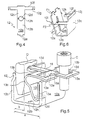
- Figure 3 shows a variant of the reinforcement arm terminal.
- Figure 4 is a plan view of the blank used to make the support part of the figure 3.
- FIG. 5 shows in perspective a variant with a double terminal.
- Figure 6 shows another embodiment of a support arm piece reinforcement for double bollard.
- the electrical appliance part of which is shown schematically in the figure 1 comprises a housing made of insulating material 10 and several terminals with elastic cage Protected by a housing part, a cover or other similar member of recovery 11.
- Terminal A has a conductive support piece 12 bearing on a wing 12a a spring cage 13.
- the spring cage 13 comprises a support wing 13a applied on the wing 12a of the support piece, a clamping wing 13b and a loop 13c; the clamping wing 13b is connected to the support wing 13a by the loop 13c which forms a spring and it has a clamping window 13d into which enters and remains engaged the end of the wing 13a.
- Clamping window 13d has an edge 13e applicable against the side of the wing 12a opposite to that which carries the wing 13a; the window 13d is used to clamp at least one conductor C, with wedging effect between the edge 13th and wing 12a.
- the wing 12a of the part 12 can advantageously offer an end free curved or convex 12e which is introduced into the window 13d of the spring cage and facilitates cable entry.
- the support conductive part 12 is generally U-shaped and has the wing 12a already mentioned, as well as a core 12b and another wing 12c.
- the part 12 is fixed by its core 12b to the connection pad 14a of a main conductive part 14 specific to the device.
- the fixing is carried out by means of a screw 15 with head 15a and threaded body 15b; the head 15a is milled ( Figures 1 and 2) or flat bottom ( Figure 3).
- the head 15a of the screw is applied to the peripheral edge of an orifice 12d provided in the core 12b and the threaded body 15b of the screw engages in a tapped hole 14b formed in the connection area 14a of the part main; the tapped hole and the screw are dimensioned so that the elastic terminal in question can be substituted for a conventional terminal with a conductor clamping screw.
- the head 15a occupies a large part of the length a of the core 12b and allows the screw to occupy a small space in height while leaving a space reserved for the elastic cage 13.
- the screw 15 can be immobilized relative to the part 12 by anti-loosening means, other than the usual threads of its threaded body 15b; these means can be notches, ridges or grooves 15c provided on the underside of the head screw 15a (see figure 2). Alternatively, specific nets of braking 15d in the vicinity of the head 15a and just below it (see figure 3).
- Wing 12c extends substantially parallel to the wing 12a or can be slightly inclined by compared to wing 12a.
- the wing 12c forms a guide branch for a tool B which serves to deform the loop 13c (see Figure 1), in order to clear an opening in the window 13d and thus ensure the passage of the conductor, or for a connection plug D; the wing 12a advantageously has a convex free end 12j (see figure 5).
- the U-shaped support part 12 can advantageously have initially the shape indicated in FIG. 2.
- the wing 12a is open, for example at 45 °, to allow the positioning of the screw 15 in the orifice 12d of the part 12 and then screw it into the orifice 14b of the part 14.
- the spring cage 13 is put in place on the branch 12a of the part 12 then held open before the screw is introduced into the orifice 12d; it can also be placed on the branch 12a after the screw has been introduced into the orifice 12d. Then the screw is screwed into the tapped hole 14b of the main part 14 of the device, then the wing 12a is bent to take its position substantially orthogonal to the core 12b.
- the arrangement described makes it possible to accommodate terminals of small bulk in the apparatus, since the distance a between the wings 12a and 12c of the support piece is reduced.
- the support piece 12 can comprise (see FIGS. 3 and 4) arms 12f coming from folding from wing 12c or respectively from wing 12a and extending transversely to those wings. Each arm is provided at its free end with a 12g finger which can be folded or folded down to engage behind wing 12a (respectively behind the wing 12c) in order to avoid deformation of the wing 12c when the tool B or the plug D applies against it.
- the piece 12 keeps opposite the core 12b a wide opening which allows satisfactory access to conductors C, plugs D and tools B via appropriate openings 11c and 11b, d of the cover 11.
- an anti-rotation measure can be taken to prevent the part 12 from pivot relative to the part 14; it can be a simple stop of the part 12 against the housing or cover of the device; or 14c pins arranged on the room 14 and cooperating with 12h withdrawals provided in room 12 or vice versa (see Figure 4) or legs 12i from part 12 and suitably folded to apply on both sides against the edge of piece 14.
- Piece 12 is obtained by cutting from a sheet of metal sheet as indicated in FIG. 4.
- FIG. 5 shows a double terminal according to the invention.
- the spring cages 13 are housed one next to the other in the part 12.
- a stiffening arm 16 in the form of a bridge takes root on the wing 12c and is supported by a shoulder 16a on the wing 12a, of so that this results in better rigidity for the support piece and for the entire terminal. It can be observed that the distance b provided between the loop 13c of the spring cage 13 and the second wing 12c is sufficient to accommodate between them a connection plug D and that the arrangement adopted makes it possible to accommodate in the same location and under a minimum space requirement a power plug D and a feeder cable C.
- Figure 6 shows an advantageous alternative embodiment of the support piece 12. This is intended to receive two elastic cages side by side as in the case of Figure 5, but could of course receive a single elastic cage. Of them arms 12f coming from folding from the wing 12c extend transversely to the latter to wing 12a to automatically snap onto wing when closing of the support piece 12 (see arrow F1).
- each arm may have a notch (or lug) at its free end 12k intended to cooperate with a lug (or notch) 121 disposed on the side of the wing 12a, ramps and faces of suitable shape being provided on the notches and lugs to facilitate docking during assembly (see arrow F2) and confirm after assembly mutual blocking to resist any effort to open the part 12.
- the arms 12f stay away from it and, when the wing 12a is folded down to take its position final operation in the device, the arms are locked in place and remain retained on the pins.
- the arms 12f may have other forms of latching, fitting or shoulder on the wing 12a.
Landscapes
- Connector Housings Or Holding Contact Members (AREA)
- Connections By Means Of Piercing Elements, Nuts, Or Screws (AREA)
- Coupling Device And Connection With Printed Circuit (AREA)
- Connections Arranged To Contact A Plurality Of Conductors (AREA)
- Details Of Connecting Devices For Male And Female Coupling (AREA)
Description
Selon l'invention, la pièce conductrice de support est sensiblement en forme de U, présentant de part et d'autre de son âme une première aile et une deuxième aile, la première aile constituant une branche de connexion pour le câble à connecter et portant la cage-ressort, la deuxième aile constituant une branche de guidage pour un outil de manoeuvre ou une fiche de connexion.
La pièce conductrice principale comprend une plage de connexion à trou taraudé coaxial à l'orifice de l'âme, tandis qu'une vis traverse l'orifice et coopère avec le trou taraudé pour presser la pièce de support sur la pièce principale.
Claims (8)
- Appareil électrique comprenant des bornes de connexion à cage élastique dont chacune présente une pièce conductrice de support (12) qui est une pièce intermédiaire présentant une âme (12b), munie d'un orifice (12d), assemblée à une pièce conductrice principale (14) propre à l'appareil, et qui porte près d'une extrémité une cage élastique (13), cette cage élastique comprenant une aile d'appui (13a) appliquée sur la pièce conductrice de support, une aile de serrage (13b) reliée à l'aile d'appui par une boucle (13c) formant ressort et dotée d'une fenêtre de serrage (13d) de conducteur par effet de coincement, caractérisé par le fait que :la pièce conductrice de support (12) est sensiblement en forme de U, avec de part et d'autre de l'âme (12b) une première aile (12a) formant branche de connexion pour un câble (C) à connecter et portant la cage élastique (13), et une deuxième aile (12c) constituant une branche de guidage par exemple pour un outil de manoeuvre (B),la pièce conductrice principale (14) comprend une plage de connexion (14a) à trou taraudé (14b) coaxial à l'orifice (12d) de l'âme (12b), tandis qu'une vis (15) traverse l'orifice (12d) et coopère avec le trou taraudé (14b) pour presser la pièce de support (12) sur la pièce principale (14).
- Appareil selon la revendication 1, caractérisé par le fait que la vis (15) présente des moyens d'antidesserrage assurant son immobilisation par rapport à la pièce de support (12).
- Appareil selon la revendication 1, caractérisé par le fait que la vis (15) présente des moyens d'antidesserrage assurant son immobilisation par rapport à la pièce principale (14).
- Appareil selon la revendication 1, caractérisé par le fait que des éléments (12h,14c) empêchant la rotation de la pièce de support (12) sont associés à la pièce de support (12) et à la pièce principale (14).
- Appareil selon la revendication 1, caractérisé par le fait que la première aile (12a) de la pièce de support (12) est inclinée avant pose de la vis (15) de manière à ménager un passage pour la vis ou un outil de manoeuvre de celle-ci, et est rabattue après pose de la cage-ressort (13) et de la vis (15) pour prendre une position sensiblement orthogonale à l'âme (12b).
- Appareil selon la revendication 1, caractérisé par le fait que la pièce de support (12) comporte au moins un bras de renfort (12f) plié à partir de l'une des ailes (12a,12c), transversalement vers l'autre aile (12c,12a), et bloqué par un élément de forme convenable (12g,12k ; 16a) contre celle-ci.
- Appareil selon la revendication 6, caractérisé par le fait que le bras de renfort (12f) est encliqueté automatiquement sur l'autre aile lors du rabattement de la première aile.
- Appareil selon la revendication 1, caractérisé par le fait que la pièce de support (12) est ménagée pour recevoir deux cages élastiques (13) côte à côte dans une direction parallèle aux ailes et comprend au moins un bras de renfort (12f; 16) joignant les deux ailes (12a, 12c).
Priority Applications (1)
| Application Number | Priority Date | Filing Date | Title |
|---|---|---|---|
| EP01202574A EP1156551A1 (fr) | 1997-07-21 | 1998-07-03 | Appareil électrique à bornes dotées de cages élastiques |
Applications Claiming Priority (2)
| Application Number | Priority Date | Filing Date | Title |
|---|---|---|---|
| FR9709397A FR2766298B1 (fr) | 1997-07-21 | 1997-07-21 | Appareil electrique a bornes dotees de cages elastiques |
| FR9709397 | 1997-07-21 |
Related Child Applications (1)
| Application Number | Title | Priority Date | Filing Date |
|---|---|---|---|
| EP01202574A Division EP1156551A1 (fr) | 1997-07-21 | 1998-07-03 | Appareil électrique à bornes dotées de cages élastiques |
Publications (2)
| Publication Number | Publication Date |
|---|---|
| EP0893847A1 EP0893847A1 (fr) | 1999-01-27 |
| EP0893847B1 true EP0893847B1 (fr) | 2002-03-20 |
Family
ID=9509565
Family Applications (2)
| Application Number | Title | Priority Date | Filing Date |
|---|---|---|---|
| EP01202574A Ceased EP1156551A1 (fr) | 1997-07-21 | 1998-07-03 | Appareil électrique à bornes dotées de cages élastiques |
| EP98401683A Expired - Lifetime EP0893847B1 (fr) | 1997-07-21 | 1998-07-03 | Appareil électrique à bornes dotées de cages élastiques |
Family Applications Before (1)
| Application Number | Title | Priority Date | Filing Date |
|---|---|---|---|
| EP01202574A Ceased EP1156551A1 (fr) | 1997-07-21 | 1998-07-03 | Appareil électrique à bornes dotées de cages élastiques |
Country Status (7)
| Country | Link |
|---|---|
| EP (2) | EP1156551A1 (fr) |
| JP (1) | JP4124865B2 (fr) |
| KR (1) | KR100317686B1 (fr) |
| CN (1) | CN1125504C (fr) |
| DE (1) | DE69804275T2 (fr) |
| ES (1) | ES2172098T3 (fr) |
| FR (1) | FR2766298B1 (fr) |
Families Citing this family (7)
| Publication number | Priority date | Publication date | Assignee | Title |
|---|---|---|---|---|
| FR2789525B1 (fr) | 1999-02-05 | 2001-03-16 | Schneider Electric Sa | Appareil interrupteur electrique et ensemble a assemblage rapide |
| ES2157819B1 (es) * | 1999-08-13 | 2002-03-01 | Tecnica De Conexiones S A | Borne de conexion para luminarias. |
| JP4898483B2 (ja) * | 2007-02-16 | 2012-03-14 | 東芝エレベータ株式会社 | 照明ユニット、照明装置、およびエレベータの乗籠 |
| DE502007005846D1 (de) * | 2007-06-29 | 2011-01-13 | Siemens Ag | Elektrisches Gerät mit einer Federklemmeinheit |
| FR3046702B1 (fr) * | 2016-01-08 | 2019-07-26 | Tyco Electronics Services Gmbh | Borne de connexion pour appareil electrique equipee d'une cage de serrage en materiau amagnetique |
| DE202016100281U1 (de) | 2016-01-21 | 2017-01-26 | Hora-Werk Gmbh | Sammelschienenabgreifklemme mit Klemmfedertechnik |
| CN113488825A (zh) * | 2021-07-02 | 2021-10-08 | 苏州思科赛德电子科技有限公司 | 一种杠杆式压线工具 |
Citations (1)
| Publication number | Priority date | Publication date | Assignee | Title |
|---|---|---|---|---|
| US5184100A (en) * | 1990-04-26 | 1993-02-02 | Fuji Electric Co., Ltd. | Circuit breaker |
Family Cites Families (4)
| Publication number | Priority date | Publication date | Assignee | Title |
|---|---|---|---|---|
| US1688182A (en) * | 1926-04-14 | 1928-10-16 | Harmon C Shear | Terminal connecter |
| DE3504317A1 (de) * | 1985-02-08 | 1986-08-14 | Licentia Patent-Verwaltungs-Gmbh, 6000 Frankfurt | Klemme fuer elektrische leiter |
| CH667553A5 (de) * | 1985-10-09 | 1988-10-14 | Woertz Oskar | Schraubenlose elektrische klemme. |
| FR2669778B1 (fr) * | 1990-11-22 | 1994-07-22 | Rapid Sa | Cale de positionnement bloque pour une cosse de connexion electrique. |
-
1997
- 1997-07-21 FR FR9709397A patent/FR2766298B1/fr not_active Expired - Fee Related
-
1998
- 1998-07-03 DE DE69804275T patent/DE69804275T2/de not_active Expired - Lifetime
- 1998-07-03 EP EP01202574A patent/EP1156551A1/fr not_active Ceased
- 1998-07-03 ES ES98401683T patent/ES2172098T3/es not_active Expired - Lifetime
- 1998-07-03 EP EP98401683A patent/EP0893847B1/fr not_active Expired - Lifetime
- 1998-07-20 KR KR1019980029107A patent/KR100317686B1/ko not_active Expired - Fee Related
- 1998-07-21 JP JP20541598A patent/JP4124865B2/ja not_active Expired - Fee Related
- 1998-07-21 CN CN98117525A patent/CN1125504C/zh not_active Expired - Fee Related
Patent Citations (1)
| Publication number | Priority date | Publication date | Assignee | Title |
|---|---|---|---|---|
| US5184100A (en) * | 1990-04-26 | 1993-02-02 | Fuji Electric Co., Ltd. | Circuit breaker |
Also Published As
| Publication number | Publication date |
|---|---|
| DE69804275T2 (de) | 2002-10-17 |
| FR2766298B1 (fr) | 1999-09-17 |
| KR19990014000A (ko) | 1999-02-25 |
| FR2766298A1 (fr) | 1999-01-22 |
| JP4124865B2 (ja) | 2008-07-23 |
| JPH11121055A (ja) | 1999-04-30 |
| KR100317686B1 (ko) | 2002-02-19 |
| DE69804275D1 (de) | 2002-04-25 |
| EP1156551A1 (fr) | 2001-11-21 |
| EP0893847A1 (fr) | 1999-01-27 |
| ES2172098T3 (es) | 2002-09-16 |
| CN1209663A (zh) | 1999-03-03 |
| CN1125504C (zh) | 2003-10-22 |
Similar Documents
| Publication | Publication Date | Title |
|---|---|---|
| EP3323171B1 (fr) | Isolateur pour une connexion électrique pivotable | |
| EP1024553A1 (fr) | Connecteur électrique pour câble plat | |
| FR2510312A1 (fr) | Connecteur de blindage pour cables blindes | |
| FR2711452A1 (fr) | Elément de connexion comportant un pontet isolant. | |
| FR2546341A1 (fr) | Connecteur electrique multipolaire, notamment cylindrique | |
| EP0338868B1 (fr) | Appareil modulaire de protection ou de commande électrique | |
| EP0893847A1 (fr) | Appareil électrique à bornes dotées de cages élastiques | |
| JP3526240B2 (ja) | 電気接続箱の端子接続構造 | |
| EP0896387B1 (fr) | Borne à vis et bornier pour appareil électrique. | |
| FR2766297A1 (fr) | Appareil electrique portant un support de contact fixe et une borne de raccordement | |
| EP0928043A1 (fr) | Dispositif de connexion à cage élastique | |
| FR2795560A1 (fr) | Serre-fil muni d'un dispositif de protection contre le toucher | |
| EP0552114B1 (fr) | Borne de raccordement multiple pour appareillage électrique modulaire | |
| FR2579026A2 (fr) | Dispositif de raccord pour une embase d'antenne destinee a etre fixee sur une paroi et capuchon d'antiparasitage pour un tel dispositif | |
| FR2649251A1 (fr) | Organe de contact electrique femelle | |
| EP0509859B1 (fr) | Organe de contact électrique femelle | |
| EP0643444A1 (fr) | Contact électrique à rappel élastique | |
| EP3109943B1 (fr) | Dispositif de liaison électrique pour un appareil électrique | |
| EP0817318A1 (fr) | Borne d'arrivée pour barre d'alimentation en forme de peigne, notamment pour appareils électriques modulaires | |
| FR2748150A1 (fr) | Plot de charge pour appareil portable a batterie rechargeable | |
| FR2734422A1 (fr) | Support d'appareil electrique pour goulotte a rails | |
| FR2655487A1 (fr) | Appareil pour installation electrique. | |
| FR2656742A1 (fr) | Element detrompeur pour dispositifs de connexion destines au branchement de derivations sur des cables principaux. | |
| FR2818022A1 (fr) | Bornier destine au branchement provisoire a un reseau electrique d'une installation electrique, par exemple du type mobile | |
| EP0170547B1 (fr) | Perfectionnements aux structures d'antennes |
Legal Events
| Date | Code | Title | Description |
|---|---|---|---|
| PUAI | Public reference made under article 153(3) epc to a published international application that has entered the european phase |
Free format text: ORIGINAL CODE: 0009012 |
|
| AK | Designated contracting states |
Kind code of ref document: A1 Designated state(s): DE ES GB IT |
|
| AX | Request for extension of the european patent |
Free format text: AL;LT;LV;MK;RO;SI |
|
| 17P | Request for examination filed |
Effective date: 19981203 |
|
| RAP1 | Party data changed (applicant data changed or rights of an application transferred) |
Owner name: SCHNEIDER ELECTRIC INDUSTRIES SA |
|
| AKX | Designation fees paid |
Free format text: DE ES GB IT |
|
| 17Q | First examination report despatched |
Effective date: 19990917 |
|
| RAP1 | Party data changed (applicant data changed or rights of an application transferred) |
Owner name: SCHNEIDER ELECTRIC INDUSTRIES SA |
|
| GRAG | Despatch of communication of intention to grant |
Free format text: ORIGINAL CODE: EPIDOS AGRA |
|
| GRAG | Despatch of communication of intention to grant |
Free format text: ORIGINAL CODE: EPIDOS AGRA |
|
| GRAH | Despatch of communication of intention to grant a patent |
Free format text: ORIGINAL CODE: EPIDOS IGRA |
|
| GRAH | Despatch of communication of intention to grant a patent |
Free format text: ORIGINAL CODE: EPIDOS IGRA |
|
| REG | Reference to a national code |
Ref country code: GB Ref legal event code: IF02 |
|
| GRAA | (expected) grant |
Free format text: ORIGINAL CODE: 0009210 |
|
| AK | Designated contracting states |
Kind code of ref document: B1 Designated state(s): DE ES GB IT |
|
| REF | Corresponds to: |
Ref document number: 69804275 Country of ref document: DE Date of ref document: 20020425 |
|
| GBT | Gb: translation of ep patent filed (gb section 77(6)(a)/1977) |
Effective date: 20020524 |
|
| REG | Reference to a national code |
Ref country code: ES Ref legal event code: FG2A Ref document number: 2172098 Country of ref document: ES Kind code of ref document: T3 |
|
| RAP2 | Party data changed (patent owner data changed or rights of a patent transferred) |
Owner name: SCHNEIDER ELECTRIC INDUSTRIES SAS |
|
| PLBE | No opposition filed within time limit |
Free format text: ORIGINAL CODE: 0009261 |
|
| STAA | Information on the status of an ep patent application or granted ep patent |
Free format text: STATUS: NO OPPOSITION FILED WITHIN TIME LIMIT |
|
| 26N | No opposition filed |
Effective date: 20021223 |
|
| PGFP | Annual fee paid to national office [announced via postgrant information from national office to epo] |
Ref country code: DE Payment date: 20140605 Year of fee payment: 17 |
|
| PGFP | Annual fee paid to national office [announced via postgrant information from national office to epo] |
Ref country code: GB Payment date: 20140717 Year of fee payment: 17 Ref country code: ES Payment date: 20140725 Year of fee payment: 17 |
|
| PGFP | Annual fee paid to national office [announced via postgrant information from national office to epo] |
Ref country code: IT Payment date: 20140714 Year of fee payment: 17 |
|
| REG | Reference to a national code |
Ref country code: DE Ref legal event code: R119 Ref document number: 69804275 Country of ref document: DE |
|
| GBPC | Gb: european patent ceased through non-payment of renewal fee |
Effective date: 20150703 |
|
| PG25 | Lapsed in a contracting state [announced via postgrant information from national office to epo] |
Ref country code: IT Free format text: LAPSE BECAUSE OF NON-PAYMENT OF DUE FEES Effective date: 20150703 Ref country code: DE Free format text: LAPSE BECAUSE OF NON-PAYMENT OF DUE FEES Effective date: 20160202 Ref country code: GB Free format text: LAPSE BECAUSE OF NON-PAYMENT OF DUE FEES Effective date: 20150703 |
|
| REG | Reference to a national code |
Ref country code: ES Ref legal event code: FD2A Effective date: 20160826 |
|
| PG25 | Lapsed in a contracting state [announced via postgrant information from national office to epo] |
Ref country code: ES Free format text: LAPSE BECAUSE OF NON-PAYMENT OF DUE FEES Effective date: 20150704 |