EP0893381A2 - Method of and device for handling webs having adhesive - Google Patents
Method of and device for handling webs having adhesive Download PDFInfo
- Publication number
- EP0893381A2 EP0893381A2 EP98112322A EP98112322A EP0893381A2 EP 0893381 A2 EP0893381 A2 EP 0893381A2 EP 98112322 A EP98112322 A EP 98112322A EP 98112322 A EP98112322 A EP 98112322A EP 0893381 A2 EP0893381 A2 EP 0893381A2
- Authority
- EP
- European Patent Office
- Prior art keywords
- material web
- bobbin
- adhesive
- section
- running
- Prior art date
- Legal status (The legal status is an assumption and is not a legal conclusion. Google has not performed a legal analysis and makes no representation as to the accuracy of the status listed.)
- Granted
Links
Images


Classifications
-
- B—PERFORMING OPERATIONS; TRANSPORTING
- B65—CONVEYING; PACKING; STORING; HANDLING THIN OR FILAMENTARY MATERIAL
- B65H—HANDLING THIN OR FILAMENTARY MATERIAL, e.g. SHEETS, WEBS, CABLES
- B65H19/00—Changing the web roll
- B65H19/10—Changing the web roll in unwinding mechanisms or in connection with unwinding operations
- B65H19/18—Attaching, e.g. pasting, the replacement web to the expiring web
- B65H19/1857—Support arrangement of web rolls
- B65H19/1868—The roll support being of the turret type
-
- B—PERFORMING OPERATIONS; TRANSPORTING
- B65—CONVEYING; PACKING; STORING; HANDLING THIN OR FILAMENTARY MATERIAL
- B65H—HANDLING THIN OR FILAMENTARY MATERIAL, e.g. SHEETS, WEBS, CABLES
- B65H19/00—Changing the web roll
- B65H19/10—Changing the web roll in unwinding mechanisms or in connection with unwinding operations
- B65H19/18—Attaching, e.g. pasting, the replacement web to the expiring web
- B65H19/1842—Attaching, e.g. pasting, the replacement web to the expiring web standing splicing, i.e. the expiring web being stationary during splicing contact
- B65H19/1852—Attaching, e.g. pasting, the replacement web to the expiring web standing splicing, i.e. the expiring web being stationary during splicing contact taking place at a distance from the replacement roll
-
- B—PERFORMING OPERATIONS; TRANSPORTING
- B65—CONVEYING; PACKING; STORING; HANDLING THIN OR FILAMENTARY MATERIAL
- B65H—HANDLING THIN OR FILAMENTARY MATERIAL, e.g. SHEETS, WEBS, CABLES
- B65H2301/00—Handling processes for sheets or webs
- B65H2301/40—Type of handling process
- B65H2301/46—Splicing
- B65H2301/462—Form of splice
- B65H2301/4621—Overlapping article or web portions
-
- B—PERFORMING OPERATIONS; TRANSPORTING
- B65—CONVEYING; PACKING; STORING; HANDLING THIN OR FILAMENTARY MATERIAL
- B65H—HANDLING THIN OR FILAMENTARY MATERIAL, e.g. SHEETS, WEBS, CABLES
- B65H2301/00—Handling processes for sheets or webs
- B65H2301/40—Type of handling process
- B65H2301/46—Splicing
- B65H2301/463—Splicing splicing means, i.e. means by which a web end is bound to another web end
- B65H2301/4631—Adhesive tape
-
- B—PERFORMING OPERATIONS; TRANSPORTING
- B65—CONVEYING; PACKING; STORING; HANDLING THIN OR FILAMENTARY MATERIAL
- B65H—HANDLING THIN OR FILAMENTARY MATERIAL, e.g. SHEETS, WEBS, CABLES
- B65H2301/00—Handling processes for sheets or webs
- B65H2301/40—Type of handling process
- B65H2301/46—Splicing
- B65H2301/464—Splicing effecting splice
- B65H2301/4641—Splicing effecting splice by pivoting element
-
- B—PERFORMING OPERATIONS; TRANSPORTING
- B65—CONVEYING; PACKING; STORING; HANDLING THIN OR FILAMENTARY MATERIAL
- B65H—HANDLING THIN OR FILAMENTARY MATERIAL, e.g. SHEETS, WEBS, CABLES
- B65H2701/00—Handled material; Storage means
- B65H2701/30—Handled filamentary material
- B65H2701/37—Tapes
- B65H2701/377—Adhesive tape
Definitions
- the invention relates to methods and apparatus for handling of material webs with one-sided coating of an adhesive, in particular for applying sections of an adhesive strip on folding boxes, the material web or the adhesive strip is subtracted from a first bobbin and according to consumption same a new material web / a new adhesive strip is connected to the running material web.
- Roll material coated on one side with active adhesive or adhesive strips are used, for example, to close Cardboard boxes used.
- a so-called tape unit carries the Adhesive strips for example on the top and on the bottom in the area of adjoining locking tabs on the Cardboard box open.
- the adhesive strip consists of a plastic sheet with active adhesive applied on one side.
- the material web or the adhesive strip is as (wound) Bobine provided. After consumption of the same a new material web or a new adhesive strip with if possible little effort to be connected to the expiring.
- the invention is therefore based on the object of a method and to propose a device which is suitable for a simple, reliable handling of adhesive strips, in particular when connecting a new adhesive strip to a running, to ensure.
- the method according to the invention is used to achieve this object characterized in that the new adhesive strip or New course with a free start section for connection to the runway with the glue-free side facing the adhesive side of the runway is pressed.
- the beginning section of the new track is by - machine or manually - operated cold available, on which the Start section of the adhesive-containing side.
- the Contact area of the holder is designed so that the holding force sufficient for the initial section to complete this up to the plant to fix on the runway.
- By contacting the adhesive Side of the runway will have a greater holding force generated which resulted in the beginning section on the runway Adhesive fixed so that the cold from the initial section the new course can be solved.
- the holder for the initial section of the new track is a movable, in particular pivoting arm, which is the beginning section by transverse movement to the runway in the area of a deflection the same, especially in the region of a deflecting roller, presses.
- Another special feature of the invention is that the active bobbin, from which the material web is pulled, up to full consumption is driven empty. So there is none Remaining section of the material web on the bobbin or on a Bobbin core.
- special measures are provided that even after pulling off the end portion of the web a certain tension from the bobbin or the bobbin core remains in the material web, so that this without Warping, wrinkling or the like until connection the new material web can be transported.
- the purpose of the invention is a cross-sectional deformation of the running Material web provided.
- a common, pivotable carrier in particular on a support plate, two Arranged bobbins of the adhesive strip, namely a drain bobbin and a replacement bobbin from which the new track is pulled.
- the drain bobbin is turned in by turning the support disc a predetermined drain position and the replacement bobbin in one Waiting position moved.
- the initial section of the new railway will be preferably manually removed from the replacement bobbin and to the Holder created.
- the device shown in Fig. 1 is concerned with the attachment an adhesive tape 10 on a folding box 11.
- An upper one is used to apply the adhesive strips 10 and lower tape unit 12, 13, which automatically has an adhesive strip 10 attaches to the folding box 11.
- the adhesive strip 10 is a continuous strip or a continuous web of material 14 separated. This exists preferably made of plastic and is one-sided with an active Adhesive 15 coated.
- the material web 14 is a bobbin 16 removed and fed to the tape unit 12, 13.
- the Bobine 16 is located in a splice station 17 together with a replacement bobbin 18.
- In the present embodiment is the device with two matching splice stations 17 equipped to independently each tape unit 12, 13 with Supply material.
- the active bobbin 16 When the active bobbin 16 is used up, it takes place in the area Splicestation 17 a largely automatic connection of the replacement bobbin 18 to the running material web 14 instead.
- the present example is a certain manual one Use for changing the bobbin.
- the replacement bobbin 18 becomes during the pulling off of the material web 14 prepared by the (active) bobbin 16 for a change.
- an initial section 19 is (manually) from the Replacement bobbin 18 removed and adjacent to the material web 14 kept ready.
- the replacement bobbin 18 After partial or complete deduction of the Material web 14 from the bobbin 16 becomes the initial section 19 the replacement bobbin 18 to an end portion 20 of the expiring Material web 14 pressed and so the connection of the material web 14 made with the replacement bobbin 18.
- the splicing station 17 is used to carry out the lane change provided automatically working organs.
- the (ongoing) Material web 14 is at the exit of the splice station 17 via Guide element guided, namely via a guide roller 21.
- the material web 14 is wound on the bobbin 16 so that the one-sided attached to the web of adhesive 15 in the area of Deflection roller 21 faces outwards.
- the deflection roller 21 is mounted at a distance from the bobbin 16, on an (upright) supporting wall 22.
- the one from the bobbin 16 removed material web 14 is via a guide the deflection roller 21 supplied, namely via a Shoe 23.
- This is designed as an elongated, one-armed lever with a (lower) pivot bearing 24 adjacent to the deflection roller 21, above it.
- the shoe 23 has a guide surface 25 for the material web 14 provided.
- the shoe 23 is - seen in cross section - formed as an elongated hollow body with a corresponding Cross-sectional contour of the guide surface 25.
- As in particular 6 shows the shoe 23 in cross section approximately C-shaped, that is, open on one side Profile.
- the guide surface 25 forms obliquely at the edges Side strips 26, 27. These go to the free Outer edges over in angled guide leg 28, 29.
- the material web 14 runs continuously on that described in the Way contoured guide surface 25 along and thereby receives a corresponding, shaped cross-sectional shape.
- the material web 14 runs continuously on that described in the Way contoured guide surface 25 along and thereby receives a corresponding, shaped cross-sectional shape.
- the material web 14 in its longitudinal direction is deformed, i.e. in particular wrinkles.
- the shoe 23 due to the design of the guide surface 25 a holding force on the transported material web 14 it is possible with this device, the respective bobbin 16 to run completely empty, i.e. without disconnecting one Remaining part of the material web 14, which remains on the bobbin 16.
- a special feature lies in this and in the design of the shoe 23 the device.
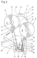
- the shoe 23 is swiveled out the plane of movement of the material web 14 moved out into a Position shown in phantom in Fig. 2. After this Changing the bobbin, the shoe 23 is brought back into position, in which the material web 14 rests on the guide surface 25.
- the replacement bobbin 18 or its initial section 19 is adjacent to the deflection roller 21 for connection to the material web 14 kept ready.
- the initial section 19 lies on a transmission element on, namely on a transfer roller 30, which in turn at the lower or free end of a one-armed transmission lever 31 is stored.
- the latter is adjacent in the area of one pivot bearing 32 arranged for replacement bobbin 18 swiveling. This is also arranged on the common support wall 22.
- the relative position is chosen so that at a Pivoting movement according to arrow 33, the transfer roller 30 from the Starting position according to FIG. 2 in the transfer position Fig. 4 is pivoted. In this, the transfer roller 30 is immediate adjacent to the circumference of the deflection roller 21, namely such that a free end of the start section 19 to the material web 14 is pressed in the region of the deflecting roller 21.
- the replacement bobbin 18 is positioned so that the initial section 19 with the adhesive 15 of the transfer roller 30 and the Transmission lever 31 is turned.
- the initial section 19 is therefore with an adhesive surface on the circumference of the transfer roller 30 and - in the present embodiment - on Transmission lever 31 on.
- Transfer roller 30 and / or transfer lever 31 are designed that on the one hand the one with the adhesive side Material web is kept sufficient, but on the other hand Press on a side of the material web provided with adhesive 15 14 this detects the end of the beginning section 19 and of the transfer roller 30 or the transmission lever 31 deducts.
- the transfer roller 30 along the circumference Provide projections or increases. It is in the present case around protruding tips 34 which are here pyramid-shaped ridges 35 are formed. The increases 35 and thus their tips 34 are in the present case in longitudinal and transverse rows in regular distribution along the The circumference of the transfer roller 30 is arranged.
- the holding piece 36 is the same here Way as the transfer roller 30 with ridges 35 and 34 tips Mistake.
- the connection of the start section 19 of the new material web the running material web 14 is carried out automatically.
- the running bobbin 16 is driven completely empty.
- the end of the material web 14 is scanned.
- an expiring Lane 14 observing photocell 37 is provided.
- a rotating bearing of the bobbin 16 with a rotating one non-contact button, for example an initiator can in the area of a rotating bearing of the bobbin 16 with a rotating one non-contact button, for example an initiator, be formed, the standstill after the end of the material web 14 the bobbin holder or the reduced rotation speed as a signal for the complete removal of the material web 14 recognizes.
- the transmission lever 31 is described in the Senses swiveled up to the circumference of the deflection roller 21.
- the pivoting movement of the transmission lever 31 is caused by an actuator actuated by the photocell 37, namely by an (electric) cylinder 38, the piston rod 39 on a transverse arm 40 of the transmission lever 31 connected.
- the replacement bobbin 18 is in the present embodiment manually prepared for connection.
- the beginning section 19 is removed by hand from the replacement bobbin 18 and in the position described, bearing on the transfer roller 30 and transmission lever 31 brought.
- Below the transfer roller 30 there is a stationary knife 41 End of the initial section 19 separated, so that the initial section 19 always in an exact relative position Transfer roller 30 receives. It also has an exact end edge created by the knife 41.
- the knife 41 is also on the support wall 22 attached.
- the device or the splice station 17 is equipped with monitoring devices provided that the presence of material, namely the material web 14 monitored at the important areas.
- the rotational movement of the Deflection roller 21, on the one hand the presence of the material web 14 assumes.
- it can also be the correct one Deduction of the adhesive strips 10 are monitored, namely in terms of length.
- control disc 65 with (three) at equal circumferential distances from each other arranged radial projections 66 provided and on arranged a shaft for the deflection roller 21, that is, with this rotating.
- the initiator 64 is rotated by the protrusions 66 Control disc 65 applied. This will become basically recognizes the rotational movement of the deflection roller 21, on the other hand also the length of the stripped section the material web 14.
- the bobbins 16, 18 are adjustable, namely on a pivotable or rotatable member. It in the present case, this is an (upright) Support disc 42. This is rotatably supported by a central bearing 43, namely on the support wall 22. The support disc 42 is after each bobbin change rotated so that the replacement bobbin 18 reaches the position of the active bobbin 16. The support disk 42 is rotated clockwise according to arrow 44.
- the material web 14 comes from the area of the replacement bobbin 18 to rest on the shoe 23, the material web 14 with cross-sectional deformation in the cavity of the shoe 23 entry.
- the Shoe 23 pivotable about the (lower) pivot bearing 24 in the dash-dotted lines position shown in FIG. 2. In this position the rotation of the support disk 42 is carried out. Of the Shoe 23 is then pivoted back into the working position and takes up the material web 14.
- the support disk 42 is manual in this embodiment rotatable. Handles are provided for this purpose one handle 45, 46 each in the area of a reel bearing 47, 48. The transversely protruding handles 45, 46 can be grasped and so the Carrier disc 42 are rotated.
- the working position of the support plate 42 is fixed, namely by a locking pin, which can also be operated with handle 49 enters a locking hole 50 of the support plate 42 for fixation the same on a bracket, namely on the support wall 22nd
- the handles 45, 46 in the area of the reel bearings 47, 48 have a double function.
- the handles practice one by means of springs 51 axially directed pressure on the reels 16, 18 or on a Bobbin core 52 out. This creates a braking effect due to friction generated in the area of the reels 16, 18.
- the braking effect is adjustable with the help of knurled wheels 53, which are used for change the tension of the springs 51 can be adjusted.
- the device is overall on a portal-like Support frame 54 attached.
- the two on top of each other arranged splice stations 17 or their support wall 22 is on an upright support 55 of the support frame 54 is attached.
- On an opposite support 56 are the two tape units 12, 13 mounted on a bracket 57. This has one upper and lower transversely projecting support arm 58, 59.
- At the end a tape unit 12, 13 is mounted on each support arm.
- Each Tape aggregate 12, 13 is with a guide 60, 61 on the Support arm 58, 59 slidable, so that an exact position each Tape aggregates 12, 13 can be done in the horizontal direction.
- one of the tape aggregates 12, 13 is in the present Fall the top tape aggregate 12 in the vertical direction adjustable to adapt to different formats of the folding boxes 11.
- the support arm 58 has a vertical guide 62 connected. This is on an upright in the vertical direction Support rod 63 slidable. This is part of the bracket 57.
Abstract
Description
Die Erfindung betrifft Verfahren und Vorrichtung zum Handhaben von Material bahnen mit einseitiger Beschichtung eines Klebstoffes, insbesondere zum Auftragen von Abschnitten eines Klebestreifens auf Faltkartons, wobei die Materialbahn bzw. der Klebestreifen von einer ersten Bobine abgezogen wird und nach Verbrauch derselben eine neue Materialbahn/ein neuer Klebestreifen an die ablaufende Materialbahn angeschlossen wird.The invention relates to methods and apparatus for handling of material webs with one-sided coating of an adhesive, in particular for applying sections of an adhesive strip on folding boxes, the material web or the adhesive strip is subtracted from a first bobbin and according to consumption same a new material web / a new adhesive strip is connected to the running material web.
Mit aktivem Klebstoff einseitig beschichtete Material bahnen bzw. Klebestreifen werden beispielsweise zum Verschließen von Faltkartons eingesetzt. Ein sogenanntes Tape-Aggregat trägt den Klebestreifen beispielsweise an der Oberseite und an der Unterseite im Bereich von aneinanderstoßenden Schließlappen auf den Faltkarton auf. Der Klebestreifen besteht aus einer Kunststoffbahn mit einseitig aufgetragenem, aktivem Klebstoff.Roll material coated on one side with active adhesive or adhesive strips are used, for example, to close Cardboard boxes used. A so-called tape unit carries the Adhesive strips for example on the top and on the bottom in the area of adjoining locking tabs on the Cardboard box open. The adhesive strip consists of a plastic sheet with active adhesive applied on one side.
Die Materialbahn bzw. der Klebestreifen wird als (gewickelte) Bobine zur Verfügung gestellt. Nach Verbrauch derselben soll eine neue Materialbahn bzw. ein neuer Klebestreifen mit möglichst geringem Aufwand an die ablaufende angeschlossen werden.The material web or the adhesive strip is as (wound) Bobine provided. After consumption of the same a new material web or a new adhesive strip with if possible little effort to be connected to the expiring.
Der Erfindung liegt demnach die Aufgabe zugrunde, ein Verfahren und eine Vorrichtung vorzuschlagen, die geeignet sind, eine einfache, zuverlässige Handhabung von Klebestreifen, insbesondere beim Anschluß eines neuen Klebestreifens an einen ablaufenden, zu gewahrleisten.The invention is therefore based on the object of a method and to propose a device which is suitable for a simple, reliable handling of adhesive strips, in particular when connecting a new adhesive strip to a running, to ensure.
Zur Lösung dieser Aufgabe ist das erfindungsgemäße Verfahren dadurch gekennzeichnet, daß der neue Klebestreifen bzw. die Neubahn mit einem freien Anfangsabschnitt zur Verbindung mit der Ablaufbahn mit der klebstofffreien Seite an die zugekehrte, klebstoffaufweisende Seite der Ablaufbahn gedrückt wird.The method according to the invention is used to achieve this object characterized in that the new adhesive strip or New course with a free start section for connection to the runway with the glue-free side facing the adhesive side of the runway is pressed.
Der Anfangsabschnitt der Neubahn wird durch einen - maschinell oder manuell - betätigbaren Kalter bereitgehalten, an dem der Anfangsabschnitt der klebstoffaufweisenden Seite anliegt. Der Anlagebereich des Halters ist so ausgebildet, daß die Haltekraft für den Anfangsabschnitt ausreicht, um diesen bis zur Anlage an der Ablaufbahn zu fixieren. Durch Anlage an der klebstoffaufweisenden Seite der Ablaufbahn wird eine größere Haltekraft erzeugt, die den Anfangsabschnitt an der Ablaufbahn infolge Klebung fixiert, so daß der Kalter von dem Anfangsabschnitt der Neubahn gelöst werden kann.The beginning section of the new track is by - machine or manually - operated cold available, on which the Start section of the adhesive-containing side. Of the Contact area of the holder is designed so that the holding force sufficient for the initial section to complete this up to the plant to fix on the runway. By contacting the adhesive Side of the runway will have a greater holding force generated which resulted in the beginning section on the runway Adhesive fixed so that the cold from the initial section the new course can be solved.
Der Halter für den Anfangsabschnitt der Neubahn ist ein bewegbarer, insbesondere schwenkbarer Arm, der den Anfangsabschnitt durch Querbewegung an die Ablaufbahn im Bereich einer Umlenkung derselben, insbesondere im Bereich einer Umlenkwalze, andrückt.The holder for the initial section of the new track is a movable, in particular pivoting arm, which is the beginning section by transverse movement to the runway in the area of a deflection the same, especially in the region of a deflecting roller, presses.
Eine weitere Besonderheit der Erfindung besteht darin, daß die aktive Bobine, von der die Materialbahn abgezogen wird, bis zum vollständigen Verbrauch leergefahren wird. Es bleibt also kein Restabschnitt der Materialbahn auf der Bobine bzw. auf einem Bobinenkern. Bei der Erfindung sind besondere Maßnahmen vorgesehen, daß auch nach dem Abziehen des Endabschnitts der Materialbahn von der Bobine bzw. dem Bobinenkern eine gewisse Spannung in der Materialbahn erhalten bleibt, so daß diese ohne Verwerfungen, Faltenbildung oder dergleichen bis zum Anschluß der neuen Materialbahn transportiert werden kann. Zu diesem Zweck ist erfindungsgemäß eine Querschnittsverformung der ablaufenden Materialbahn vorgesehen.Another special feature of the invention is that the active bobbin, from which the material web is pulled, up to full consumption is driven empty. So there is none Remaining section of the material web on the bobbin or on a Bobbin core. In the invention, special measures are provided that even after pulling off the end portion of the web a certain tension from the bobbin or the bobbin core remains in the material web, so that this without Warping, wrinkling or the like until connection the new material web can be transported. To this The purpose of the invention is a cross-sectional deformation of the running Material web provided.
Im Bereich einer Splicestation sind an einem gemeinsamen, schwenkbaren Träger, insbesondere an einer Tragscheibe, zwei Bobinen des Klebestreifens angeordnet, nämlich eine Ablaufbobine und eine Ersatzbobine, von der die Neubahn abgezogen wird. Durch Drehen der Tragscheibe wird die Ablaufbobine jeweils in eine vorgegebene Ablaufstellung und die Ersatzbobine in eine Wartestellung bewegt. Der Anfangsabschnitt der Neubahn wird vorzugsweise manuell von der Ersatzbobine abgezogen und an den Halter angelegt.In the area of a splice station, a common, pivotable carrier, in particular on a support plate, two Arranged bobbins of the adhesive strip, namely a drain bobbin and a replacement bobbin from which the new track is pulled. The drain bobbin is turned in by turning the support disc a predetermined drain position and the replacement bobbin in one Waiting position moved. The initial section of the new railway will be preferably manually removed from the replacement bobbin and to the Holder created.
Weitere Einzelheiten der Erfindung betreffen die Ausgestaltung der Splicestation sowie Organe zum Übertragen von Klebestreifen auf Gegenstände.Further details of the invention relate to the configuration the splice station and organs for transferring adhesive strips on objects.
Ein Ausführungsbeispiel der erfindinngsgemäßen Vorrichtung wird nachfolgend hinsichtlich Aufbau und Verfahrensablauf anhand der Zeichnungen näher erläutert. Es zeigt:
- Fig. 1
- eine Vorrichtung zum Aufbringen von Klebestreifen auf Faltkartons in vereinfachter Seitenansicht,
- Fig. 2
- eine Splicestation als Einzelheit der Vorrichtung gemäß Fig. 1, in vergrößertem Maßstab,
- Fig. 3
- die Splicestation gemäß Fig. 2 in Queransicht,
- Fig. 4
- ein Detail der Splicestation in vergrößertem Maßstab,
- Fig. 5
- eine Queransicht der Splicestation in einer zu Fig. 3 versetzten Ebene,
- Fig. 6
- einen Halteschuh der Splicestation in einem vergrößerten Querschnitt in der Schnittebene VI-VI der Fig. 5.
- Fig. 1
- a device for applying adhesive strips to folding cartons in a simplified side view,
- Fig. 2
- 2 shows a splice station as a detail of the device according to FIG. 1, on an enlarged scale,
- Fig. 3
- 2 in lateral view,
- Fig. 4
- a detail of the splice station on an enlarged scale,
- Fig. 5
- 3 shows a transverse view of the splice station in a plane offset from FIG. 3,
- Fig. 6
- a holding shoe of the splice station in an enlarged cross section in the section plane VI-VI of Fig. 5th
Die in Fig. 1 gezeigte Vorrichtung befaßt sich mit der Anbringung
eines Klebestreifens 10 an einem Faltkarton 11. An einer
Oberseite und an einer Unterseite des Faltkartons 11 wird jeweils
ein in Längsrichtung desselben verlaufender Klebestreifen
10 angebracht, um Faltlappen miteinander zu verbinden.The device shown in Fig. 1 is concerned with the attachment
an
Zum Aufbringen der Klebestreifen 10 dient jeweils ein oberes
und unteres Tape-Aggregat 12, 13, das selbsttätig einen Klebestreifen
10 an dem Faltkarton 11 anbringt.An upper one is used to apply the
Der Klebestreifen 10 wird von einem fortlaufenden Streifen bzw.
einer fortlaufenden Materialbahn 14 abgetrennt. Diese besteht
vorzugsweise aus Kunststoff und ist einseitig mit einem aktiven
Kleber 15 beschichtet. Die Materialbahn 14 wird von einer Bobine
16 abgezogen und dem Tape-Aggregat 12, 13 zugeführt. Die
Bobine 16 befindet sich in einer Splicestation 17 zusammen mit
einer Ersatzbobine 18. Bei dem vorliegenden Ausführungsbeispiel
ist die Vorrichtung mit zwei übereinstimmenden Splicestationen
17 ausgestattet, um selbständig jedes Tape-Aggregat 12, 13 mit
Material zu versorgen.The
Wenn die aktive Bobine 16 verbraucht ist, findet im Bereich der
Splicestation 17 ein weitgehend selbsttätiger Anschluß der Ersatzbobine
18 an die ablaufende Materialbahn 14 statt. Bei dem
vorliegenden Beispiel ist allerdings ein gewisser manueller
Einsatz für den Bobinenwechsel vorgesehen.When the
Die Ersatzbobine 18 wird während des Abziehens der Materialbahn
14 von der (aktiven) Bobine 16 für einen Wechsel vorbereitet.
Zu diesem Zweck wird (manuell) ein Anfangsabschnitt 19 von der
Ersatzbobine 18 abgezogen und benachbart zur Materialbahn 14
bereitgehalten. Nach teilweisem oder vollständigem Abzug der
Materialbahn 14 von der Bobine 16 wird der Anfangsabschnitt 19
der Ersatzbobine 18 an einen Endabschnitt 20 der ablaufenden
Materialbahn 14 angedrückt und so die Verbindung der Materialbahn
14 mit der Ersatzbobine 18 hergestellt.The
Die Splicestation 17 ist zur Durchführung des Bahnwechsels mit
selbsttätig arbeitenden Organen versehen. Die (fortlaufende)
Materialbahn 14 wird am Austritt der Splicestation 17 über ein
Umlenkorgan geführt, nämlich über eine Umlenkwalze 21. Die Materialbahn
14 ist auf der Bobine 16 so gewickelt, daß der einseitig
an der Materialbahn angebrachte Kleber 15 im Bereich der
Umlenkwalze 21 nach außen weist.The
Die Umlenkwalze 21 ist mit Abstand von der Bobine 16 gelagert,
und zwar an einer (aufrechten) Tragwand 22. Die von der Bobine
16 abgezogene Materialbahn 14 wird über ein Leit- bzw. Führungsorgan
der Umlenkwalze 21 zugeführt, nämlich über einen
Schuh 23. Dieser ist als langgestreckter, einarmiger Hebel ausgebildet
mit einem (unteren) Drehlager 24 benachbart zur Umlenkwalze
21, und zwar oberhalb derselben.The
Der Schuh 23 ist mit einer Führungsfläche 25 für die Materialbahn
14 versehen. Der Schuh 23 ist - im Querschnit gesehen -
als langgestreckter Hohlkörper ausgebildet mit einer entsprechenden
Querschnittskontur der Führungsfläche 25. Wie insbesondere
aus Fig. 6 ersichtlich, ist der Schuh 23 im Querschnitt
etwa C-förmig ausgebildet, also als einseitig offenes
Profil. Die Führungsfläche 25 bildet an den Rändern schräggerichtete
Seitenstreifen 26, 27. Diese gehen an den freien
Außenrändern über in nochmals abgewinkelte Führungsschenkel 28,
29.The
Die Materialbahn 14 läuft ständig an der in der beschriebenen
Weise konturierten Führungsfläche 25 entlang und erhält dadurch
eine entsprechende, geformte Querschnittsgestalt. Hierdurch
wird verhindert, daß die Materialbahn 14 in ihrer Längsrichtung
verformt wird, also insbesondere Falten wirft. Des weiteren
bewirkt der Schuh 23 aufgrund der Gestaltung der Führungsfläche
25 eine Haltekraft an der transportierten Materialbahn 14. Dadurch
ist es bei dieser Vorrichtung möglich, die jeweilige Bobine
16 vollständig leerzufahren, also ohne Abtrennen eines
Restteils der Materialbahn 14, der auf der Bobine 16 verbleibt.
Hierin und in der Gestaltung des Schuhs 23 liegt eine Besonderheit
der Vorrichtung.The
Für den Bobinenwechsel wird der Schuh 23 durch Verschwenken aus
der Bewegungsebene der Materialbahn 14 herausbewegt in eine
Position, die in Fig. 2 strichpunktiert gezeigt ist. Nach dem
Bobinenwechsel wird der Schuh 23 wieder in die Position gebracht,
in der die Materialbahn 14 an der Führungsfläche 25 anliegt. For changing the bobbin, the
Die Ersatzbobine 18 bzw. deren Anfangsabschnitt 19 wird benachbart
zur Umlenkwalze 21 für den Anschluß an die Materialbahn 14
bereitgehalten. Der Anfangsabschnitt 19 liegt an einem Übertragungsorgan
an, nämlich an einer Übergabewalze 30, die ihrerseits
am unteren bzw. freien Ende eines einarmigen Übertragungshebels
31 gelagert ist. Letzterer ist im Bereich eines benachbart
zur Ersatzbobine 18 angeordneten Drehlagers 32
schwenkbar. Auch dieses ist an der gemeinsamen Tragwand 22 angeordnet.
Die Relativstellung ist so gewählt, daß bei einer
Schwenkbewegung gemäß Pfeil 33 die Übergabewalze 30 aus der
Ausgangsposition gemäß Fig. 2 in die Übergabeposition gemäß
Fig. 4 verschwenkt wird. In dieser ist die Übergabewalze 30 unmittelbar
benachbart zum Umfang der Umlenkwalze 21, und zwar
derart, daß ein freies Ende des Anfangsabschnitts 19 an die Materialbahn
14 im Bereich der Umlenkwalze 21 angedrückt wird.The
Die Ersatzbobine 18 ist so positioniert, daß der Anfangsabschnitt
19 mit dem Kleber 15 der Übergabewalze 30 bzw. dem
Übertragungshebel 31 zugekehrt ist. Der Anfangsabschnitt 19
liegt demnach mit einer klebenden Fläche am Umfang der Übergabewalze
30 und - beim vorliegenden Ausführungsbeispiel - am
Übertragungshebel 31 an.The
Übergabewalze 30 und/oder Übertragungshebel 31 sind so ausgestaltet,
daß einerseits die mit der klebenden Seite anliegende
Materialbahn ausreichend gehalten wird, andererseits aber beim
Andrücken an eine mit Kleber 15 versehene Seite der Materialbahn
14 diese das Ende des Anfangsabschnitts 19 erfaßt und von
der Übergabewalze 30 bzw. dem Übertragungshebel 31 abzieht. Zu
diesem Zweck ist die Übergabewalze 30 längs des Umfangs mit
Vorsprüngen bzw. Erhöhungen versehen. Es handelt sich dabei im
vorliegenden Falle um vorstehende Spitzen 34, die hier durch
pyramidenförmige Erhöhungen 35 gebildet sind. Die Erhöhungen 35
und damit deren Spitzen 34 sind im vorliegenden Falle in längs- und
quergerichteten Reihen in regelmäßiger Verteilung längs des
Umfangs der Übergabewalze 30 angeordnet.
Im Bereich des Übertragungshebels 31 ist benachbart zur Übergabewalze
30 ein Haltestück 36 für die Materialbahn 14 bzw. den
Anfangsabschnitt 19 gebildet. An diesem liegt der Anfangsabschnitt
19 ebenfalls an. Das Haltestück 36 ist hier in gleicher
Weise wie die Übergabewalze 30 mit Erhöhungen 35 und Spitzen 34
versehen.In the area of the
Bei der Übergabe der neuen Materialbahn bzw. des Anfangsabschnitts
19 an die ablaufende Materialbahn 14 wird ein Endbereich
des Anfangsabschnitts 19 mit der klebstofffreien Seite an
die Kleber 15 aufweisende Seite der Materialbahn 14 angedrückt
und dadurch eine ausreichend haltbare Verbindung hergestellt.
Die Materialbahn 14 wird danach von der Ersatzbobine 18 abgezogen,
die in die Funktion der aktiven Bobine 16 eintritt.When the new material web or the initial section is handed over
19 to the running
Der Anschluß des Anfangsabschnitts 19 der neuen Materialbahn an
die ablaufende Materialbahn 14 wird selbsttätig durchgeführt.
Die ablaufende Bobine 16 wird dabei vollständig leergefahren.
Das Ende der Materialbahn 14 wird abgetastet. Bei dem vorliegenden
Ausführungsbeispiel (Fig. 2) ist eine die ablaufende
Bahn 14 beobachtende Fotozelle 37 vorgesehen. Statt dessen kann
im Bereich eines drehenden Lagers der Bobine 16 ein mit umlaufender
berührungsloser Taster, zum Beispiel ein Initiator,
gebildet sein, der nach Ablauf der Materialbahn 14 den Stillstand
der Bobinenhalterung bzw. die reduzierte Drehgeschwindigkeit
als Signal für das vollständige Abziehen der Materialbahn
14 erkennt.The connection of the
Wenn der vollständige Ablauf der Materialbahn 14 festgestellt
worden ist, wird unmittelbar der Übergabevorgang eingeleitet.
Zu diesem Zweck wird der Übertragungshebel 31 in dem beschriebenen
Sinne verschwenkt bis zur Anlange am Umfang der Umlenkwalze
21. Die Schwenkbewegung des Übertragungshebels 31 wird
durch ein von der Fotozelle 37 betätigtes Stellorgan bewirkt,
nämlich durch einen (Elektro-)Zylinder 38, dessen Kolbenstange
39 an einem quergerichteten Arm 40 des Übertragungshebels 31
angeschlossen ist.When the complete flow of the
Die Ersatzbobine 18 wird bei dem vorliegenden Ausführungsbeispiel
manuell für den Anschluß vorbereitet. Der Anfangsabschnitt
19 wird von Hand von der Ersatzbobine 18 abgezogen und
in die beschriebene Position unter Anlage an Übergabewalze 30
und Übertragungshebel 31 gebracht. Unterhalb der Übergabewalze
30 befindet sich ein ortsfestes Messer 41. An diesem wird ein
Ende des Anfangsabschnitts 19 abgetrennt, so daß der Anfangsabschnitt
19 stets in einer exakten Relativstellung Anlage an der
Übergabewalze 30 erhält. Außerdem wird eine exakte Endkante
durch das Messer 41 geschaffen. Das Messer 41 ist ebenfalls an
der Tragwand 22 angebracht.The
Die Vorrichtung bzw. die Splicestation 17 ist mit Überwachungsorganen
versehen, die das Vorhandensein von Material, nämlich
der Materialbahn 14 an den wichtigen Bereichen überwacht. Der
verwirklichte Gedanke besteht darin, daß die Drehbewegung der
Umlenkwalze 21 einerseits das Vorhandensein der Materialbahn 14
voraussetzt. Zum anderen kann aber hierdurch auch der ordnungsgemäße
Abzug der Klebestreifen 10 überwacht werden, nämlich
hinsichtlich der Länge. Zu diesem Zweck wird die Drehbewegung
der Umlenkwalze 21 durch einen berührungslosen Taster
überwacht, nämlich durch einen sogenannten Initiator 64. Dieser
wirkt berührungslos mit einem mit der Umlenkwalze 21 drehenden
Kontrollorgan zusammen. Im vorliegenden Falle ist eine Kontrollscheibe
65 mit (drei) in gleichen Umfangsabständen voneinander
angeordneten radialen Vorsprüngen 66 versehen und auf
einer Welle für die Umlenkwalze 21 angeordnet, also mit dieser
drehend. Der Initiator 64 wird durch die Vorsprünge 66 der drehenden
Kontrollscheibe 65 beaufschlagt. Hierdurch wird zum
einen die Drehbewegung der Umlenkwalze 21 grundsätzlich erkannt,
zum anderen aber auch die Länge des abgezogenen Abschnitts
der Materialbahn 14.The device or the
Aktive Bobine 16 und Ersatzbobine 18 haben aufgrund der Arbeitsweise
der Splicestation 17 eine vorgegebene Relativstellung.
Zu diesem Zweck sind die Bobinen 16, 18 verstellbar gelagert,
nämlich an einem schwenkbaren bzw. drehbaren Organ. Es
handelt sich dabei im vorliegenden Falle um eine (aufrechte)
Tragscheibe 42. Diese ist mit einem Zentrallager 43 drehbar gelagert,
und zwar an der Tragwand 22. Die Tragscheibe 42 wird
nach jedem Bobinenwechsel gedreht, derart, daß die Ersatzbobine
18 in die Position der aktiven Bobine 16 gelangt. Die Tragscheibe
42 wird dabei gemäß Pfeil 44 im Uhrzeigersinn gedreht.
Die Materialbahn 14 gelangt dabei aus dem Bereich der Ersatzbobine
18 bis zur Anlage an dem Schuh 23, wobei die Materialbahn
14 unter Querschnittsverformung in den Hohlraum des Schuhs 23
eintritt. Bei dem vorliegenden Ausführungsbeispiel ist der
Schuh 23 um das (untere) Drehlager 24 schwenkbar in die strichpunktiert
dargestellte Position gemäß Fig. 2. In dieser Stellung
wird die Drehung der Tragscheibe 42 durchgeführt. Der
Schuh 23 wird sodann in die Arbeitsstellung zurückgeschwenkt
und nimmt dabei die Materialbahn 14 auf.
Die Tragscheibe 42 ist bei diesem Ausführungsbeispiel manuell
drehbar. Zu diesem Zweck sind Handgriffe vorgesehen, und zwar
je ein Handgriff 45, 46 im Bereich eines Bobinenlagers 47, 48.
Die quer abstehenden Handgriffe 45, 46 können erfaßt und so die
Tragscheibe 42 gedreht werden.The
Die Arbeitsposition der Tragscheibe 42 ist fixiert, und zwar
durch einen ebenfalls mit Griff 49 betätigbaren Raststift, der
in eine Rastbohrung 50 der Tragscheibe 42 eintritt zur Fixierung
derselben an einer Halterung, nämlich an der Tragwand 22.The working position of the
Die Handgriffe 45, 46 im Bereich der Bobinenlager 47, 48 haben
eine Doppelfunktion. Durch Federn 51 üben die Handgriffe einen
axial gerichteten Druck auf die Bobinen 16, 18 bzw. auf einen
Bobinenkern 52 aus. Dadurch wird eine Bremswirkung infolge Reibung
im Bereich der Bobinen 16, 18 erzeugt. Die Bremswirkung
ist einstellbar mit Hilfe von Rändelrädern 53, die zur Veränderung
der Spannung der Federn 51 verstellt werden können.The
Eine weitere Besonderheit betrifft die Anordnung der Tape-Aggregate
12, 13. Die Vorrichtung ist insgesamt an einem portalartigen
Traggestell 54 angebracht. Die beiden übereinander
angeordneten Splicestationen 17 bzw. deren Tragwand 22 ist an
einer aufrechten Stütze 55 des Traggestells 54 angebracht. An
einer gegenüberliegenden Stütze 56 sind die beiden Tape-Aggregate
12, 13 an einer Halterung 57 gelagert. Diese weist einen
oberen und unteren quer abstehenden Tragarm 58, 59 auf. Am Ende
eines jeden Tragarms ist ein Tape-Aggregat 12, 13 gelagert. Jedes
Tape-Aggregat 12, 13 ist mit einer Führung 60, 61 auf dem
Tragarm 58, 59 verschiebbar, so daß eine exakte Stellung jedes
Tape-Aggregats 12, 13 in horizontaler Richtung erfolgen kann.Another special feature concerns the arrangement of the
Darüber hinaus ist eines der Tape-Aggregate 12, 13, im vorliegenden
Falle das obere Tape-Aggregat 12, in vertikaler Richtung
verstellbar zur Anpassung an unterschiedliche Formate der Faltkartons
11. Der Tragarm 58 ist mit einer Vertikalführung 62
verbunden. Diese ist in Vertikalrichtung auf einer aufrechten
Tragstange 63 verschiebbar. Diese ist Teil der Halterung 57. In addition, one of the tape aggregates 12, 13 is in the present
Fall the
- 1010th
- KlebestreifenAdhesive strips
- 1111
- FaltkartonFolding box
- 1212th
- Tape-AggregatTape aggregate
- 1313
- Tape-AggregatTape aggregate
- 1414
- MaterialbahnMaterial web
- 1515
- KleberGlue
- 1616
- BobineBobine
- 1717th
- SplicestationSplice station
- 1818th
- ErsatzbobineReplacement bobbins
- 1919th
- AnfangsabschnittInitial section
- 2020th
- EndabschnittEnd section
- 2121
- UmlenkwalzeDeflection roller
- 2222
- TragwandSupporting wall
- 2323
- Schuhshoe
- 2424th
- DrehlagerPivot bearing
- 2525th
- FührungsflächeLeadership area
- 2626
- SeitenstreifenHard shoulder
- 2727
- SeitenstreifenHard shoulder
- 2828
- FührungsschenkelGuide leg
- 2929
- FührungsschenkelGuide leg
- 3030th
- ÜbergabewalzeTransfer roller
- 3131
- ÜbertragungshebelTransmission lever
- 3232
- DrehlagerPivot bearing
- 3333
- Pfeilarrow
- 3434
- Spitzetop
- 3535
- Erhöhungincrease
- 3636
- HaltestückHolding piece
- 3737
- FotozellePhotocell
- 3838
- Zylindercylinder
- 3939
- KolbenstangePiston rod
- 4040
- Arm poor
- 4141
- Messerknife
- 4242
- TragscheibeSupport disc
- 4343
- ZentrallagerCentral warehouse
- 4444
- Pfeilarrow
- 4545
- HandgriffHandle
- 4646
- HandgriffHandle
- 4747
- BobinenlagerBobbin camp
- 4848
- BobinenlagerBobbin camp
- 4949
- GriffHandle
- 5050
- RastbohrungLocking hole
- 5151
- Federfeather
- 5252
- BobinenkernBobbin core
- 5353
- RändelradKnurled wheel
- 5454
- TraggestellSupport frame
- 5555
- Stützesupport
- 5656
- Stützesupport
- 5757
- Halterungbracket
- 5858
- TragarmBeam
- 5959
- TragarmBeam
- 6060
- Führungguide
- 6161
- Führungguide
- 6262
- VertikalführungVertical guidance
- 6363
- TragstangeSupport rod
- 6464
- Initiatorinitiator
- 6565
- KontrollscheibeControl disc
- 6666
- Vorsprunghead Start
Claims (10)
Applications Claiming Priority (3)
| Application Number | Priority Date | Filing Date | Title |
|---|---|---|---|
| DE19731024 | 1997-07-18 | ||
| DE19731024A DE19731024A1 (en) | 1997-07-18 | 1997-07-18 | Method and device for handling adhesive webs |
| CN98116309A CN1083389C (en) | 1997-07-18 | 1998-07-17 | Method and device for handling adhesive webs |
Publications (3)
| Publication Number | Publication Date |
|---|---|
| EP0893381A2 true EP0893381A2 (en) | 1999-01-27 |
| EP0893381A3 EP0893381A3 (en) | 1999-10-13 |
| EP0893381B1 EP0893381B1 (en) | 2004-09-29 |
Family
ID=34827945
Family Applications (1)
| Application Number | Title | Priority Date | Filing Date |
|---|---|---|---|
| EP98112322A Expired - Lifetime EP0893381B1 (en) | 1997-07-18 | 1998-07-03 | Method of and device for handling webs having adhesive |
Country Status (7)
| Country | Link |
|---|---|
| US (1) | US6082661A (en) |
| EP (1) | EP0893381B1 (en) |
| JP (1) | JP4037531B2 (en) |
| CN (1) | CN1083389C (en) |
| BR (1) | BR9802496A (en) |
| CA (1) | CA2243839C (en) |
| DE (2) | DE19731024A1 (en) |
Families Citing this family (9)
| Publication number | Priority date | Publication date | Assignee | Title |
|---|---|---|---|---|
| JP3568462B2 (en) * | 2000-07-10 | 2004-09-22 | 日東電工株式会社 | Sealing device |
| DE50207795D1 (en) * | 2002-08-14 | 2006-09-21 | Hauni Maschinenbau Ag | Method and device for joining material webs |
| ES2277976T3 (en) * | 2002-08-14 | 2007-08-01 | Hauni Maschinenbau Ag | PROCEDURE AND DEVICE FOR JOINING MATERIAL BANDS. |
| GB0304271D0 (en) * | 2003-02-25 | 2003-03-26 | Filtrona United Kingdom Ltd | Improvements in assembling packaging |
| DE102005033486A1 (en) * | 2005-07-19 | 2007-01-25 | Krones Ag | Device and method for splicing label strips |
| CN102642640A (en) * | 2012-04-26 | 2012-08-22 | 南通通用机械制造有限公司 | Automatic adhesive tape sealing mechanism for container loader |
| DE102019203742A1 (en) * | 2019-02-07 | 2020-08-13 | Bhs Corrugated Maschinen- Und Anlagenbau Gmbh | Material web feed device |
| US11745970B1 (en) * | 2023-03-03 | 2023-09-05 | Elisa M. Duncan | Automatic sleeving splicer and methods of making and using the same |
| CN117142206B (en) * | 2023-11-01 | 2024-01-23 | 江苏铨通印数字印刷有限公司 | Automatic feeding equipment of sticker production line |
Citations (8)
| Publication number | Priority date | Publication date | Assignee | Title |
|---|---|---|---|---|
| DE1057912B (en) * | 1956-06-28 | 1959-05-21 | Minnesota Mining & Mfg | Device for sticking a new adhesive strip shortly before a running adhesive strip is used up at its end |
| FR2117528A5 (en) * | 1970-12-09 | 1972-07-21 | Matsushita Electric Ind Co Ltd | |
| US3880699A (en) * | 1973-09-07 | 1975-04-29 | Noritsu Koki Co Ltd | Automatic adhesive tape feeding device |
| US4039367A (en) * | 1975-12-31 | 1977-08-02 | The Loveshaw Corporation | Tape applying mechanisms of carton sealing machines |
| US5190612A (en) * | 1990-03-06 | 1993-03-02 | Alfa Construzioni Meccaniche S.P.A. | Labeling machine for self-adhesive labels |
| WO1994027869A1 (en) * | 1993-05-26 | 1994-12-08 | Minnesota Mining And Manufacturing Company | Tape supply and applicator system including a tape splicing mechanism |
| WO1996011867A1 (en) * | 1994-10-17 | 1996-04-25 | Minnesota Mining And Manufacturing Company | Continuous tape supply system including a tape splicing mechanism for use with box taping machines |
| FR2733972A1 (en) * | 1995-05-11 | 1996-11-15 | Jean Jacques Chandellier | Modified applicator for double=sided adhesive tape |
Family Cites Families (12)
| Publication number | Priority date | Publication date | Assignee | Title |
|---|---|---|---|---|
| US2940506A (en) * | 1958-07-10 | 1960-06-14 | Akron Standard Mold Co | Material handling mechanism |
| US3201057A (en) * | 1963-08-01 | 1965-08-17 | Du Pont | Web unwind apparatus |
| US4264401A (en) * | 1976-10-22 | 1981-04-28 | Ganz Brothers, Inc. | Web splicer |
| IT8320416V0 (en) * | 1983-01-07 | 1983-01-07 | Ims Spa | DEVICE FOR THE CONNECTION TO THE REGISTER AND / OR HEAD TO HEAD OF THE ENDS OF TWO TAPES OF PAPER OR CARDBOARD THAT COME FROM TWO DIFFERENT SPOOLS POSITIONED ON A STELLAR REEL HOLDER GROUP WITH TWO OR MORE POSITIONS. |
| DE3439313C2 (en) * | 1984-10-26 | 1994-07-07 | Focke & Co | Device for joining webs of packaging material |
| JPS62180573A (en) * | 1986-02-03 | 1987-08-07 | Fuji Photo Film Co Ltd | Method for removing tape defect |
| DE3929981C1 (en) * | 1989-09-08 | 1991-03-07 | Maschinenfabrik Alfred Schmermund Gmbh & Co, 5820 Gevelsberg, De | |
| DE3937286A1 (en) * | 1989-11-09 | 1991-05-16 | Hoechst Ag | TAPE CHANGE DEVICE |
| IT1245994B (en) * | 1991-02-26 | 1994-11-07 | Gd Spa | METHOD FOR THE CONTINUOUS FEEDING, TO A USING MACHINE, OF A TAPE PROVIDED WITH NOTCHES DISTRIBUTED WITH CONSTANT PITCH. |
| IT227176Y1 (en) * | 1992-11-11 | 1997-09-15 | Ocme Srl | DEVICE FOR THE JOINT OF THERMO-EXTRACTABLE PLASTIC FILM IN A MACHINE USING THIS FILM |
| IT1269502B (en) * | 1994-02-03 | 1997-04-01 | Ims Spa | METHOD AND MACHINE TO UNWIND AND JOIN SPOOLS OF STRIP MATERIAL |
| FR2744695B3 (en) * | 1996-02-10 | 1998-06-26 | Yeh Tsuang Hang | MECHANISM OF A TAPE APPLICATION DEVICE OF A CASE SEALING MACHINE TO PREVENT THIS TAPE FALLING |
-
1997
- 1997-07-18 DE DE19731024A patent/DE19731024A1/en not_active Withdrawn
-
1998
- 1998-07-03 EP EP98112322A patent/EP0893381B1/en not_active Expired - Lifetime
- 1998-07-03 DE DE59812016T patent/DE59812016D1/en not_active Expired - Lifetime
- 1998-07-17 CN CN98116309A patent/CN1083389C/en not_active Expired - Fee Related
- 1998-07-17 CA CA002243839A patent/CA2243839C/en not_active Expired - Fee Related
- 1998-07-17 US US09/118,504 patent/US6082661A/en not_active Expired - Lifetime
- 1998-07-20 BR BR9802496A patent/BR9802496A/en not_active IP Right Cessation
- 1998-07-21 JP JP20561198A patent/JP4037531B2/en not_active Expired - Fee Related
Patent Citations (8)
| Publication number | Priority date | Publication date | Assignee | Title |
|---|---|---|---|---|
| DE1057912B (en) * | 1956-06-28 | 1959-05-21 | Minnesota Mining & Mfg | Device for sticking a new adhesive strip shortly before a running adhesive strip is used up at its end |
| FR2117528A5 (en) * | 1970-12-09 | 1972-07-21 | Matsushita Electric Ind Co Ltd | |
| US3880699A (en) * | 1973-09-07 | 1975-04-29 | Noritsu Koki Co Ltd | Automatic adhesive tape feeding device |
| US4039367A (en) * | 1975-12-31 | 1977-08-02 | The Loveshaw Corporation | Tape applying mechanisms of carton sealing machines |
| US5190612A (en) * | 1990-03-06 | 1993-03-02 | Alfa Construzioni Meccaniche S.P.A. | Labeling machine for self-adhesive labels |
| WO1994027869A1 (en) * | 1993-05-26 | 1994-12-08 | Minnesota Mining And Manufacturing Company | Tape supply and applicator system including a tape splicing mechanism |
| WO1996011867A1 (en) * | 1994-10-17 | 1996-04-25 | Minnesota Mining And Manufacturing Company | Continuous tape supply system including a tape splicing mechanism for use with box taping machines |
| FR2733972A1 (en) * | 1995-05-11 | 1996-11-15 | Jean Jacques Chandellier | Modified applicator for double=sided adhesive tape |
Also Published As
| Publication number | Publication date |
|---|---|
| CA2243839C (en) | 2006-07-04 |
| US6082661A (en) | 2000-07-04 |
| EP0893381B1 (en) | 2004-09-29 |
| CA2243839A1 (en) | 1999-01-18 |
| CN1205971A (en) | 1999-01-27 |
| JP4037531B2 (en) | 2008-01-23 |
| DE59812016D1 (en) | 2004-11-04 |
| BR9802496A (en) | 1999-06-01 |
| JPH11116111A (en) | 1999-04-27 |
| CN1083389C (en) | 2002-04-24 |
| DE19731024A1 (en) | 1999-01-21 |
| EP0893381A3 (en) | 1999-10-13 |
Similar Documents
| Publication | Publication Date | Title |
|---|---|---|
| DE3235437C2 (en) | ||
| DE3232162C2 (en) | Device for applying tire material | |
| DE2721883A1 (en) | Changing cores in cardboard winding machines - by forming tab by cutting travelling web applying tab to rotary core and severing leading edge by oblique cuts | |
| DE4107254C2 (en) | Device for connecting material webs | |
| EP0881181B1 (en) | Unwinding station for continuously unwinding a material web | |
| EP0500841B1 (en) | Process and device for changing winding rollers | |
| DE2624802A1 (en) | METHOD AND DEVICE FOR JOINTING MATERIAL TRAILS | |
| DE19546581C2 (en) | Device for applying adhesive assembly tape | |
| DE3816775A1 (en) | METHOD AND DEVICE FOR THE FINAL PERFORMANCE OF A TRAIN | |
| DE4325944A1 (en) | Method and device for connecting material webs, in particular made of packaging material | |
| DE2947628C2 (en) | Device for the automatic rolling up of pieces to be separated from fabric webs | |
| DE4115406A1 (en) | WINDING MACHINE FOR WINDING MATERIALS | |
| EP0893381B1 (en) | Method of and device for handling webs having adhesive | |
| EP0453727B1 (en) | Device for splicing webs, particularly paper webs for the production of corrugated board | |
| DE3308059C2 (en) | ||
| DE3318803A1 (en) | METHOD AND DEVICE FOR CONTINUOUSLY WINDING A MATERIAL SHEET ON ROLLER CORES | |
| DE3715445A1 (en) | METHOD AND DEVICE FOR APPLYING A CARRYING HANDLE FOR THE AUTOMATIC PACKING OF CARTONES | |
| DE102014211786A1 (en) | Holding and unwinding device for wound on rolls flat and / or sheet material, container packaging system and method for changing a roll with flat and / or sheet material | |
| DE3914776C2 (en) | Method and device for winding and cross cutting a running web | |
| DE3901854A1 (en) | DEVICE FOR JOINING MATERIAL RAILS | |
| DE3440107C2 (en) | ||
| EP0464535B1 (en) | Device for fastening a paster tab at the end of a web and on a drum, which is configured by the web | |
| EP0994055A2 (en) | Device for the transfer of double-sided adhesive joining material | |
| EP0627377A1 (en) | Device for splicing webs | |
| DE4220792C2 (en) | Gluing device |
Legal Events
| Date | Code | Title | Description |
|---|---|---|---|
| PUAI | Public reference made under article 153(3) epc to a published international application that has entered the european phase |
Free format text: ORIGINAL CODE: 0009012 |
|
| AK | Designated contracting states |
Kind code of ref document: A2 Designated state(s): AT BE CH CY DE DK ES FI FR GB GR IE IT LI LU MC NL PT SE |
|
| AX | Request for extension of the european patent |
Free format text: AL;LT;LV;MK;RO;SI |
|
| PUAL | Search report despatched |
Free format text: ORIGINAL CODE: 0009013 |
|
| AK | Designated contracting states |
Kind code of ref document: A3 Designated state(s): AT BE CH CY DE DK ES FI FR GB GR IE IT LI LU MC NL PT SE |
|
| AX | Request for extension of the european patent |
Free format text: AL;LT;LV;MK;RO;SI |
|
| 17P | Request for examination filed |
Effective date: 20000411 |
|
| AKX | Designation fees paid |
Free format text: AT BE CH CY DE DK ES FI FR GB GR IE IT LI LU MC NL PT SE |
|
| AXX | Extension fees paid |
Free format text: AL;LT;LV;MK;RO;SI |
|
| 17Q | First examination report despatched |
Effective date: 20000712 |
|
| GRAP | Despatch of communication of intention to grant a patent |
Free format text: ORIGINAL CODE: EPIDOSNIGR1 |
|
| GRAS | Grant fee paid |
Free format text: ORIGINAL CODE: EPIDOSNIGR3 |
|
| GRAA | (expected) grant |
Free format text: ORIGINAL CODE: 0009210 |
|
| AK | Designated contracting states |
Kind code of ref document: B1 Designated state(s): CH DE FR GB IT LI NL |
|
| REG | Reference to a national code |
Ref country code: GB Ref legal event code: FG4D Free format text: NOT ENGLISH |
|
| REG | Reference to a national code |
Ref country code: CH Ref legal event code: EP |
|
| REF | Corresponds to: |
Ref document number: 59812016 Country of ref document: DE Date of ref document: 20041104 Kind code of ref document: P |
|
| RAP2 | Party data changed (patent owner data changed or rights of a patent transferred) |
Owner name: FOCKE & CO. (GMBH & CO. KG) |
|
| REG | Reference to a national code |
Ref country code: CH Ref legal event code: NV Representative=s name: R. A. EGLI & CO. PATENTANWAELTE |
|
| GBT | Gb: translation of ep patent filed (gb section 77(6)(a)/1977) |
Effective date: 20041125 |
|
| NLT2 | Nl: modifications (of names), taken from the european patent patent bulletin |
Owner name: FOCKE & CO. (GMBH & CO. KG) |
|
| PLBE | No opposition filed within time limit |
Free format text: ORIGINAL CODE: 0009261 |
|
| STAA | Information on the status of an ep patent application or granted ep patent |
Free format text: STATUS: NO OPPOSITION FILED WITHIN TIME LIMIT |
|
| ET | Fr: translation filed | ||
| 26N | No opposition filed |
Effective date: 20050630 |
|
| PGFP | Annual fee paid to national office [announced via postgrant information from national office to epo] |
Ref country code: CH Payment date: 20130712 Year of fee payment: 16 |
|
| PGFP | Annual fee paid to national office [announced via postgrant information from national office to epo] |
Ref country code: GB Payment date: 20130703 Year of fee payment: 16 |
|
| PGFP | Annual fee paid to national office [announced via postgrant information from national office to epo] |
Ref country code: DE Payment date: 20140730 Year of fee payment: 17 Ref country code: NL Payment date: 20140710 Year of fee payment: 17 |
|
| PGFP | Annual fee paid to national office [announced via postgrant information from national office to epo] |
Ref country code: FR Payment date: 20140708 Year of fee payment: 17 |
|
| PGFP | Annual fee paid to national office [announced via postgrant information from national office to epo] |
Ref country code: IT Payment date: 20140717 Year of fee payment: 17 |
|
| REG | Reference to a national code |
Ref country code: CH Ref legal event code: PL |
|
| GBPC | Gb: european patent ceased through non-payment of renewal fee |
Effective date: 20140703 |
|
| PG25 | Lapsed in a contracting state [announced via postgrant information from national office to epo] |
Ref country code: CH Free format text: LAPSE BECAUSE OF NON-PAYMENT OF DUE FEES Effective date: 20140731 Ref country code: LI Free format text: LAPSE BECAUSE OF NON-PAYMENT OF DUE FEES Effective date: 20140731 |
|
| PG25 | Lapsed in a contracting state [announced via postgrant information from national office to epo] |
Ref country code: GB Free format text: LAPSE BECAUSE OF NON-PAYMENT OF DUE FEES Effective date: 20140703 |
|
| REG | Reference to a national code |
Ref country code: DE Ref legal event code: R119 Ref document number: 59812016 Country of ref document: DE |
|
| REG | Reference to a national code |
Ref country code: NL Ref legal event code: MM Effective date: 20150801 |
|
| PG25 | Lapsed in a contracting state [announced via postgrant information from national office to epo] |
Ref country code: DE Free format text: LAPSE BECAUSE OF NON-PAYMENT OF DUE FEES Effective date: 20160202 Ref country code: IT Free format text: LAPSE BECAUSE OF NON-PAYMENT OF DUE FEES Effective date: 20150703 |
|
| REG | Reference to a national code |
Ref country code: FR Ref legal event code: ST Effective date: 20160331 |
|
| PG25 | Lapsed in a contracting state [announced via postgrant information from national office to epo] |
Ref country code: NL Free format text: LAPSE BECAUSE OF NON-PAYMENT OF DUE FEES Effective date: 20150801 Ref country code: FR Free format text: LAPSE BECAUSE OF NON-PAYMENT OF DUE FEES Effective date: 20150731 |