EP0892944B1 - Montre - Google Patents
Montre Download PDFInfo
- Publication number
- EP0892944B1 EP0892944B1 EP97914510A EP97914510A EP0892944B1 EP 0892944 B1 EP0892944 B1 EP 0892944B1 EP 97914510 A EP97914510 A EP 97914510A EP 97914510 A EP97914510 A EP 97914510A EP 0892944 B1 EP0892944 B1 EP 0892944B1
- Authority
- EP
- European Patent Office
- Prior art keywords
- pinion
- rim
- winding
- watch
- rotating bezel
- Prior art date
- Legal status (The legal status is an assumption and is not a legal conclusion. Google has not performed a legal analysis and makes no representation as to the accuracy of the status listed.)
- Expired - Lifetime
Links
Images
Classifications
-
- G—PHYSICS
- G04—HOROLOGY
- G04B—MECHANICALLY-DRIVEN CLOCKS OR WATCHES; MECHANICAL PARTS OF CLOCKS OR WATCHES IN GENERAL; TIME PIECES USING THE POSITION OF THE SUN, MOON OR STARS
- G04B27/00—Mechanical devices for setting the time indicating means
- G04B27/08—Mechanical devices for setting the time indicating means by using parts of the case
-
- G—PHYSICS
- G04—HOROLOGY
- G04B—MECHANICALLY-DRIVEN CLOCKS OR WATCHES; MECHANICAL PARTS OF CLOCKS OR WATCHES IN GENERAL; TIME PIECES USING THE POSITION OF THE SUN, MOON OR STARS
- G04B19/00—Indicating the time by visual means
- G04B19/28—Adjustable guide marks or pointers for indicating determined points of time
- G04B19/283—Adjustable guide marks or pointers for indicating determined points of time on rotatable rings, i.e. bezel
-
- G—PHYSICS
- G04—HOROLOGY
- G04B—MECHANICALLY-DRIVEN CLOCKS OR WATCHES; MECHANICAL PARTS OF CLOCKS OR WATCHES IN GENERAL; TIME PIECES USING THE POSITION OF THE SUN, MOON OR STARS
- G04B3/00—Normal winding of clockworks by hand or mechanically; Winding up several mainsprings or driving weights simultaneously
- G04B3/08—Normal winding of clockworks by hand or mechanically; Winding up several mainsprings or driving weights simultaneously by parts of the cases
Definitions
- the present invention relates to a watch comprising a case fitted with a rotating bezel, part of which annular is toothed, a winding stem having a polygonal section located outside the movement of the watch, a pinion provided with a section opening complementary to that of said section, engaged thereon, the toothing of the pinion being in engagement with that of said toothed annular part, forming a kinematic connection between the rotating bezel and the winding stem.
- the object of the present invention is to remedy, less in part to the aforementioned drawbacks and to do so that the winding of the watch that was perceived so far as a negative transaction, and that has been deleted in automatic and electric watches, becomes something something fun and fun that, unlike a watch wound by the winding stem, is wound more easily by keeping it on your wrist.
- provisions were taken to protect it from dust and to ensure long service life of the rotating bezel and protective seals.
- the subject of this invention is a watch of the aforementioned type, characterized in that said pinion is positioned axially between two stops integral with the housing, said polygonal section of the rod winder with a chosen length to allow axially moving said winding stem between at least two positions, one for reassembly and the other for setting time, while maintaining the kinematic link between the bezel and winding stem via said pinion.
- the normal spring of a watch with manual winding is replaced by a flange spring slippery like those used in winding watches automatic.
- the rotating bezel allows to exercise on the spring a torque significantly higher than that exerted through the winding stem.
- the user Since in this case the reassembly is endless, the user does not know whether the spring is armed or not. he can therefore be advantageous to add an indicator of the degree of arming of the mainspring, which is a device known per se.
- the watch according to the invention does not require any modification with regard to the movement proper, the only modification necessary is that of the winding stem. It is therefore possible, thanks to the present invention, to adapt the winding system to any shows only by changing the winding stem.
- the attached drawing illustrates, schematically and by way of example, an embodiment of the watch object of the present invention.
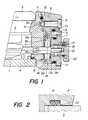
- Figure 1 is a partial view in axial section of this watch.
- Figure 2 is an enlarged view of a detail of the figure 1.
- the watch illustrated by this figure includes a movement 1 covered with an indicator dial 2, housed in a case comprising a middle part 3, a base 4 and a crystal 5.
- the upper part of the middle part 3 has a annular recess 6 in the bottom of which is formed a annular groove 7.
- a rotating bezel 8 is arranged in the annular recess 6 and is retained axially by pins 9a formed in the extension of the end screw 9, radially passing through the rotating bezel 8 and angularly distributed around it.
- These pegs 9a are engaged in an annular groove 10 on the face side of the annular recess 6.
- An annular groove 11 parallel to the annular groove 10 serves to receive a 0-ring seal 12.
- a second seal 13 is housed in a groove annular 23, formed in the underside of the telescope rotating 8.
- this seal 13 has a semi-circular section, its flat face being glued in the bottom of the groove 23.
- the shape of the seal 13 and the bonding thereof allow increase its service life and facilitate rotation of the rotating bezel 8 in both directions.
- the joint 12, as for it is preferably an O-ring seal.
- This rotating bezel 8 has another projecting annular part 8a at the end of which an edge teeth 8b is provided, this part annular 8a being housed in the annular groove 7.
- This groove 7 communicates with a cylindrical housing 14, whose axis of revolution coincides with the axis of the rod winder 15.
- This winding rod 15 has a square section 15a which crosses an opening of same section, centered on the axis of a pinion 16 meshing with teeth 8b.
- a closing member 17, carrying a tube 18 provided with a 0-ring seal 19 intended to cooperate with a winding crown 20 is fitted into the housing cylindrical 14 by two screws (not shown), fixed in the middle part 3 on either side of the winding stem 15. Therefore, the pinion 16 is axially fixed between two stops formed by the bottom of the cylindrical housing 14 on the one hand, and the internal face of the closing member 17.
- the lateral face of the latter has a groove 17a in which is housed a 0-ring seal 24.
- Spacers, 21, 22, for example nylon can be arranged on the side and other of this pinion 16 to avoid seizing. Thanks to this arrangement, the square section section 15a of the winding stem 15 can slide freely through the opening of the pinion 16 and it remains in engagement with the toothing 8b of the rotating bezel. Therefore, the rod of winder 15 can occupy different positions, two or three for winding, setting the time, or even setting the date, like a normal winding stem, the binding kinematics remaining constantly established between the telescope rotating 8 and the winding stem 15, via pinion 16 integral in rotation with this rod 15 thanks to section 15a of square section.
- winding mechanism and time setting is fully protected against infiltration water and dust through seals, thus protecting this mechanism from deterioration or seizure of moving parts rotating bezel 8 and pinion 16.
Description
Claims (7)
- Montre comprenant un boítier muni d'une lunette tournante (8) dont une partie annulaire (8a) est dentée (8b), une tige de remontoir (15) présentant un tronçon de section polygonale (15a) situé à l'extérieur du mouvement de la montre, un pignon (16) muni d'une ouverture de section complémentaire à celle dudit tronçon (15a), engagé sur celui-ci, la denture du pignon (16) étant en prise avec celle de ladite partie annulaire dentée (8b), formant une liaison cinématique entre la lunette tournante (8) et la tige de remontoir (15), caractérisée par le fait que ledit pignon (16) est positionné axialement entre deux butées solidaires du boítier, ledit tronçon de section polygonale (15a) de la tige de remontoir (15) présentant une longueur choisie pour permettre de déplacer axialement ladite tige de remontoir (15) entre au moins deux positions, l'une de remontage et l'autre de mise à l'heure, tout en maintenant la liaison cinématique entre la lunette (8) et la tige de remontoir (15) par l'intermédiaire dudit pignon (16).
- Montre selon la revendication 1, caractérisée par le fait que ladite partie annulaire dentée (8a) est constituée par une partie faisant saillie sous la lunette tournante (8) et présentant une denture de chant (8b), cette partie annulaire saillante (8a) s'étendant dans une rainure annulaire (7) de la carrure (3).
- Montre selon la revendication 2, caractérisée par le fait que ledit pignon (16) est disposé dans un logement (14) s'ouvrant sur la face latérale externe de la carrure (3), communiquant avec ladite rainure annulaire (7) de la carrure (3) et qu'il est maintenu par un organe de fermeture (17) fixé à la carrure (3).
- Montre selon la revendication 1, caractérisée par le fait que la lunette tournante (8) est retenue axialement sur la carrure (3) par des vis (9) la traversant radialement et dont les extrémités sont engagées dans une rainure annulaire (10) de la face latérale de la carrure (3).
- Montre selon la revendication 3, caractérisée par le fait que des joints d'étanchéité (12, 13, 19, 23) isolent le mécanisme de remontage et de mise à l'heure du milieu environnant.
- Montre selon la revendication 1, caractérisé par le fait qu'au moins un joint annulaire de section semi-circulaire (12, 13) est disposé entre la lunette tournante (8) et la carrure (3), la face plane de ce joint étant collée.
- Montre selon l'une des revendications précédentes, caractérisée par le fait que le ressort moteur est un ressort du type à bride glissante.
Applications Claiming Priority (4)
| Application Number | Priority Date | Filing Date | Title |
|---|---|---|---|
| CH931/96 | 1996-04-12 | ||
| CH93196 | 1996-04-12 | ||
| CH93196 | 1996-04-12 | ||
| PCT/IB1997/000380 WO1997039386A1 (fr) | 1996-04-12 | 1997-04-10 | Montre |
Publications (2)
| Publication Number | Publication Date |
|---|---|
| EP0892944A1 EP0892944A1 (fr) | 1999-01-27 |
| EP0892944B1 true EP0892944B1 (fr) | 2000-01-12 |
Family
ID=4198502
Family Applications (1)
| Application Number | Title | Priority Date | Filing Date |
|---|---|---|---|
| EP97914510A Expired - Lifetime EP0892944B1 (fr) | 1996-04-12 | 1997-04-10 | Montre |
Country Status (8)
| Country | Link |
|---|---|
| EP (1) | EP0892944B1 (fr) |
| JP (1) | JP2000508764A (fr) |
| CN (1) | CN1138190C (fr) |
| AU (1) | AU2174297A (fr) |
| DE (1) | DE69701136T2 (fr) |
| HK (1) | HK1021416A1 (fr) |
| TW (1) | TW340200B (fr) |
| WO (1) | WO1997039386A1 (fr) |
Families Citing this family (10)
| Publication number | Priority date | Publication date | Assignee | Title |
|---|---|---|---|---|
| JP2007085895A (ja) * | 2005-09-22 | 2007-04-05 | Seiko Epson Corp | 携帯機器 |
| US7350968B2 (en) * | 2006-07-14 | 2008-04-01 | Alexander Meerovitsch | Case for a watch movement |
| JP4878339B2 (ja) * | 2007-08-08 | 2012-02-15 | セイコーインスツル株式会社 | 時計 |
| DE202008007744U1 (de) | 2008-04-08 | 2009-03-19 | Dugi, Zelimir, Dipl.-Ing. | Armbanduhr |
| ITMI20100431A1 (it) * | 2010-03-17 | 2011-09-18 | Carlo Musso | Orologio da polso meccanico, manuale o automatico privo di bottone di carica |
| CH709202B1 (fr) * | 2014-01-17 | 2020-01-15 | Giorgio Bulgari Sa | Montre comprenant un dispositif de recharge d'une unité de fourniture d'énergie électrique. |
| JP6741397B2 (ja) | 2014-02-10 | 2020-08-19 | ロレックス・ソシエテ・アノニムRolex Sa | 携帯時計側及び時計 |
| CN103926824B (zh) * | 2014-03-11 | 2018-10-23 | 东莞市珀丞精密制造科技有限公司 | 一种手表调时器 |
| US9360841B1 (en) * | 2015-11-23 | 2016-06-07 | Vishal Tolani | Watch with a time-setting bezel and shaft connection |
| CN106371305B (zh) * | 2016-10-27 | 2018-12-25 | 深圳市飞亚达精密计时制造有限公司 | 一种利用前圈上条的手表结构 |
Family Cites Families (8)
| Publication number | Priority date | Publication date | Assignee | Title |
|---|---|---|---|---|
| CH65378A (fr) * | 1913-07-10 | 1914-06-16 | Fabrieque D Horlogerie Octo Eu | Mécanisme de remontage et de mise à l'heure aux montres pour automobiles et autres véhicules |
| FR21674E (fr) * | 1914-05-08 | 1921-01-11 | Edouard Seignol | Système de commande du remontoir et de la remise à l'heure dans les montres par une couronne dont l'axe est perpendiculaire au plan du cadran |
| CH316834A (fr) * | 1954-10-29 | 1956-10-31 | Simon John | Boîte de montre |
| CH473411A (fr) * | 1964-06-18 | 1969-07-15 | Nerfos S A R L | Ensemble comprenant un barillet, un ressort-moteur et une bride de surtension, pour montre à remontage automatique |
| CH516833A (fr) * | 1969-07-29 | 1971-08-31 | Piquerez Sa Ervin | Montre munie d'une lunette tournante extérieure |
| CH632890B (fr) * | 1979-08-08 | Gen Watch Co Ltd | Procede de fabrication d'une boite de montre et boite de montre obtenue par ce procede. | |
| US4626107A (en) * | 1984-10-01 | 1986-12-02 | Citizen Watch Co., Ltd. | Structure of rotating mechanism for watch case |
| CH684620B5 (fr) * | 1993-01-29 | 1995-05-15 | Walter Schlup | Mouvement d'horlogerie comportant deux affichages analogiques opposés. |
-
1997
- 1997-04-10 DE DE69701136T patent/DE69701136T2/de not_active Expired - Lifetime
- 1997-04-10 CN CNB971936560A patent/CN1138190C/zh not_active Expired - Fee Related
- 1997-04-10 EP EP97914510A patent/EP0892944B1/fr not_active Expired - Lifetime
- 1997-04-10 WO PCT/IB1997/000380 patent/WO1997039386A1/fr active IP Right Grant
- 1997-04-10 AU AU21742/97A patent/AU2174297A/en not_active Abandoned
- 1997-04-10 TW TW086104596A patent/TW340200B/zh not_active IP Right Cessation
- 1997-04-10 JP JP9536903A patent/JP2000508764A/ja active Pending
-
1999
- 1999-06-17 HK HK99102606A patent/HK1021416A1/xx not_active IP Right Cessation
Also Published As
| Publication number | Publication date |
|---|---|
| DE69701136D1 (de) | 2000-02-17 |
| EP0892944A1 (fr) | 1999-01-27 |
| CN1138190C (zh) | 2004-02-11 |
| TW340200B (en) | 1998-09-11 |
| JP2000508764A (ja) | 2000-07-11 |
| WO1997039386A1 (fr) | 1997-10-23 |
| DE69701136T2 (de) | 2000-09-21 |
| HK1021416A1 (en) | 2000-06-09 |
| CN1215483A (zh) | 1999-04-28 |
| AU2174297A (en) | 1997-11-07 |
Similar Documents
| Publication | Publication Date | Title |
|---|---|---|
| EP2945026B1 (fr) | Mécanisme de correction rapide d'horlogerie | |
| EP0892944B1 (fr) | Montre | |
| EP1857892A1 (fr) | Montre à élément tournant | |
| EP1862871B1 (fr) | Pièce d'horlogerie comportant un dispositif de mise à l'heure amélioré | |
| EP1513030A1 (fr) | Pièce d'horlogerie comprenant deux boítes susceptibles de pivoter l'une par rapport à l'autre | |
| EP1152303A1 (fr) | Montre à mécanisme de remontage et de correction d'au moins deux organes indicateurs | |
| EP1544691A1 (fr) | Pièce d'horlogerie dont l'aiguille des heures peut être avancée ou reculée par pas d'une heure | |
| EP1139182B1 (fr) | Mécanisme indicateur de réserve de marche et montre munie d'un tel mécanisme | |
| EP1978420A1 (fr) | Dispositif de correction d'un mécanisme d'affichage pour pièce d'horlogerie et roue équipant un tel dispositif | |
| CH691632A5 (fr) | Montre à tige de remontoir et de mise à l'heure en deux parties. | |
| EP0531895A1 (fr) | Dispositif de correction unidirectionnel d'un organe d'affichage horaire | |
| EP2010972B1 (fr) | Piece d'horlogerie comportant un mecanisme de mise a l'heure commande par une lunette tournante | |
| EP0668551B1 (fr) | Montre à double faces | |
| CH501259A (fr) | Pièce d'horlogerie | |
| EP1566708B1 (fr) | Dispositif de remontoir | |
| CH707555A2 (fr) | Mécanisme de transmission de mouvements axiaux et rotatifs entre deux axes décalés et pièce d'horlogerie comportant ce mécanisme. | |
| EP2600214B1 (fr) | Mécanisme de transmission entre deux parties d'une tige de commande pour mouvement horloger | |
| CH717111B1 (fr) | Mécanisme de correction d'affichage et mouvement horloger comportant ce mécanisme. | |
| EP1288743A1 (fr) | Dispositif d'embrayage pour pièce d'horlogerie | |
| EP4312083A1 (fr) | Dispositif d'embrayage-débrayage pour piece d'horlogerie | |
| CH717211A2 (fr) | Couronne pour boîte de pièce d'horlogerie, tige pour mouvement horloger et pièce d'horlogerie. | |
| FR2463435A1 (fr) | Dispositif de remise a l'heure rapide d'une montre | |
| CH718740B1 (fr) | Aiguille d'affichage flexible et mécanisme d'actionnement d'une telle aiguille d'affichage. | |
| EP1045298A2 (fr) | Remontoir situé sur le fond de la montre | |
| FR2492999A1 (fr) | Dispositif mecanique de mise a l'heure d'une montre a affichage analogique |
Legal Events
| Date | Code | Title | Description |
|---|---|---|---|
| PUAI | Public reference made under article 153(3) epc to a published international application that has entered the european phase |
Free format text: ORIGINAL CODE: 0009012 |
|
| 17P | Request for examination filed |
Effective date: 19981008 |
|
| AK | Designated contracting states |
Kind code of ref document: A1 Designated state(s): CH DE GB IT LI |
|
| GRAG | Despatch of communication of intention to grant |
Free format text: ORIGINAL CODE: EPIDOS AGRA |
|
| GRAG | Despatch of communication of intention to grant |
Free format text: ORIGINAL CODE: EPIDOS AGRA |
|
| GRAH | Despatch of communication of intention to grant a patent |
Free format text: ORIGINAL CODE: EPIDOS IGRA |
|
| 17Q | First examination report despatched |
Effective date: 19990527 |
|
| GRAH | Despatch of communication of intention to grant a patent |
Free format text: ORIGINAL CODE: EPIDOS IGRA |
|
| GRAA | (expected) grant |
Free format text: ORIGINAL CODE: 0009210 |
|
| AK | Designated contracting states |
Kind code of ref document: B1 Designated state(s): CH DE GB IT LI |
|
| REG | Reference to a national code |
Ref country code: CH Ref legal event code: EP |
|
| REF | Corresponds to: |
Ref document number: 69701136 Country of ref document: DE Date of ref document: 20000217 |
|
| REG | Reference to a national code |
Ref country code: CH Ref legal event code: NV Representative=s name: MOINAS SAVOYE & CRONIN |
|
| ITF | It: translation for a ep patent filed |
Owner name: SOCIETA' ITALIANA BREVETTI S.P.A. |
|
| GBT | Gb: translation of ep patent filed (gb section 77(6)(a)/1977) |
Effective date: 20000320 |
|
| PLBE | No opposition filed within time limit |
Free format text: ORIGINAL CODE: 0009261 |
|
| STAA | Information on the status of an ep patent application or granted ep patent |
Free format text: STATUS: NO OPPOSITION FILED WITHIN TIME LIMIT |
|
| 26N | No opposition filed | ||
| REG | Reference to a national code |
Ref country code: GB Ref legal event code: IF02 |
|
| PGFP | Annual fee paid to national office [announced via postgrant information from national office to epo] |
Ref country code: GB Payment date: 20140422 Year of fee payment: 18 |
|
| PGFP | Annual fee paid to national office [announced via postgrant information from national office to epo] |
Ref country code: IT Payment date: 20140417 Year of fee payment: 18 Ref country code: DE Payment date: 20140411 Year of fee payment: 18 |
|
| PGFP | Annual fee paid to national office [announced via postgrant information from national office to epo] |
Ref country code: CH Payment date: 20150407 Year of fee payment: 19 |
|
| REG | Reference to a national code |
Ref country code: DE Ref legal event code: R119 Ref document number: 69701136 Country of ref document: DE |
|
| GBPC | Gb: european patent ceased through non-payment of renewal fee |
Effective date: 20150410 |
|
| PG25 | Lapsed in a contracting state [announced via postgrant information from national office to epo] |
Ref country code: GB Free format text: LAPSE BECAUSE OF NON-PAYMENT OF DUE FEES Effective date: 20150410 Ref country code: DE Free format text: LAPSE BECAUSE OF NON-PAYMENT OF DUE FEES Effective date: 20151103 Ref country code: IT Free format text: LAPSE BECAUSE OF NON-PAYMENT OF DUE FEES Effective date: 20150410 |
|
| REG | Reference to a national code |
Ref country code: CH Ref legal event code: PL |
|
| PG25 | Lapsed in a contracting state [announced via postgrant information from national office to epo] |
Ref country code: CH Free format text: LAPSE BECAUSE OF NON-PAYMENT OF DUE FEES Effective date: 20160430 Ref country code: LI Free format text: LAPSE BECAUSE OF NON-PAYMENT OF DUE FEES Effective date: 20160430 |