EP0892512A2 - Kreis- und Kanalzuteilungsplan für optische Übertragungen - Google Patents
Kreis- und Kanalzuteilungsplan für optische Übertragungen Download PDFInfo
- Publication number
- EP0892512A2 EP0892512A2 EP98305371A EP98305371A EP0892512A2 EP 0892512 A2 EP0892512 A2 EP 0892512A2 EP 98305371 A EP98305371 A EP 98305371A EP 98305371 A EP98305371 A EP 98305371A EP 0892512 A2 EP0892512 A2 EP 0892512A2
- Authority
- EP
- European Patent Office
- Prior art keywords
- link
- channels
- optical
- filter
- channel
- Prior art date
- Legal status (The legal status is an assumption and is not a legal conclusion. Google has not performed a legal analysis and makes no representation as to the accuracy of the status listed.)
- Withdrawn
Links
Images


Classifications
-
- H—ELECTRICITY
- H04—ELECTRIC COMMUNICATION TECHNIQUE
- H04B—TRANSMISSION
- H04B10/00—Transmission systems employing electromagnetic waves other than radio-waves, e.g. infrared, visible or ultraviolet light, or employing corpuscular radiation, e.g. quantum communication
- H04B10/29—Repeaters
- H04B10/291—Repeaters in which processing or amplification is carried out without conversion of the main signal from optical form
- H04B10/297—Bidirectional amplification
- H04B10/2972—Each direction being amplified separately
-
- H—ELECTRICITY
- H04—ELECTRIC COMMUNICATION TECHNIQUE
- H04B—TRANSMISSION
- H04B10/00—Transmission systems employing electromagnetic waves other than radio-waves, e.g. infrared, visible or ultraviolet light, or employing corpuscular radiation, e.g. quantum communication
- H04B10/25—Arrangements specific to fibre transmission
- H04B10/2507—Arrangements specific to fibre transmission for the reduction or elimination of distortion or dispersion
- H04B10/2543—Arrangements specific to fibre transmission for the reduction or elimination of distortion or dispersion due to fibre non-linearities, e.g. Kerr effect
- H04B10/2563—Four-wave mixing [FWM]
Definitions
- This invention relates, in general, to an optical transmission plan and optical amplifier circuit therefor, and is particularly, but not exclusively, applicable to a bi-directional wave division multiplexed (WDM) amplifier circuit and a channel assignment plan for optical transmissions therein.
- WDM wave division multiplexed
- WDM wavelength division multiplexed
- optical amplifier designs have been optimised for WDM operation.
- WDM wavelength division multiplexed
- all the WDM channels will be transmitted through the transmission fibre in the same direction
- bi-directional transmission configuration has some channels within the fibre travelling in one direction and other channels travelling in an opposite direction.
- This latter system configuration offers a number of advantages, especially in relation to the number of redundant transmission terminals required for reliability.
- optical amplified designs are currently being optimised for bi-directional transmission.
- bi-directional transmission are optimised by splitting the available channels into distinct operating bands, one for each direction. These bands are sometimes referred to as the 'blue' and 'red' bands, and can contain varying numbers of channels.
- the blue band may have channels based within a wavelength range of 1527 to 1540 nanometres (nm)
- the red band may have channels based within a wavelength range of 1545nm to 1560nm.
- Each channel supports information transfer through the modulation of data onto a carrier frequency (generated by a laser).
- typical modulation techniques include amplitude and phase modulation, and frequency shift keying (FSK).
- WDM channel allocation is typically based on the International Telecommunications Union (ITU) standardised wavelength grid, and is therefore subject to specified minimum channel spacing.
- ITU International Telecommunications Union
- the present ITU standard requires a channel spacing of 100 GigaHertz (GHz), with possible channel combinations using multiples of this 100 GHz channel spacing.
- GHz GigaHertz
- each band can support sixteen channels having a 100 GHz spacing regime, i.e. thirty-two channels in total.
- each channel suffers from higher levels of performance degradation due to multi-channel operation. Specifically, the superposition of harmonics results in significant detrimental effects on data integrity within a specific channel. More particularly, in an optical transmission system, densely packed channels exhibit an intermodulation product, known as "four-wave mixing". Basically, the degradation from the intermodulation product arises from sidebands being superpositioned on or about adjacent optical channels, with each sideband generated as a consequence of the spacing between adjacent channels. Increasing the channel separation therefore improves transmitted signal integrity, but this improved performance only results from sacrificing overall transmission capacity.
- One way to maintain the same total number of channels in a bi-directional amplifier, whilst reducing the channel degradation arising from an intermodulation product is to adopt an interleaved channel plan in which adjacent channels propagate in opposite directions. In practice, this means that the channel spacing between adjacent channels in one direction has been doubled, with the effects on adjacent co-propagating channels accordingly reduced.
- An additional advantage of this scheme arises from the distribution of the "dead band" in which channels cannot be used. Specifically, in relation to a dual band system in which distinct bands are allocated for up-link and down-link transmissions, it is imperative that the bands be separated, (isolated) to prevent corruption of data.
- any attenuated system (as implemented within a filter, for example) isolation is dependent on operating parameters of the actual attenuation devices.
- the filters In the specific case of filters in an optical system, the filters have a response curve that gradually rises and gradually tails off. Consequently, a minimum extinction zone must exist between the separate channel bands, with the width of the extinction zone necessarily excluding any overlap potentially arising from the lead-in or tail-off profiles of the filter response characteristics.
- the rate of increase of attenuation against wavelength (termed "roll-off') that is achievable between the channel bands through filtering produces a portion of the bandwidth that cannot be used for communication information; this is the overlapping region of the "dead band”.
- the channel spacing in one direction is doubled and so the filter edges are steep enough not to lose a channel slot due to dead bands.
- the dead band is distributed across the whole of the operating bandwidth, and so the optical system is able to increase the total number of available channels.
- EP-A-0 680 168 describes a system and method for optimising spectral efficiency using time-frequency-code slicing. More particularly, through the scheduling of the various speed users within the frequency and time domains, the system and method allocates and makes use of the available spectrum.
- EP-A-0 668 675 describes a multi-channel optical fibre communication system in which wavelength division multiplexed channels have simple channel-to-channel spacing which prevent substantial coincidence of 4-wave mixing products with channel carriers.
- US patent 5,390,043 describes an optical heterodyne communication system for transmission of multiple optical channels at different wavelengths, with the optical channels grouped into blocks. Spacing between optical channels with a block is equal to or somewhat greater than the channel bandwidth, while the spacing between blocks is such that when the optical signal is heterodyned with a local oscillator lightwave the interference with a selected optical channel from the adjacent block does not exceed a predetermined level.
- a method of assigning a band of optical channels to an optical fibre arranged to support bi-directional communication in an up-link and a down-link, the band of optical channels having adjacent wavelengths the method arranged to reduce intermodulation in each of the up-link and down-link by assigning to at least one of the up-link and the down-link at least one pair of channels having adjacent wavelengths in the band of optical channels, wherein assignment of channels to the up-link and down-link are mutually exclusive and each of the up-link and the down-link comprises at least one other optical channel having a wavelength not adjacent to said at least one pair of channels.
- the optical channels in the up-link and down-link are separated by no more that two contiguous optical channels.
- at least one of the up-link and the down-link comprises at least two pairs of adjacent optical channels, the at least two pairs being separated by no more than two adjacent channels.
- an optical fibre supporting bi-directional communication on a multiplicity of optical channels having adjacent wavelengths the multiplicity of optical channels distributed between an up-link and a down-link
- the optical fibre characterised in that is supports at least one pair of channels having adjacent wavelengths in at least one of the up-link and the down-link, wherein channels assigned to the up-link and down-link are mutually exclusive and each of the up-link and the down-link comprises at least one other optical channel having a wavelength not adjacent to said at least one pair of channels, whereby four-wave mixing in each of the up-link and down-link is reduced.
- the optical fibre may, in fact, be one of a plurality of similar optical fibres of an optical communication system.
- a method of bi-directional transfer of data through an optical fibre the data conveyed in up-link and down-link directions in the optical fibre in a multiplicity of optical channels having adjacent wavelengths, the multiplicity of optical channels distributed between the up-link and the down-link directions, the method characterised by the steps of: assigning at least one pair of channels having adjacent wavelengths to at least one of the up-link and the down-link, wherein channels assigned to the up-link and down-link directions are mutually exclusive and each of the up-link and the down-link directions comprises at least one other optical channel having a wavelength not adjacent to said at least one pair of channels, whereby four-wave mixing in each of the up-link and down-link directions is reduced; and modulating channels to support simultaneous transfer of the data in the up-link and down-link directions.
- a circuit responsive to a broadband optical signal supporting a plurality of channels comprising: a directional coupler arranged to receive the broadband optical signals and configured to provide an output signal; a filter, responsive to the output signal, having a characteristic arranged to isolate from the output signal at least one desired channel on at least one filtered output; and a reflector coupled to the at least one filtered output and arranged to reflect the at least one filtered output back into the filter such that the at least one filtered output is subjected to a second filtering process that improves isolation of the at least one desired channel.
- a method of isolating at least one desired optical channel from a broadband optical signal applied to a filter the broadband optical channel supporting a plurality of channels and the filter having a characteristic arranged to isolate the at least one desired channel: filtering the broadband optical signal to produce a filtered output signal containing the at least one desired channel; and re-filtering the filtered output signal in the filter to isolate further the at least one desired channel.
- an aspect of the present invention has identified several channel allocation schemes that generally reduce interference from that associated with a conventional single interleaved structure in which alternate (rather than adjacent) carrier frequencies are assigned to the up-link or down-link communication paths.
- the conventional interleaved structure is identified as scheme A in Table 1 below.
- channel number that are shown in italic underlining are all uni-directional channels and, as such, are each assigned (on a mutually exclusive basis) to either the up-link or down-link.
- channel numbers 1+2n are all assigned to the down-link
- channel numbers 2+2n are all assigned to the up-link.
- Table 1 is indicative of a sixteen channel system
- the patterns provided in relation to the channel allocation mechanisms of scheme B though scheme E can be extended or truncated to systems containing, respectively, more or fewer channels, as will be understood.
- the channels may be evenly spaced, but in all cases an increasing channel number is indicative of an increased wavelength of a channel carrier.
- the up-link and down-link are considered to contain the same numbers of channels, this need not be the case.
- the fibre design parameter lambda zero (l 0 ) is located beyond, i.e. at a longer wavelength, the largest channel number.
- the efficiency or effectiveness of four-wave mixing also depends upon a relative positioning of each channel in relation to l 0 , with reduced intermodulation products (from non-coherent combinations) occurring with a lengthening in distance away from l 0 ,
- schemes B, C, D and E of Table 1 it can be seen that their individual channel allocation schemes are arranged to produce a reduced four-wave mixing through the provision, in each of the up-link and down-link, of at least one pair of contiguous channels (from an available operating spectrum), with the channels in the up-link and down-link being mutually exclusive. Furthermore, in terms of the channel spacing, there is no more that a separation of two contiguous channels from a respective sequence of channels for either the up-link or down-link. Thirdly, there is a separation of at least two adjacent channels between adjacent contiguous pairs of directionally similar channels, perhaps best demonstrated in relation to schemes B and C of Table 1.
- the optical amplifier circuit 10 contains a circulator 12-14, a WDM splitter or another equivalent component that isolates and then routes incident signals in an identified directions only (hereinafter generically termed "directional couplers") at the respective inputs to the alternate transmission paths 16-18.
- directional couplers a WDM splitter or another equivalent component that isolates and then routes incident signals in an identified directions only
- the circulators 12-14 operate on a directional basis and provide separation of bi-directional signals whilst maintaining isolation between the bi-directional components of the incident data transmissions.
- the circulators 12-14 operate to direct communication traffic (supported on the optical channels) along a predefined path and therefore to prevent a first path 16, e.g. an up-link, from merging and interfering with a second path 18, e.g. a down-link, at a circuit juncture.
- the optical amplifier circuit 10 further includes a separate amplification module 20-22, typically having two amplification stages, for each direction 16-18.
- filters 24-26 must be included to attenuate unwanted optical channels associated with the directionally opposing transmission path.
- These filters 24-26 therefore necessarily operate in a selective bandpass mode, and typically take the form of a comb filter, or the like, that is arranged to eliminate undesired wavelengths (i.e. channels).
- the comb filter is arranged to screen out the carrier frequencies associated with every other channel.
- the combs on each filter 24-26 would have an inverse but complementary relation.
- the amplification functions are provided by broadband gain (amplification) blocks having Erbium window profiles, while the filters are constructed from components that allow light to propagate in a single direction, as will be readily appreciated.
- the filters are more typically realised by a multi-layer optical dielectric filter that exhibits local transmission/reflection properties, or waveguide devices or transmissive Bragg gratings.
- the filters 24-26 of FIG. 1 can, however, be located at a number of alternative positions in each transmission path 16-18 of the optical amplifier circuit 10. This is indicated in the diagram by the fact that the filters 24-26 are shown in dotted outline. Specifically, a filter can be positioned before the amplification module, between the amplification stages (perhaps at an intersection position), or after a second one of a pair of serially coupled amplification stages. Each different position does, however, effect the performance of the optical amplifier circuit in a different way. Specifically, if amplification occurs before the first amplification module, there is a direct impact on amplifier noise performance that arises from noise being amplified; this is clearly undesirable.
- the specification for the comb filter must take into account two limitations, namely the need to prevent oscillation in the region of overlap between the two combs and the extinction (isolation) required in the rejected channels to limit sufficiently the adverse effects of multi-path interference (usually considered to be ⁇ 50 decibels (dB) net round trip loss).
- FIG. 2 illustrates a typical profile 29 for an Erbium window that demonstrates how amplification (gain) varies with wavelength, I. Specifically, after a fairly rapid parabolic rise to a maximum gain at about 15% of the window, there is a parabolic drop off in gain until, at about 30%, a substantially uniform gain is achieved for a significant portion of the remaining Erbium window. Gain then tails off rapidly.
- FIG. 3 illustrates the oscillation and multi-path interference routes in the optical amplifier circuit of FIG. 1.
- FIG. 3 ostensibly corresponds to the structure previously described in relation to FIG. 1, although a pair of optical connectors 30-32 are coupled to circulators 12-14 and define an edge for the optical amplifier circuit 10.
- the pair of optical connectors 30-32 each typically exhibits a maximum reflection level between a transmission fibre and the optical amplifier circuit defined by the Bellcore standard, i.e. a level of -24dB. Consequently, assuming that an optical channel 34 is incident on a first one of the pair of optical connectors, e.g.
- the optical channel passes 34 through circulator 14, along transmission path 18, through a series combination of amplification module 22 and circulator 12 before being reflected by a second one of the pair 30 and back along transmission path 16.
- a reflected signal 36 originating from the optical channel 34 passes through circulator 12, a series combination of amplification module 20 and circulator 14 before undergoing a second refection 38 (back along transmission path 16) at the first one of the pair of optical connectors 30.
- Fig. 4 illustrates a filter characteristic that satisfies the operational requirements of a bi-directional WDM amplifier arrangement of a preferred embodiment of the present invention.
- the filter characteristic (a plot of loss against wavelength) is, however, illustrated in an exaggerated format. More particularly, two filter characteristics are actually shown and with their respective pass bands superimposed (one on the other) to illustrate the combined properties of the filter.
- a filter characteristic 40 for an up-link has a passband 42 corresponding to a stop-band for a second filter characteristic 44 for a down-link.
- First and second points of intersection 48-50 between the first filter characteristics 40 and the second filter characteristic 44 represent a most favourable position for oscillation (i.e.
- first level 52 corresponding to a difference in loss between the stop-band 46 of the second filter characteristic 44 and the point of intersection of the respective first and second filter characteristics.
- first level 52 has a considered to have a level of -5dB for stable operation.
- a second level 54 corresponding to the difference in loss between the stop-band 46 of the second filter and the passband of the first filter characteristic is associated with an isolation level required to address the effects of multi-path within the optical amplifier circuit.
- oscillation in an optical circuit comprised from reflectors and amplifiers is most likely to occur at a point of highest gain, i.e. corresponding to the points of intersection 48-50 of FIG. 4.
- the circular path (illustrated in FIG. 3) between reflectors acts as a cavity, whereby the circuit acts as a laser. Consequently, spurious power is distributed across the frequency spectrum causing disruption of data integrity.
- Multi-path interference arises from the destructive combination of identical signals that have travelled different paths through the optical circuit.
- a fibre-based Bragg grating 50 is illustrated in FIG. 5.
- the Bragg grating comprises a photosensitive optical fibre 52 that is arranged to receive incident optical signals 54.
- a series of high refractive index steps 56 may be equidistantly spaced (at a distance d) through the photosensitive optical fibre 52, although the Bragg grating may be chirped.
- These high index steps 56 are illuminated by a high intensity light beams, typically of an ultra-violet wavelength (e.g. ⁇ 200nm).
- the spacing between the index steps determines the reflective or transmissive properties of the grating, as will be understood.
- the multitude of index steps in the Bragg diffraction grating could be of the same width.
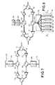
- a double pass of the filtering elements can be achieved by the circuit designs shown in FIG. 6 and FIG. 7.
- FIG. 6 an optical amplifier circuit is shown, which circuit is substantially similar to that previously described in relation to FIG. 1.
- elements in FIG. 6 that are common with FIG. 1 share common reference numerals.
- these filter are not now in series with the amplification modules 20-22, but instead are positioned relative to four-port circulators 60-62. More specifically, in each of the respective transmission paths 16 and 18, a serially coupled combination of a comb transmission filter 64-66 and a broadband mirror 68-70 tap the respective four-port circulators 60-62 and give a double pass through the filter.
- a signal (or channel) that is applied to an input of the four-port circulator from a particular transmission path is filtered through an appropriate comb transmission filter, reflected from the associated broadband mirror, filtered for a second time in the comb transmission filter to improve isolation, and then re-inserted into the transmission path by the four-port circulator.
- FIG. 6 can be modified to take on the appearance of FIG. 7.
- the four-port circulator serves as an extra circulator to the basic design of FIG. 1, which extra four-port circulator is inserted between distinct amplification stages of the respective up-link and down-link transmission paths.
- the amplification stages may be recognised by discrete circuit elements, which amplification stages may be separated by a considerable distance and, perhaps, be supported on different fibres. Routing of the signal through the four-port circulator is identical to the mechanism described in relation to FIG. 6.
- a WDM demultiplexer can be combined with a wavelength selective reflector to replace the comb transmission filters; this is shown in FIG. 8.
- each comb transmission filters 64-66 of FIG. 7 is replaced by a series combination of an array waveguide (AWG) WDM demodulator/modulator 80-82 and a reflector 84-86, such as implemented as a plurality of parallel fibre Bragg gratings 88-96.
- AMG array waveguide
- a broadband input 98-100 (provided by an appropriate circulator 60-62 and containing adjacent channels I 1 to I n ) to the WDM demodulator/modulator 80-82) is split into selected individual channels (based on wavelength), which individual channels are then applied to corresponding, wavelength dependent fibre Bragg gratings (or an equivalent form of reflector) for reflection back through the WDM demodulator/modulator 80-82.
- the selection of the individual channels in the corresponding AWG WDM 80-82 and their passages through the AWG WDM 80-82 provide the necessary levels of isolation.
- the multiplexer of the AWG WDM then acts to recombine the selected channels into a broadband signal that can be applied to a single fibre.
- filtering components have been shown to be in positions relative to the amplifier (for the purposes of explanation and illustration only). In each case, the filtering components could be before, half-way along or after each amplification module, as expressly detailed and shown in relation to FIG. 1.
- the present invention there advantageously provides a mechanism of assigning optical channels to reduce the effects of four-wave mixing, and realises an optical amplifier circuit that can isolate interleaved optical channels to an extent whereby a practical, bi-directional WDM amplifier can be manufactured at relatively low cost. Indeed, the mechanism of assignment is inherently applicable to bi-directional data transfer requiring modulation of a carrier in each channel.
- the filters of FIG. 6 and FIG. 7 could be implemented from waveguide devices, dielectric filters or transmissive Bragg gratings, but all of these are unable to meet the extinction specification in a single pass design and so a double pass of a comb shaped filter would be required, as described above.
- An alternative structure to the solitary transmissive Bragg grating or dielectric filter, would also be realised by a combination of a serial comb filter and a notch filter. Such a combination would increase the rejection of unwanted signals to a level sufficiently high or realise a bi-directional WDM amplifier.
- the capacity of an optical fibre could be sub-optimum by selectively leaving out channels and hence widening adjacent channel pair separation.
- the concept of having mutually exclusive pairs of channels assigned (on a sequential basis) to at least one of the up-link and the down-link is still applicable.
- the frequency separation between each pair of channels is preferably as small as possible to ensure optimal use of the limited bandwidth while avoiding adjacent channel interference.
Landscapes
- Physics & Mathematics (AREA)
- Electromagnetism (AREA)
- Engineering & Computer Science (AREA)
- Computer Networks & Wireless Communication (AREA)
- Signal Processing (AREA)
- Nonlinear Science (AREA)
- Optical Communication System (AREA)
Applications Claiming Priority (2)
| Application Number | Priority Date | Filing Date | Title |
|---|---|---|---|
| GB9715268 | 1997-07-18 | ||
| GB9715268A GB2327546A (en) | 1997-07-18 | 1997-07-18 | Optical frequency channel assignment plan and filtering technique to support it |
Publications (2)
| Publication Number | Publication Date |
|---|---|
| EP0892512A2 true EP0892512A2 (de) | 1999-01-20 |
| EP0892512A3 EP0892512A3 (de) | 2004-09-15 |
Family
ID=10816142
Family Applications (1)
| Application Number | Title | Priority Date | Filing Date |
|---|---|---|---|
| EP98305371A Withdrawn EP0892512A3 (de) | 1997-07-18 | 1998-07-06 | Kreis- und Kanalzuteilungsplan für optische Übertragungen |
Country Status (4)
| Country | Link |
|---|---|
| US (1) | US6751414B1 (de) |
| EP (1) | EP0892512A3 (de) |
| JP (1) | JPH11112427A (de) |
| GB (1) | GB2327546A (de) |
Cited By (5)
| Publication number | Priority date | Publication date | Assignee | Title |
|---|---|---|---|---|
| EP1004909A2 (de) * | 1998-11-28 | 2000-05-31 | Marconi Communications Limited | Photonisches System |
| EP1111818A2 (de) * | 1999-12-20 | 2001-06-27 | Nortel Networks Limited | Verfahren und Vorrichtung zum Ausgleichen der Leistung in einem optischen WDM Signal |
| EP1168686A1 (de) * | 2000-06-30 | 2002-01-02 | Lucent Technologies Inc. | Bidirektionale optische Übertragung mit zwei Kanalbanden |
| EP1248391A1 (de) * | 2001-04-04 | 2002-10-09 | Redfern Broadband Networks Inc. | Zweirichtungsverstärker |
| EP1584970A1 (de) * | 2004-03-22 | 2005-10-12 | Raytheon Company | Nicht-reziprokes optisches Bauelement mit getrennt regelbarer Einstellung der Übertragung in entgegengesetzte Richtungen |
Families Citing this family (15)
| Publication number | Priority date | Publication date | Assignee | Title |
|---|---|---|---|---|
| JP2002135212A (ja) * | 2000-10-20 | 2002-05-10 | Fujitsu Ltd | 双方向伝送可能な光波長分割多重伝送システム |
| KR100377199B1 (ko) * | 2000-10-27 | 2003-03-26 | 주식회사 케이티 | 파장가변 광신호 삽입/추출 장치 |
| AUPR316901A0 (en) * | 2001-02-16 | 2001-03-15 | Future Fibre Technologies Pty Ltd | Optic communication system |
| KR100378111B1 (ko) | 2001-04-02 | 2003-03-29 | 삼성전자주식회사 | 광증폭기 및 이를 이용한 양방향 파장분할 다중 광통신시스템 |
| US7346280B1 (en) * | 2002-03-15 | 2008-03-18 | Cisco Technology, Inc. | Bi-directional long haul/ultra long haul optical communication link |
| JP2005333311A (ja) * | 2004-05-19 | 2005-12-02 | Chugoku Electric Power Co Inc:The | 2心双方向通信網における事故回復方法 |
| WO2006069172A2 (en) * | 2004-12-21 | 2006-06-29 | Wave7 Optics, Inc. | System and method for operating a wideband return channel in a bi-directional optical communication system |
| US20070003283A1 (en) * | 2005-06-29 | 2007-01-04 | At&T Corp. | Dynamic allocation of bandwidth in a bidirectional optical transmission system |
| EP2333991B1 (de) * | 2009-12-11 | 2014-02-19 | Alcatel Lucent | Bidirektionaler optischer Verstärker |
| CN102237932B (zh) * | 2010-04-30 | 2016-07-06 | 中兴通讯股份有限公司 | 长距光放大装置、无源光网络和光信号传输方法 |
| US20150304036A1 (en) * | 2014-04-17 | 2015-10-22 | Nec Laboratories America, Inc. | Interleaved Bidirectional Sub-Nyquist Transmission with Overlapping Counter-Propagating Signal Spectral Bands |
| US10374742B2 (en) * | 2017-02-15 | 2019-08-06 | Finisar Corporation | Bidirectional optical communication with minimal guard band |
| WO2021086578A1 (en) | 2019-10-31 | 2021-05-06 | Ciena Corporation | Asymmetric direct detection of optical signals |
| EP3930228A1 (de) * | 2020-06-26 | 2021-12-29 | ADVA Optical Networking SE | Verfahren und vorrichtung zur verwaltung einer spektralen kapazität eines wellenlängenmultiplexsystems |
| US11432434B2 (en) | 2020-12-07 | 2022-08-30 | Ciena Corporation | Apparatus and method for modifying airflow of a network element |
Citations (3)
| Publication number | Priority date | Publication date | Assignee | Title |
|---|---|---|---|---|
| US5390043A (en) * | 1991-02-12 | 1995-02-14 | Gte Laboratories Incorporated | Compressed channel spacing for optical heterodyne communication systems |
| EP0682278A1 (de) * | 1994-05-13 | 1995-11-15 | BRITISH TELECOMMUNICATIONS public limited company | Optisches Filter |
| EP0753944A1 (de) * | 1995-07-14 | 1997-01-15 | PIRELLI CAVI S.p.A. | Anordnung zur Reduzierung von durch Vierwellenmischung verursachtem optischen Rauschen |
Family Cites Families (24)
| Publication number | Priority date | Publication date | Assignee | Title |
|---|---|---|---|---|
| US4556293A (en) * | 1983-05-02 | 1985-12-03 | The United States Of America As Represented By The Secretary Of The Navy | Broadband unpolarized light source |
| DE3686710T2 (de) * | 1985-06-24 | 1993-03-18 | American Telephone & Telegraph | Optische umordnungsanordnung. |
| US5295209A (en) * | 1991-03-12 | 1994-03-15 | General Instrument Corporation | Spontaneous emission source having high spectral density at a desired wavelength |
| JP3396270B2 (ja) * | 1993-08-10 | 2003-04-14 | 富士通株式会社 | 光分散補償方式 |
| GB2281670B (en) * | 1993-09-01 | 1998-01-28 | Northern Telecom Ltd | WDM optical communication system |
| CA2139957C (en) * | 1994-02-18 | 1999-02-09 | Andrew R. Chraplyvy | Multi-channel optical fiber communication system |
| US6018528A (en) * | 1994-04-28 | 2000-01-25 | At&T Corp | System and method for optimizing spectral efficiency using time-frequency-code slicing |
| JPH08110487A (ja) * | 1994-10-11 | 1996-04-30 | Koshin Kogaku:Kk | 波長可変フィルタ装置 |
| GB9423105D0 (en) * | 1994-11-16 | 1995-01-04 | Northern Telecom Ltd | Optical wave grating filter |
| US5541766A (en) * | 1994-11-30 | 1996-07-30 | At&T Corp. | Gain control for optically amplified systems |
| US5633741A (en) * | 1995-02-23 | 1997-05-27 | Lucent Technologies Inc. | Multichannel optical fiber communications |
| JP3323690B2 (ja) * | 1995-03-15 | 2002-09-09 | ケイディーディーアイ株式会社 | 光波長多重通信装置 |
| US6055081A (en) * | 1995-03-15 | 2000-04-25 | Sumitomo Electric Industries, Ltd. | Chromatic dispersion compensator and chromatic dispersion compensating optical communication system |
| FR2734648B1 (fr) * | 1995-05-24 | 1997-06-20 | Alcatel Nv | Source de longueurs d'onde multiples |
| FR2736480B1 (fr) * | 1995-07-05 | 1997-09-19 | France Telecom | Disposif de coloration de signaux optiques |
| EP0772264B1 (de) * | 1995-10-30 | 2003-05-07 | Nec Corporation | Verfahren zum Schutz gegen optische Überintensität und System zur Verwendung in einem mit seltenen Erden dotierten Faserschaltkreis |
| US5742416A (en) * | 1996-03-28 | 1998-04-21 | Ciena Corp. | Bidirectional WDM optical communication systems with bidirectional optical amplifiers |
| US5912751A (en) * | 1996-05-28 | 1999-06-15 | Lucent Technologies Inc. | Fiber optic network using space and wavelength multiplexed data channel arrays |
| US5801858A (en) * | 1996-06-25 | 1998-09-01 | Northern Telecom Limited | Optical transmission systems using optical amplifiers and wavelength division multiplexing |
| KR100205052B1 (ko) * | 1996-07-12 | 1999-06-15 | 정선종 | 파장 가변형 모드록킹 광섬유 레이저 |
| US6049417A (en) * | 1997-06-02 | 2000-04-11 | Lucent Technologies Inc. | Wide band optical amplifier |
| US6081368A (en) * | 1997-12-23 | 2000-06-27 | Lucent Technologies Inc. | Optical amplifier for bi-directional WDM optical communications systems |
| US6043914A (en) * | 1998-06-29 | 2000-03-28 | Mci Communications Corporation | Dense WDM in the 1310 nm band |
| US6118563A (en) * | 1998-03-25 | 2000-09-12 | Corning Incorporated | Methods and apparatus for reducing four-wave mixing |
-
1997
- 1997-07-18 GB GB9715268A patent/GB2327546A/en not_active Withdrawn
-
1998
- 1998-07-06 EP EP98305371A patent/EP0892512A3/de not_active Withdrawn
- 1998-07-07 US US09/111,490 patent/US6751414B1/en not_active Expired - Lifetime
- 1998-07-21 JP JP10205015A patent/JPH11112427A/ja active Pending
Patent Citations (3)
| Publication number | Priority date | Publication date | Assignee | Title |
|---|---|---|---|---|
| US5390043A (en) * | 1991-02-12 | 1995-02-14 | Gte Laboratories Incorporated | Compressed channel spacing for optical heterodyne communication systems |
| EP0682278A1 (de) * | 1994-05-13 | 1995-11-15 | BRITISH TELECOMMUNICATIONS public limited company | Optisches Filter |
| EP0753944A1 (de) * | 1995-07-14 | 1997-01-15 | PIRELLI CAVI S.p.A. | Anordnung zur Reduzierung von durch Vierwellenmischung verursachtem optischen Rauschen |
Non-Patent Citations (2)
| Title |
|---|
| FORGHIERI F ET AL: "REDUCTION OF FOUR-WAVE MIXING CROSSTALK IN WDM SYSTEMS USING UNEQUALLY SPACED CHANNELS" IEEE PHOTONICS TECHNOLOGY LETTERS, IEEE INC. NEW YORK, US, vol. 6, no. 6, 1 June 1994 (1994-06-01), pages 754-756, XP000457239 ISSN: 1041-1135 * |
| TAGA H: "LONG DISTANCE TRANSMISSION EXPERIMENTS USING THE WDM TECHNOLOGY" JOURNAL OF LIGHTWAVE TECHNOLOGY, IEEE. NEW YORK, US, vol. 14, no. 6, 1 June 1996 (1996-06-01), pages 1287-1298, XP000598533 ISSN: 0733-8724 * |
Cited By (8)
| Publication number | Priority date | Publication date | Assignee | Title |
|---|---|---|---|---|
| EP1004909A2 (de) * | 1998-11-28 | 2000-05-31 | Marconi Communications Limited | Photonisches System |
| EP1004909A3 (de) * | 1998-11-28 | 2004-05-06 | Marconi UK Intellectual Property Ltd | Photonisches System |
| EP1111818A2 (de) * | 1999-12-20 | 2001-06-27 | Nortel Networks Limited | Verfahren und Vorrichtung zum Ausgleichen der Leistung in einem optischen WDM Signal |
| EP1111818B1 (de) * | 1999-12-20 | 2009-07-08 | Nortel Networks Limited | Verfahren zum Ausgleichen der Leistung in einem optischen WDM Signal |
| EP1168686A1 (de) * | 2000-06-30 | 2002-01-02 | Lucent Technologies Inc. | Bidirektionale optische Übertragung mit zwei Kanalbanden |
| US6973268B1 (en) | 2000-06-30 | 2005-12-06 | Lucent Technologies Inc. | Bi-directional optical transmission using dual channel bands |
| EP1248391A1 (de) * | 2001-04-04 | 2002-10-09 | Redfern Broadband Networks Inc. | Zweirichtungsverstärker |
| EP1584970A1 (de) * | 2004-03-22 | 2005-10-12 | Raytheon Company | Nicht-reziprokes optisches Bauelement mit getrennt regelbarer Einstellung der Übertragung in entgegengesetzte Richtungen |
Also Published As
| Publication number | Publication date |
|---|---|
| EP0892512A3 (de) | 2004-09-15 |
| GB2327546A (en) | 1999-01-27 |
| JPH11112427A (ja) | 1999-04-23 |
| GB9715268D0 (en) | 1997-09-24 |
| US6751414B1 (en) | 2004-06-15 |
Similar Documents
| Publication | Publication Date | Title |
|---|---|---|
| US6751414B1 (en) | Circuit and channel assignment plan for optical transmissions | |
| US5982518A (en) | Optical add-drop multiplexers compatible with very dense WDM optical communication systems | |
| GB2281670A (en) | WDM Optical communication system | |
| US6348984B1 (en) | Optical add/drop multiplexer | |
| US6512864B1 (en) | Optical multiplexer/demultiplexer arrangement for WDM signals having in-band and out-of-band signal components | |
| EP1088417B1 (de) | Verfahren und vorrichtung zur abzweigung von optischen kanälen in einem optischen übertragungssystem | |
| EP1033841B1 (de) | Rekonfigurierbarer Add/drop-Multiplexer für Faserkommunikationssysteme | |
| US6559988B1 (en) | Optical wavelength add/drop multiplexer for dual signal transmission rates | |
| US6388783B1 (en) | Narrow band wavelength division multiplexer and method of multiplexing optical signals | |
| US6650809B2 (en) | Multiple band optical multiplexer and demultiplexer | |
| US6516112B1 (en) | Optical wavelength filter and demultiplexer | |
| US6205269B1 (en) | Optical add/drop multiplexer | |
| WO2005109714A1 (en) | All-optical signal regeneration | |
| EP0862071B1 (de) | Optische Verzweigungsanordnung und optische Übertragungsmethode | |
| CA2400054A1 (en) | Methods and apparatus for preventing deadbands in an optical communication system | |
| EP1004045A1 (de) | Optischer wellenlängenmultiplexer | |
| US6671430B2 (en) | Optical device, terminal apparatus, and system for wavelength division multiplexing | |
| US6549701B1 (en) | Selectable wavelength channel filter for optical WDM systems | |
| US6546167B1 (en) | Tunable grating optical device | |
| US6665470B2 (en) | Optical filter | |
| EP0953854A1 (de) | Ringkoppler für optische Netzwerk | |
| JPH1172756A (ja) | 光信号波形劣化補償装置 | |
| JP2600507B2 (ja) | 光合分波器 | |
| Capmany et al. | WDM-SSB generation and dispersion mitigation in radio over fiber systems with improved performance using an AWG multiplexer with flat top resonances | |
| JP3562610B2 (ja) | 光周波数アッド・ドロップ回路およびそれを用いた光周波数多重ネットワーク |
Legal Events
| Date | Code | Title | Description |
|---|---|---|---|
| PUAI | Public reference made under article 153(3) epc to a published international application that has entered the european phase |
Free format text: ORIGINAL CODE: 0009012 |
|
| AK | Designated contracting states |
Kind code of ref document: A2 Designated state(s): AT BE CH CY DE DK ES FI FR GB GR IE IT LI LU MC NL PT SE |
|
| AX | Request for extension of the european patent |
Free format text: AL;LT;LV;MK;RO;SI |
|
| RIN1 | Information on inventor provided before grant (corrected) |
Inventor name: O'SULLIVAN, MAURICE Inventor name: KEYS, ROBERT Inventor name: JONES, KEVAN Inventor name: JOLLEY, NIGEL EDWARD Inventor name: DAVIES, FIONA |
|
| RAP3 | Party data changed (applicant data changed or rights of an application transferred) |
Owner name: NORTEL NETWORKS CORPORATION |
|
| RAP1 | Party data changed (applicant data changed or rights of an application transferred) |
Owner name: NORTEL NETWORKS LIMITED |
|
| RAP1 | Party data changed (applicant data changed or rights of an application transferred) |
Owner name: NORTEL NETWORKS LIMITED |
|
| RIC1 | Information provided on ipc code assigned before grant |
Ipc: 7H 04B 10/17 B Ipc: 7H 04J 14/02 B Ipc: 7H 04B 10/24 A |
|
| PUAL | Search report despatched |
Free format text: ORIGINAL CODE: 0009013 |
|
| RIC1 | Information provided on ipc code assigned before grant |
Ipc: 7H 04B 10/24 A |
|
| AK | Designated contracting states |
Kind code of ref document: A3 Designated state(s): AT BE CH CY DE DK ES FI FR GB GR IE IT LI LU MC NL PT SE |
|
| AX | Request for extension of the european patent |
Extension state: AL LT LV MK RO SI |
|
| 17P | Request for examination filed |
Effective date: 20050315 |
|
| AKX | Designation fees paid |
Designated state(s): DE FR GB |
|
| 17Q | First examination report despatched |
Effective date: 20050503 |
|
| STAA | Information on the status of an ep patent application or granted ep patent |
Free format text: STATUS: THE APPLICATION IS DEEMED TO BE WITHDRAWN |
|
| 18D | Application deemed to be withdrawn |
Effective date: 20050914 |