EP0892241A2 - Wuchtgeschoss mit mehrfachen Schlagwirkungssegmenten - Google Patents
Wuchtgeschoss mit mehrfachen Schlagwirkungssegmenten Download PDFInfo
- Publication number
- EP0892241A2 EP0892241A2 EP98250179A EP98250179A EP0892241A2 EP 0892241 A2 EP0892241 A2 EP 0892241A2 EP 98250179 A EP98250179 A EP 98250179A EP 98250179 A EP98250179 A EP 98250179A EP 0892241 A2 EP0892241 A2 EP 0892241A2
- Authority
- EP
- European Patent Office
- Prior art keywords
- penetrator
- segment
- fins
- segments
- penetrator segment
- Prior art date
- Legal status (The legal status is an assumption and is not a legal conclusion. Google has not performed a legal analysis and makes no representation as to the accuracy of the status listed.)
- Withdrawn
Links
Images
Classifications
-
- F—MECHANICAL ENGINEERING; LIGHTING; HEATING; WEAPONS; BLASTING
- F42—AMMUNITION; BLASTING
- F42B—EXPLOSIVE CHARGES, e.g. FOR BLASTING, FIREWORKS, AMMUNITION
- F42B12/00—Projectiles, missiles or mines characterised by the warhead, the intended effect, or the material
- F42B12/02—Projectiles, missiles or mines characterised by the warhead, the intended effect, or the material characterised by the warhead or the intended effect
- F42B12/36—Projectiles, missiles or mines characterised by the warhead, the intended effect, or the material characterised by the warhead or the intended effect for dispensing materials; for producing chemical or physical reaction; for signalling ; for transmitting information
- F42B12/56—Projectiles, missiles or mines characterised by the warhead, the intended effect, or the material characterised by the warhead or the intended effect for dispensing materials; for producing chemical or physical reaction; for signalling ; for transmitting information for dispensing discrete solid bodies
- F42B12/58—Cluster or cargo ammunition, i.e. projectiles containing one or more submissiles
- F42B12/62—Cluster or cargo ammunition, i.e. projectiles containing one or more submissiles the submissiles being ejected parallel to the longitudinal axis of the projectile
- F42B12/625—Cluster or cargo ammunition, i.e. projectiles containing one or more submissiles the submissiles being ejected parallel to the longitudinal axis of the projectile a single submissile arranged in a carrier missile for being launched or accelerated coaxially; Coaxial tandem arrangement of missiles which are active in the target one after the other
-
- F—MECHANICAL ENGINEERING; LIGHTING; HEATING; WEAPONS; BLASTING
- F42—AMMUNITION; BLASTING
- F42B—EXPLOSIVE CHARGES, e.g. FOR BLASTING, FIREWORKS, AMMUNITION
- F42B12/00—Projectiles, missiles or mines characterised by the warhead, the intended effect, or the material
- F42B12/02—Projectiles, missiles or mines characterised by the warhead, the intended effect, or the material characterised by the warhead or the intended effect
- F42B12/04—Projectiles, missiles or mines characterised by the warhead, the intended effect, or the material characterised by the warhead or the intended effect of armour-piercing type
- F42B12/06—Projectiles, missiles or mines characterised by the warhead, the intended effect, or the material characterised by the warhead or the intended effect of armour-piercing type with hard or heavy core; Kinetic energy penetrators
Definitions
- the present invention relates to a projectile weapon for penetrating targets, and more particularly to a penetrator having a plurality of penetrator segments that are held in an undeployed configuration by a press-fit between segments, and that explosively separate during deployment of the penetrator and then sequentially impact a target.
- targets such as command and control centers are often buried underground and hardened with reinforced concrete overburdens.
- Heavily armored targets such as heavy tanks may be protected by multiple layers of hard armor, the defeat of which requires substantial penetration capability focused on a single impact point on the target.
- the defeat of other targets such as light armored vehicles and unarmored trucks can be enhanced by multiple impacts in different locations on the target.
- a projectile which impacts and penetrates a target by virtue of its kinetic energy, rather than by explosive energy.
- a projectile which impacts and penetrates a target by virtue of its kinetic energy, rather than by explosive energy.
- substantial stresses may be applied to the projectile by initial contact with the target or by certain features of the armor protection, and the impact may result in the breakup ofthe projectile with very little damage to the target.
- a penetrator is employed at hyper velocity, a single large impacting element is not as effective in penetration of heavy armor as the same mass divided into a plurality of impact segments that each impact the target in the same location.
- a projectile having multiple penetrator segments that sequentially impact the target.
- One such penetrator has multiple non-aerodynamically stable segments, each having a nose portion and a rearwardly opening cavity. The segments are stacked such that the nose portion of a segment is positioned in the cavity of an immediately preceding segment. The segments are separated during flight by initiation of a rime-to-go fuze.
- U.S. Patent No. 5,088,416 discloses a projectile having multiple impact bodies positioned sequentially along a central rod which holds the impact bodies in initial axial alignment. After a predetermined flight time, the impact bodies are released and biased apart by springs or dished washers so that the impact bodies spread apart along the rod. The impact bodies then successively impact the target so that each impact body independently attacks the target with its full kinetic energy.
- U.S. Patent No. 4,716,834 discloses a projectile having a pre-penetrator and a main penetrator.
- the pre-penetrator contains a plurality of stacked cylindrical cores in axial alignment with each other. Centering and/or fixing means between the cores include a weakened portion so as to achieve a fracturing or separation upon the application of a predetermined load.
- the projectile impacts a target
- the leading core in the stack impacts the target and disintegrates, followed by the impact of the next core in the stack, and so on until all the cores have successively impacted the target.
- U.S. Patent No. 4,708,064 discloses a similar projectile having a plurality of stacked cores contained within the projectile.
- the cores are interfitted and connected together by centering and/or fixing means which break upon impact, such as a thin-walled and comparatively soft casing or easily rupturable pins, which hold the cores in alignment until impact.
- centering and/or fixing means which break upon impact
- each core sequentially impacts the target in the same location while the centering and/or fixing means tear away from the impact so as not to adversely interfere with the impact of each core.
- U.S. Patent No. 4,635,556 discloses a penetrator that has a stack of interfitted core elements having partially convex front faces and complementary partially concave rear faces, and which are contained within a casing.
- a main penetrator body interfits with the rearmost core element and a tip at the front of the forwardmost core elements presses the core elements toward the main penetrator body.
- the core elements form radially outwardly open annular grooves at the faces which allow the penetrator to break apart at these grooves. Upon reaching the target, each core element sequentially impacts the target.
- U.S. Patent No. 5,526,752 contains multiple warheads mounted in tandem within the casing ofthe projectile.
- a fuzing mechanism located at the front of the casing causes the warheads to detonate sequentially, starting with the rearmost warhead to the frontmost warhead.
- U.S. Patent No. 4,901,645 discloses a projectile having a single penetrator rod that has a plurality of annular grooves. Upon impact, the rod breaks along the grooves, allowing the rod to separate into sections that then separately impact the target in the same location.
- penetrator segments the effectiveness and location ofthe impact of each impact body, core, warhead or rod section (all referred to as penetrator segments) depends on the impact ofthe preceding penetrator segment. Because the segments of these penetrators are held closely together up to the point of impact, either by a central rod or by containment within the penetrator, each segment will impact the same location on the target almost immediately after the impact of the preceding segment. If the preceding segment does not fully disintegrate immediately upon impact, then the impact of the next segment will be disrupted by the debris and remnants from the preceding impact.
- a greater distance between the segments thereby allowing for a greater amount of time between impacts, would allow each segment to impact the target after the preceding segment has fully disintegrated and the gases and/or remnants of the preceding impact have been exhausted.
- the above described penetrators do not allow for a significant distance between the segments due to size constraints of the projectile, both for storage and deployment purposes.
- each of the segments in these penetrators is held in axial alignment until impact, these penetrators are constrained to impacting a target at a single location. While sequential impact in a single location can be desirable for penetrating buried and/or multilayered targets, other targets may be more suitably defeated by multiple impacts in several locations. The above described projectiles cannot impact a target at multiple locations, even though the penetrators contain multiple impact segments.
- Application Serial Number 08/699,244 discloses a penetrator comprised of a plurality of stacked penetrator segments, including a leading penetrator segment, at least one intermediate penetrator segment, and a trailing penetrator segment, all sequentially positioned along the longitudinal axis of the penetrator.
- Each penetrator segment has a nose portion and a rear portion.
- the rear portion ofthe leading penetrator segment and of each intermediate penetrator segment has a plurality of fins pivotally mounted thereon and a rearwardly opening cavity.
- the rear portion of the trailing penetrator segment has an enlarged tail.
- the penetrator segments are stacked along the longitudinal axis of the penetrator such that the rearwardly opening cavity ofthe leading penetrator segment contains the nose portion of the forwardmost intermediate penetrator segment.
- Each intermediate penetrator segment is stacked with its nose portion positioned within the rearwardly opening cavity of the immediately preceding penetrator segment.
- the penetrator segments are further stacked such that the nose portion of the trailing penetrator segment is positioned within the rearwardly opening cavity of the rearmost intermediate penetrator segment.
- Each fin on the penetrator segments has a stabilizing portion and a deployment preventing arm.
- the deployment preventing arm contacts the nose portion of the immediately following penetrator segment when that nose portion is fully inserted into the respective rearwardly opening cavity.
- the contact between the nose portion and the deployment preventing arm of each fin prevents the fins from pivoting to their deployed positions and causes the fins to be restrained in their stowed positions.
- the contact between the nose portion and the arm of each fin is discontinued, thereby permitting the fins of the penetrator segment to pivot to their deployed positions.
- aerodynamic drag against the enlarged tail of the trailing penetrator segment causes the velocity of the trailing penetrator segment to decrease with respect to the remaining stacked penetrator segments.
- the nose portion of the trailing penetrator segment thereby withdraws from the rearwardly opening cavity of the rearmost intermediate penetrator segment and the trailing penetrator segment thus separates from the remaining stacked penetrator segments.
- the withdrawal of the nose portion of the trailing penetrator segment from the rearwardly opening cavity of the rearmost intermediate penetrator segment permits the fins of the rearmost positioned intermediate penetrator segment to deploy.
- the stabilizing portions of the deployed fins of the rearmost intermediate penetrator segment encounter aerodynamic drag, thus decreasing the velocity of the rearmost intermediate penetrator segment.
- the nose portion of the rearmost intermediate penetrator segment thereby withdraws from the rearwardly opening cavity of the immediately preceding penetrator segment, which thus permits the fins of the immediately preceding penetrator segment to deploy.
- the fins of each of the at least one intermediate penetrator segment are similarly allowed to deploy, until the forwardmost intermediate penetrator segment separates from the leading penetrator segment. Thereupon, the penetrator has fully separated into discrete penetrator segments which are aerodynamically stabilized and which can sequentially impact a target.
- the separated penetrator segments can then impact the target in a collinear manner so that each penetrator segment impacts the target in the same location.
- the penetrator segments will disperse due to aerodynamic asymmetries, thereby causing the penetrator segments to impact the target in multiple locations.
- This penetrator can be improved upon by increasing the stability of the penetrator in its undeployed state.
- the preferred embodiment of the penetrator described in application serial number 08/699,244 shows segments having conical shaped noses that fit within conical shaped cavities ofthe rear portions of the segments.
- the conical shape of the noses and cavities allows for only limited stability of the overall penetrator in its undeployed configuration.
- the stability can be enhanced by the use of a central connecting rod or wire running along the longitudinal axis of the segments, but the rod or wire, can interfere with the penetrator both during flight and upon impact. If the center rod or wire is eliminated, the segments will begin to separate immediately upon deployment of the penetrator, which does not allow for controlled timing of the separation of the segments.
- the rearmost segment may be excessively spaced apart from the preceding penetrator segments by the time the forwardmost penetrator segment is suitably spaced from the following penetrator segments. It is therefore desirable to control the spacing between the segments and the axial alignment of the segments to maximize the destructive capability of the penetrator. It is also desirable to have a multiple-segment penetrator that has enhanced stability in its undeployed configuration and which can separate during deployment such that the segment spacing can be controlled prior to impact with the target.
- Another object of the present invention is to provide a penetrator capable of separating into multiple segments before impacting a target such that the distance between the separated segments is sufficient to prevent the impact of a preceding segment from adversely affecting the impact of a following segment. It is also an object of the present invention that the segments can simultaneously separate or sequentially separate during the flight ofthe penetrator, and that the segments can travel at a uniform separation and at a uniform velocity prior to impact. It is also an object of the invention that the segments be aerodynamically stable during flight.
- Another object of the present invention is to provide a penetrator having a stiff flight body without the use of a central connecting rod or wire, but that can also separate into multiple spaced-apart segments during flight. It is a further object of the present invention to provide a penetrator having a smaller stored length than the fully deployed length upon initiating impact with a target.
- the invention is a penetrator comprised of a plurality of stacked penetrator segments, including a leading penetrator segment, at least one intermediate penetrator segment, and a trailing penetrator segment, all sequentially positioned along the longitudinal axis of the penetrator.
- Each penetrator segment has a nose portion and a rear portion.
- the rear portion of the leading penetrator segment and of each intermediate penetrator segment has a plurality of fins pivotally mounted thereon and a rearwardly opening cavity.
- the rear portion of the trailing penetrator segment has an enlarged tail.
- the penetrator segments are stacked along the longitudinal axis of the penetrator such that the nose portion of the forwardmost intermediate penetrator segment is press-fit in the rearwardly opening cavity of the leading penetrator segment.
- Each intermediate penetrator segment is stacked with its nose portion press-fit within the rearwardly opening cavity ofthe immediately preceding penetrator segment.
- the penetrator segments are further stacked such that the nose portion of the trailing penetrator segment is press-fit within the rearwardly opening cavity of the rearmost intermediate penetrator segment.
- An explosive element is located between each penetrator segment to overcome the press-fit between the segments at a predetermined time after launch of the penetrator.
- Each fin on the penetrator segments has a stabilizing portion and a deployment preventing arm.
- the deployment preventing arm contacts the nose portion of the immediately following penetrator segment when that nose portion is fully inserted into the respective rearwardly opening cavity.
- the contact between the nose portion and the deployment preventing arm of each fin prevents the fins from pivoting to their deployed positions and causes the fins to be restrained in their stowed positions.
- the contact between the nose portion and the arm of each fin is discontinued, thereby permitting the fins of the penetrator segment to pivot to their deployed positions.
- the penetrator segments Upon launching the penetrator, the penetrator segments remain in axial alignment until a predetermined time after launch, whereupon the explosive elements between the penetrator segments explode, thereby causing the segments to separate from each other. Thereupon, the penetrator has fully separated into discrete penetrator segments which are aerodynamically stabilized and which can sequentially impact a target. By initiating separation of the penetrator segments at an appropriately short distance from the target, the separated penetrator segments can then impact the target in a collinear manner so that each penetrator segment impacts the target in the same location. Alternatively, by initiating separation of the penetrator segments at a sufficiently long distance from the target, the penetrator segments will disperse due to aerodynamic asymmetries, thereby causing the penetrator segments to impact the target in multiple locations.
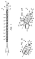
- Fig. 1 is a side view of a penetrator according to the present invention, the penetrator having a plurality of stacked penetrator segments.
- Fig. 2A is a perspective view of a penetrator segment having fins in a stowed position.
- Fig. 2B is a perspective view of a penetrator segment having fins in a deployed position.
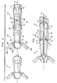
- Fig. 3 is a side view of three penetrator segments in a partially deployed configuration
- Fig. 4 is a cross-sectional view of two penetrator segments in a partially deployed configuration.
- Fig. 1 shows a penetrator 10 having a leading end 12, a trailing end 14, and a longitudinal axis 16 extending between the ends 12 and 14.
- the penetrator 10 is comprised of a plurality of stacked penetrator segments 20-29, including a leading penetrator segment 20, eight intermediate penetrator segments 21-28, and a trailing penetrator segment 29.
- Fig. 2A shows a representative individual intermediate penetrator segment, for example, intermediate penetrator segment 21, in a stowed configuration.
- the intermediate penetrator segment 21 has a nose portion 32 and a rear portion 34.
- the exterior surface ofthe nose portion 32 has a tapered, frustoconical shape.
- a protruding tip 33 having a smaller radius than nose portion 32, preferably extends forwardly from the nose portion 32.
- the rear portion 34 is preferably at least substantially in the shape of a right circular cylinder which is also coaxial with longitudinal axis 16.
- the rear portion 34 further has a rearwardly opening cavity 35 which is shown by a dashed line in Fig. 2A.
- the cavity 35 preferably has a tapered, frustoconical shape so as to be able to accommodate and to be complementary to the tapered, frustoconical shape of a nose portion of another penetrator segment.
- Cavity 35 furthermore preferably has a forwardly protruding indentation 36 that can accommodate the tip of a nose portion of a rearwardly positioned penetrator segment.
- the cavity 35 and indentation 36 are sized such that the nose and tip of a rearwardly positioned penetrator segment must be forced or press-fit into the cavity 35 and indentation 36.
- Each of four fins 37A-37D (only 37A and 37B being visible in Fig.
- a cavity 38 extends along the longitudinal axis 16 of the penetrator segment 21, and extends from the protrusion 33 through the rear portion 34 of the segment 21. As will be discussed with respect to Figs. 3 and 4, the cavity 38 can accommodate a pyrotechnic cord for facilitating separation of segments 20-29.
- Optional grooves 39 and 40 located between the nose portion 32 and the rear portion 34, allow for the penetrator 10 to be encompassed by a sabot (not shown in these figures).
- a sabot can be used to facilitate the firing ofthe penetrator 10 from a launch tube, for example, by conforming the outer shape and size of the penetrator 10, including the sabot, to the shape and size of the launch tube. Upon firing the penetrator 10 from the launch tube, the sabot would break apart and fall away from the penetrator 10.
- Fig. 2B shows the penetrator segment 21 with its fins 37A-37D in a deployed position.
- a section 41 of the rear portion 34 has a diameter that is sufficiently smaller than the maximum diameter of the nose portion 32 so that the section 41 of the rear portion 34 can accommodate the fins 37A-37D such that when they are in the stowed position they do not significantly protrude radially outwardly beyond the maximum diameter of the nose portion 32.
- the fins 37A-37D preferably have a curved shape so as to lay smoothly against the curved surface of section 41 ofthe rear portion 34.
- Fig. 3 shows an intermediate stage in the deployment of the penetrator 10 wherein two intermediate penetrator segments, for example intermediate penetrator segments 25 and 26, are still in the stacked configuration, and a third intermediate penetrator segment 27 has separated from the penetrator segment 26.
- penetrator segment 25 has a nose portion 42 having a tip 43, a rear portion 44, fins 46A-46D (46D not visible) in the stowed position, and a rearwardly opening cavity 48 having an indentation 49.
- the penetrator segment 26 has a nose portion 52 having a tip 53, a rear portion 54, fins 56A-56D (56D not visible) in the deployed position, and a rearwardly opening cavity 58 having an indentation 59.
- the nose portion 52 and tip 53 of the penetrator segment 26 are positioned within the cavity 48 and indentation 49, respectively, ofthe penetrator segment 25, so that the penetrator segments 25 and 26 are stacked in axial alignment.
- the nose portion 52 and tip 53 of penetrator segment 26 are press-fit (or force-fit) within the cavity 48 and indentation 49 respectively of penetrator segment 25 so that the segments 25 and 26 are secured together in the stacked configuration.
- an explosive element is located between each segment.
- an explosive element 60 is contained in the indentation 49 of the rearwardly opening cavity 48 ofthe segment 25 and an explosive element 61 is contained in the indentation 62 of the reawardly opening cavity 63 of the segment 24 (the segment 24 being only partially visible in the figure).
- the explosive elements are connected by a pyrotechnic cord 64 contained within a central cavity 65, which extends along the longitudinal axis 16 of the penetrator from the leading segment 20 to the trailing segment 29.
- the pyrotechnic cord 64 is activated, thereby initiating each explosive element, such as the explosive elements 60 and 61, which then causes the segments 20-29 to separate.
- each explosive element can have a separate electrical initiator or time-to-go fuze.
- Each fin for example fin 46A, has a stabilizing portion 70 and a deployment preventing arm 72 on opposite sides of a pivot pin 74.
- the pivot pin 74 runs through a pinhole 75 in the fin 46A and is mounted between two bosses 76A and 76B positioned on either side of the fin 46A (boss 76A is visible in Fig. 3; see also bosses 78A and 78B in Fig. 2B).
- Pivot pin 74 is preferably located in a plane which is perpendicular to the longitudinal axis 16.
- the stabilizing portion 70 and the deployment preventing arm 72 are positioned on opposite sides of pivot pin 74 around which the stabilizing portion 70 and the arm 72 can rotate.
- the deployment preventing arm 72 of the fin 46A is shown contacting the nose portion 52 ofthe intermediate penetrator segment 26.
- the contact of the arm 72 with the nose portion 52 prevents the fin 46A from pivoting in an outward direction; thus the fin 46A is restrained in a stowed position with the longitudinal axis of the fin 46A being substantially parallel to the longitudinal axis 16.
- arm 72 contacts the nose portion 52 of the penetrator segment 25, causing the fin 46A to remain forwardiy pivoted about pivot pin 74, thereby restraining the fin 46A in a stowed position.
- the fins 56A-56D are free to pivot to their deployed positions wherein the longitudinal axis of each fin 56A-56D is at an angle to the longitudinal axis 16.
- the stabilizing portions 80A-80D (80D not visible) of these fins 56A-56D facilitate the aerodynamic stability of the penetrator segment 26 during flight. While four fins have been illustrated for each penetrator segment, any suitable number of fins can be employed.
- each explosive element is initiated so that the segments 20-29 separate.
- the explosive elements can be simultaneously initiated so that the segments simultaneously separate, or, the explosive elements may be initiated at varying times, for example, sequentially from the rearmost explosive element forward.
- the explosive elements are initiated early in the flight ofthe penetrator 10 and at a suitably large distance from the intended target, then asymmetric aerodynamic forces acting upon the penetrator segments 20-29 after separation can cause the penetrator segments 20-29 to scatter so that the penetrator segments 20-29 impact the target in multiple locations.
- the explosive elements are initiated late in the flight of the penetrator and at a suitably close distance to an intended target, then the penetrator segments 20-29 will be substantially axially aligned upon impacting the target so that the penetrator segments 20-29 will sequentially impact the target in substantially the same location.
- the size of the stabilizing portions of the fins of each penetrator segment can be varied to control the spacing between the segments, for example, to achieve a uniform distance between the segments and a uniform velocity.
- the penetrator segments 20-29 are separated from each other, and the distance between the penetrator segments 20-29 (the amount of separation between immediately adjacent penetrator segments) can be controlled.
- the fins of the preceding segment are free to pivot to their deployed positions.
- the deployment of the fins is preferably accomplished by aerodynamic forces acting on the stabilizing portions of the fins after the segments have separated. Alternatively, deployment may be caused by a suitable mechanism such as by springs bearing the fins toward their deployed position.
- penetrator 10 is shown to have ten penetrator segments, the penetrator may have any suitable number of penetrator segments, with the potential for destroying a target increasing as more segments are used.
- the plurality of stacked penetrator segments 20-29 includes a leading penetrator segment 20 which preferably has slightly different characteristics than the intermediate penetrator segments 21-28 as described with respect to Figs. 2A-B, 3 and 4.
- the leading penetrator segment 20 preferably has an elongated, tapered nose portion 90 without a protruding tip, such as tip 33, and that has a cylindrically shaped base 92.
Landscapes
- Engineering & Computer Science (AREA)
- Chemical & Material Sciences (AREA)
- Combustion & Propulsion (AREA)
- General Engineering & Computer Science (AREA)
- Portable Nailing Machines And Staplers (AREA)
- Drilling And Exploitation, And Mining Machines And Methods (AREA)
Applications Claiming Priority (2)
| Application Number | Priority Date | Filing Date | Title |
|---|---|---|---|
| US08/896,432 US6021716A (en) | 1997-07-18 | 1997-07-18 | Penetrator having multiple impact segments |
| US896432 | 1997-07-18 |
Publications (2)
| Publication Number | Publication Date |
|---|---|
| EP0892241A2 true EP0892241A2 (de) | 1999-01-20 |
| EP0892241A3 EP0892241A3 (de) | 2000-11-22 |
Family
ID=25406203
Family Applications (1)
| Application Number | Title | Priority Date | Filing Date |
|---|---|---|---|
| EP98250179A Withdrawn EP0892241A3 (de) | 1997-07-18 | 1998-05-26 | Wuchtgeschoss mit mehrfachen Schlagwirkungssegmenten |
Country Status (4)
| Country | Link |
|---|---|
| US (1) | US6021716A (de) |
| EP (1) | EP0892241A3 (de) |
| JP (1) | JPH1137698A (de) |
| IL (1) | IL125324A (de) |
Cited By (1)
| Publication number | Priority date | Publication date | Assignee | Title |
|---|---|---|---|---|
| EP1848956A4 (de) * | 2005-02-17 | 2011-05-18 | Raytheon Co | Ke-stabgefechtskopf mit geschossbeabstandung |
Families Citing this family (24)
| Publication number | Priority date | Publication date | Assignee | Title |
|---|---|---|---|---|
| ATE349671T1 (de) * | 1997-10-17 | 2007-01-15 | Rocktek Ltd | Verfahren und vorrichtung zum räumen von hindernissen in minen |
| US6543364B2 (en) * | 2001-02-15 | 2003-04-08 | Scientific Applications & Research Associates | Less lethal multi-sensory distraction grenade |
| US6945088B2 (en) | 2002-05-14 | 2005-09-20 | The United States Of America As Represented By The Secretary Of The Navy | Multi-fragment impact test specimen |
| US6959893B1 (en) * | 2003-04-01 | 2005-11-01 | The United States Of America As Represented By The Secretary Of The Army | Light fighter lethality seeker projectile |
| US6925939B2 (en) * | 2003-04-29 | 2005-08-09 | Mark Allen Cleveland | Low shock separation bolt |
| US8661980B1 (en) | 2003-05-08 | 2014-03-04 | Lone Star Ip Holdings, Lp | Weapon and weapon system employing the same |
| US7530315B2 (en) * | 2003-05-08 | 2009-05-12 | Lone Star Ip Holdings, Lp | Weapon and weapon system employing the same |
| US7007607B1 (en) * | 2004-04-14 | 2006-03-07 | The United States Of America As Represented By The Secretary Of The Army | Missile system for breaching reinforced concrete barriers utilizing hinged explosively formed projectile warheads |
| US7690304B2 (en) * | 2005-09-30 | 2010-04-06 | Lone Star Ip Holdings, Lp | Small smart weapon and weapon system employing the same |
| US7895946B2 (en) | 2005-09-30 | 2011-03-01 | Lone Star Ip Holdings, Lp | Small smart weapon and weapon system employing the same |
| US8424233B2 (en) * | 2006-01-17 | 2013-04-23 | Metal Storm Limited | Projectile for a stacked projectile weapon |
| WO2007082334A1 (en) * | 2006-01-17 | 2007-07-26 | Metal Storm Limited | Projectile for a stacked projectile weapon |
| US7448324B1 (en) * | 2006-05-03 | 2008-11-11 | At&T Intellectual Property Ii, L.P. | Segmented rod projectile |
| US8541724B2 (en) | 2006-09-29 | 2013-09-24 | Lone Star Ip Holdings, Lp | Small smart weapon and weapon system employing the same |
| US8117955B2 (en) | 2006-10-26 | 2012-02-21 | Lone Star Ip Holdings, Lp | Weapon interface system and delivery platform employing the same |
| IL179224A (en) * | 2006-11-13 | 2012-09-24 | Rafael Advanced Defense Sys | Combat head for interception system |
| US8119956B2 (en) * | 2008-10-02 | 2012-02-21 | Raytheon Company | Multi-stage hyper-velocity kinetic energy missile |
| US8438977B2 (en) * | 2008-12-25 | 2013-05-14 | Lockheed Martin Corporation | Projectile having deployable fin |
| US8434411B2 (en) | 2011-01-19 | 2013-05-07 | Raytheon Company | Cluster explosively-formed penetrator warheads |
| US9068803B2 (en) | 2011-04-19 | 2015-06-30 | Lone Star Ip Holdings, Lp | Weapon and weapon system employing the same |
| US9194678B2 (en) * | 2012-04-25 | 2015-11-24 | Wilcox Industries Corp. | Modular rocket system |
| RU2511517C1 (ru) * | 2012-12-28 | 2014-04-10 | Федеральное государственное бюджетное образовательное учреждение высшего профессионального образования "Московский государственный технический университет имени Н.Э. Баумана" (МГТУ им. Н.Э. Баумана) | Раздвигающая пучковая боевая часть "могоча" |
| RU2637665C1 (ru) * | 2016-10-10 | 2017-12-06 | Владимир Викторович Черниченко | Надкалиберная пучковая граната "вартава" к ручному гранатомету |
| IL285253B2 (en) * | 2021-07-27 | 2023-08-01 | Rafael Advanced Defense Systems Ltd | Ammunition breaks through barriers |
Citations (6)
| Publication number | Priority date | Publication date | Assignee | Title |
|---|---|---|---|---|
| US4635556A (en) | 1982-03-17 | 1987-01-13 | Rheinmetall Gmbh | Penetrator shell with stacked core elements |
| US4708064A (en) | 1977-09-29 | 1987-11-24 | Rheinmetall Gmbh | Impact projectile |
| US4716834A (en) | 1980-03-27 | 1988-01-05 | Rheinmetall Gmbh | Inertial penetrator projectile |
| US4901645A (en) | 1980-08-23 | 1990-02-20 | Rheinmetall, Gmbh | Inertial projectile having a breakable pre-penetrator |
| US5088416A (en) | 1978-10-19 | 1992-02-18 | Rheinmetall Gmbh | Impact projectile |
| US5526752A (en) | 1994-09-06 | 1996-06-18 | Rockwell International Corporation | Weapon for destruction of deeply buried and hardened targets |
Family Cites Families (20)
| Publication number | Priority date | Publication date | Assignee | Title |
|---|---|---|---|---|
| US395881A (en) * | 1889-01-08 | Patrick citxxingiiam | ||
| FR493294A (fr) * | 1916-03-01 | 1919-08-05 | Joseph Paonessa | Obus à répétition |
| US2870710A (en) * | 1954-03-10 | 1959-01-27 | Roland E Miedel | Compound projectile with separable sections |
| US2804823A (en) * | 1955-05-13 | 1957-09-03 | Jablansky Louis | Multiple unit projectile |
| US2945442A (en) * | 1958-01-02 | 1960-07-19 | Barnet R Adelman | Explosive separation device |
| DE1231139B (de) * | 1964-04-17 | 1966-12-22 | Kunststofftechnische Studienge | Flugkoerper mit Raketenantrieb |
| US3316780A (en) * | 1966-01-14 | 1967-05-02 | Edward C Herkner | Broken rifle shell extractor |
| DE2242930C2 (de) * | 1972-08-31 | 1987-01-02 | Rheinmetall GmbH, 4000 Düsseldorf | Hohlladungstochtergeschoß |
| US4492166A (en) * | 1977-04-28 | 1985-01-08 | Martin Marietta Corporation | Submunition having terminal trajectory correction |
| FR2535450B1 (fr) * | 1981-03-05 | 1986-11-14 | Saint Louis Inst | Projectile perforant |
| DE3207220A1 (de) * | 1982-02-27 | 1983-09-08 | Rheinmetall GmbH, 4000 Düsseldorf | Geschossanordnung |
| US4565340A (en) * | 1984-08-15 | 1986-01-21 | Ford Aerospace & Communications Corporation | Guided projectile flight control fin system |
| DE3609092A1 (de) * | 1986-03-19 | 1990-11-22 | Rheinmetall Gmbh | Geschoss fuer eine rohrwaffe zum bekaempfen aktiv und passiv reagierender sonderpanzerungen |
| DE3643294A1 (de) * | 1986-12-18 | 1988-06-23 | Rheinmetall Gmbh | Geschoss |
| FR2609542B1 (fr) * | 1987-01-14 | 1994-05-06 | Serat | Perfectionnements apportes aux projectiles a charges creuses tandem |
| DE3834925A1 (de) * | 1988-10-13 | 1990-04-19 | Siegfried Trost | Huelsenlose munition, fuer insbesondere kalibergleiche sturm-, maschinen- und scharfschuetzengewehre |
| DE4007810A1 (de) * | 1990-03-12 | 1991-09-19 | Werner Beiter | Pfeilspitze |
| USH905H (en) * | 1990-09-13 | 1991-04-02 | The United States Of America As Represented By The Secretary Of The Army | Fin assembly |
| DE4031208A1 (de) * | 1990-10-04 | 1992-04-09 | Rheinmetall Gmbh | Segmentierter treibkaefig fuer ein tandemgeschoss |
| US5245927A (en) * | 1992-04-28 | 1993-09-21 | Northrop Corporation | Dual-tandem unmanned air vehicle system |
-
1997
- 1997-07-18 US US08/896,432 patent/US6021716A/en not_active Expired - Fee Related
-
1998
- 1998-05-26 EP EP98250179A patent/EP0892241A3/de not_active Withdrawn
- 1998-07-07 JP JP10205814A patent/JPH1137698A/ja active Pending
- 1998-07-13 IL IL12532498A patent/IL125324A/xx not_active IP Right Cessation
Patent Citations (6)
| Publication number | Priority date | Publication date | Assignee | Title |
|---|---|---|---|---|
| US4708064A (en) | 1977-09-29 | 1987-11-24 | Rheinmetall Gmbh | Impact projectile |
| US5088416A (en) | 1978-10-19 | 1992-02-18 | Rheinmetall Gmbh | Impact projectile |
| US4716834A (en) | 1980-03-27 | 1988-01-05 | Rheinmetall Gmbh | Inertial penetrator projectile |
| US4901645A (en) | 1980-08-23 | 1990-02-20 | Rheinmetall, Gmbh | Inertial projectile having a breakable pre-penetrator |
| US4635556A (en) | 1982-03-17 | 1987-01-13 | Rheinmetall Gmbh | Penetrator shell with stacked core elements |
| US5526752A (en) | 1994-09-06 | 1996-06-18 | Rockwell International Corporation | Weapon for destruction of deeply buried and hardened targets |
Cited By (1)
| Publication number | Priority date | Publication date | Assignee | Title |
|---|---|---|---|---|
| EP1848956A4 (de) * | 2005-02-17 | 2011-05-18 | Raytheon Co | Ke-stabgefechtskopf mit geschossbeabstandung |
Also Published As
| Publication number | Publication date |
|---|---|
| IL125324A (en) | 2001-08-26 |
| EP0892241A3 (de) | 2000-11-22 |
| JPH1137698A (ja) | 1999-02-12 |
| IL125324A0 (en) | 1999-03-12 |
| US6021716A (en) | 2000-02-08 |
Similar Documents
| Publication | Publication Date | Title |
|---|---|---|
| US6021716A (en) | Penetrator having multiple impact segments | |
| US5988071A (en) | Penetrator having multiple impact segments, including an explosive segment | |
| US5834684A (en) | Penetrator having multiple impact segments | |
| JP4199118B2 (ja) | 複数の発射体が整列される弾頭 | |
| JP4057590B2 (ja) | タンデム弾頭 | |
| US4648324A (en) | Projectile with enhanced target penetrating power | |
| US4671181A (en) | Anti-tank shell | |
| US4922826A (en) | Active component of submunition, as well as flechette warhead and flechettes therefor | |
| ES2273375T3 (es) | Proyectil o cabeza de combate. | |
| US4648323A (en) | Fragmentation munition | |
| US3903804A (en) | Rocket-propelled cluster weapon | |
| US8661980B1 (en) | Weapon and weapon system employing the same | |
| US20110179963A1 (en) | Weapon and Weapon System Employing the Same | |
| JP4430070B2 (ja) | 放出角度が低減された運動エネルギー式ロッド型弾頭 | |
| CN1430720A (zh) | 导弹的方向控制 | |
| US4080900A (en) | Projectile | |
| EP0350821A2 (de) | Gefechtskopf | |
| US3677179A (en) | Telescoping ordnance device | |
| US3427976A (en) | Ordnance projectile | |
| US20100307364A1 (en) | Pyrophoric arrows | |
| EP0298494B1 (de) | Submunitions-Wirkteil, sowie Flechettes-Gefechtskopf und Flechettes dafür | |
| US7856928B1 (en) | Countermine dart system and method | |
| JP2006520882A (ja) | 発射体を等方的に発射する運動エネルギーロッド弾頭 | |
| US3750575A (en) | Spin-stabilized projectile | |
| US9476682B1 (en) | Multi-charge munitions, incorporating hole-boring charge assemblies |
Legal Events
| Date | Code | Title | Description |
|---|---|---|---|
| PUAI | Public reference made under article 153(3) epc to a published international application that has entered the european phase |
Free format text: ORIGINAL CODE: 0009012 |
|
| AK | Designated contracting states |
Kind code of ref document: A2 Designated state(s): AT BE CH CY DE DK ES FI FR GB GR IE IT LI LU MC NL PT SE |
|
| AX | Request for extension of the european patent |
Free format text: AL;LT;LV;MK;RO;SI |
|
| PUAL | Search report despatched |
Free format text: ORIGINAL CODE: 0009013 |
|
| AK | Designated contracting states |
Kind code of ref document: A3 Designated state(s): AT BE CH CY DE DK ES FI FR GB GR IE IT LI LU MC NL PT SE |
|
| AX | Request for extension of the european patent |
Free format text: AL;LT;LV;MK;RO;SI |
|
| AKX | Designation fees paid | ||
| REG | Reference to a national code |
Ref country code: DE Ref legal event code: 8566 |
|
| STAA | Information on the status of an ep patent application or granted ep patent |
Free format text: STATUS: THE APPLICATION IS DEEMED TO BE WITHDRAWN |
|
| 18D | Application deemed to be withdrawn |
Effective date: 20010523 |