EP0892234B1 - Vorrichtung zur Verwendung für ein Wirbelschichtfeststoffsystem - Google Patents
Vorrichtung zur Verwendung für ein Wirbelschichtfeststoffsystem Download PDFInfo
- Publication number
- EP0892234B1 EP0892234B1 EP98111796A EP98111796A EP0892234B1 EP 0892234 B1 EP0892234 B1 EP 0892234B1 EP 98111796 A EP98111796 A EP 98111796A EP 98111796 A EP98111796 A EP 98111796A EP 0892234 B1 EP0892234 B1 EP 0892234B1
- Authority
- EP
- European Patent Office
- Prior art keywords
- fluidizing gas
- nozzles
- inlet
- nozzle
- vessel
- Prior art date
- Legal status (The legal status is an assumption and is not a legal conclusion. Google has not performed a legal analysis and makes no representation as to the accuracy of the status listed.)
- Expired - Lifetime
Links
- 239000007787 solid Substances 0.000 title claims description 27
- 230000001133 acceleration Effects 0.000 abstract description 3
- 239000007789 gas Substances 0.000 description 49
- XEEYBQQBJWHFJM-UHFFFAOYSA-N Iron Chemical compound [Fe] XEEYBQQBJWHFJM-UHFFFAOYSA-N 0.000 description 13
- 230000009467 reduction Effects 0.000 description 8
- 229910052742 iron Inorganic materials 0.000 description 6
- 238000000034 method Methods 0.000 description 5
- 230000008569 process Effects 0.000 description 5
- UQSXHKLRYXJYBZ-UHFFFAOYSA-N iron oxide Inorganic materials [Fe]=O UQSXHKLRYXJYBZ-UHFFFAOYSA-N 0.000 description 3
- 235000013980 iron oxide Nutrition 0.000 description 3
- VBMVTYDPPZVILR-UHFFFAOYSA-N iron(2+);oxygen(2-) Chemical class [O-2].[Fe+2] VBMVTYDPPZVILR-UHFFFAOYSA-N 0.000 description 3
- 230000004048 modification Effects 0.000 description 2
- 238000012986 modification Methods 0.000 description 2
- UGFAIRIUMAVXCW-UHFFFAOYSA-N Carbon monoxide Chemical compound [O+]#[C-] UGFAIRIUMAVXCW-UHFFFAOYSA-N 0.000 description 1
- UFHFLCQGNIYNRP-UHFFFAOYSA-N Hydrogen Chemical compound [H][H] UFHFLCQGNIYNRP-UHFFFAOYSA-N 0.000 description 1
- 230000002411 adverse Effects 0.000 description 1
- 230000001174 ascending effect Effects 0.000 description 1
- 230000009286 beneficial effect Effects 0.000 description 1
- 229910002091 carbon monoxide Inorganic materials 0.000 description 1
- 238000010276 construction Methods 0.000 description 1
- 230000001419 dependent effect Effects 0.000 description 1
- 230000008021 deposition Effects 0.000 description 1
- 238000011161 development Methods 0.000 description 1
- 230000018109 developmental process Effects 0.000 description 1
- 229910052739 hydrogen Inorganic materials 0.000 description 1
- 239000001257 hydrogen Substances 0.000 description 1
- 230000002452 interceptive effect Effects 0.000 description 1
- 230000014759 maintenance of location Effects 0.000 description 1
- 230000007246 mechanism Effects 0.000 description 1
- 239000013528 metallic particle Substances 0.000 description 1
- 239000000203 mixture Substances 0.000 description 1
- 239000002245 particle Substances 0.000 description 1
- 238000005476 soldering Methods 0.000 description 1
Images

Classifications
-
- C—CHEMISTRY; METALLURGY
- C21—METALLURGY OF IRON
- C21B—MANUFACTURE OF IRON OR STEEL
- C21B13/00—Making spongy iron or liquid steel, by direct processes
- C21B13/0033—In fluidised bed furnaces or apparatus containing a dispersion of the material
-
- B—PERFORMING OPERATIONS; TRANSPORTING
- B01—PHYSICAL OR CHEMICAL PROCESSES OR APPARATUS IN GENERAL
- B01J—CHEMICAL OR PHYSICAL PROCESSES, e.g. CATALYSIS OR COLLOID CHEMISTRY; THEIR RELEVANT APPARATUS
- B01J8/00—Chemical or physical processes in general, conducted in the presence of fluids and solid particles; Apparatus for such processes
- B01J8/18—Chemical or physical processes in general, conducted in the presence of fluids and solid particles; Apparatus for such processes with fluidised particles
- B01J8/1818—Feeding of the fluidising gas
-
- B—PERFORMING OPERATIONS; TRANSPORTING
- B01—PHYSICAL OR CHEMICAL PROCESSES OR APPARATUS IN GENERAL
- B01J—CHEMICAL OR PHYSICAL PROCESSES, e.g. CATALYSIS OR COLLOID CHEMISTRY; THEIR RELEVANT APPARATUS
- B01J8/00—Chemical or physical processes in general, conducted in the presence of fluids and solid particles; Apparatus for such processes
- B01J8/18—Chemical or physical processes in general, conducted in the presence of fluids and solid particles; Apparatus for such processes with fluidised particles
- B01J8/24—Chemical or physical processes in general, conducted in the presence of fluids and solid particles; Apparatus for such processes with fluidised particles according to "fluidised-bed" technique
- B01J8/44—Fluidisation grids
-
- F—MECHANICAL ENGINEERING; LIGHTING; HEATING; WEAPONS; BLASTING
- F27—FURNACES; KILNS; OVENS; RETORTS
- F27B—FURNACES, KILNS, OVENS OR RETORTS IN GENERAL; OPEN SINTERING OR LIKE APPARATUS
- F27B15/00—Fluidised-bed furnaces; Other furnaces using or treating finely-divided materials in dispersion
- F27B15/02—Details, accessories or equipment specially adapted for furnaces of these types
- F27B15/10—Arrangements of air or gas supply devices
-
- Y—GENERAL TAGGING OF NEW TECHNOLOGICAL DEVELOPMENTS; GENERAL TAGGING OF CROSS-SECTIONAL TECHNOLOGIES SPANNING OVER SEVERAL SECTIONS OF THE IPC; TECHNICAL SUBJECTS COVERED BY FORMER USPC CROSS-REFERENCE ART COLLECTIONS [XRACs] AND DIGESTS
- Y02—TECHNOLOGIES OR APPLICATIONS FOR MITIGATION OR ADAPTATION AGAINST CLIMATE CHANGE
- Y02P—CLIMATE CHANGE MITIGATION TECHNOLOGIES IN THE PRODUCTION OR PROCESSING OF GOODS
- Y02P10/00—Technologies related to metal processing
- Y02P10/10—Reduction of greenhouse gas [GHG] emissions
- Y02P10/134—Reduction of greenhouse gas [GHG] emissions by avoiding CO2, e.g. using hydrogen
Definitions
- the present invention relates to an apparatus for use in fluidized solid systems and, more particularly, an apparatus which is particularly useful in the direct reduction of iron ores in a fluidized bed process.
- a fluidized process of considerable importance relates to the direct reduction of iron ores.
- iron oxides are progressively reduced in a vertical vessel (reactor) having a single reduction stage or, more commonly, a series of reduction stages.
- the ore to be reduced is fed into the top of the vessel and flows downwardly in counter current relationship to the flow of a fluidizing gas ascending in the vessel.
- the fluidizing gas comprises a hot reducing gas which consists generally of carbon monoxide, hydrogen and other known gas mixtures.
- the fluidizing gases are delivered to the fluidizing bed for contact with the iron ore through a plurality of nozzles and provided in a horizontal wall disposed within the vessel.
- the fouling or plugging of the nozzles is associated with adherence of "fines" of metallic particles which adhere to the inner walls of the nozzles, build up on the inner walls and eventually plug the nozzles completely. It has been proposed in U.S.
- Patent 3,910,769 to provide a baffle at the fluidizing gas inlet in combination with conical shaped nozzles so as to provide a preferential flow through the nozzles in a manner which would avoid adherence of the fines to the interior wall surface of the nozzles. While such a design has proven to be beneficial, the design has resulted in problems particularly with respect to the outer rings of nozzles. It has been found that the baffle plate causes a preferential deposition of the fines in the outer rings of the nozzles and, more particularly, on a portion of the wall of the outer ring of the nozzles. This build-up results from a flow caused by the baffle plate which results in strong cross-flow at the nozzle inlets. Accordingly, the principal object of the present invention to provide a mechanism which eliminates the cross-flow at the nozzle inlets of the outer ring of nozzles thereby eliminating the excess build-up of fines on the outer ring of nozzles.
- the document US-A-3910769 describe a fluidized bed furnace having a vessel, a solid inlet, a fluidizing gas inlet for counter current gas flow, a solids outlet, a fluidizing gas outlet, a wall for dividing vessel into fluidized solid section, a fluidizing gas feed section, a plurality of gas nozzles located in said wall, a baffle and a plate means.
- the document EP-A-453209 shows a gas distributor used for a gas-fluidized bed equipment having a nozzle and support means used for securing a retention plate ore a plate mean at a certain distance from the nozzle inlet, preventing particles from dropping further below the nozzle.
- At least the outer rings of nozzles in a fluidized bed apparatus is provided with a plate proximate to the nozzle inlet which redirects the flow of the fluidizing gas to the nozzles.
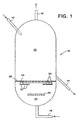
- a vertical reactor 10 of the type employed in the direct reduction of iron oxides.
- Particulate iron ore solids are fed to the vessel 10 via solids inlet 12 at the top of the vessel 10.
- the reduced iron ore is removed from the bottom of the vessel 10 via solids outlet 14.
- a fluidizing gas in the form of a hot reducing gas is fed into the bottom of the vessel 10 via fluidizing gas inlet 16.
- the spent reducing gas is recovered from the top of the vessel 10 via line 18.
- the vessel 10 is divided by wall means 20 into a fluidized solids section 22 above wall means 20 and a fluidizing gas feed section 24 below the wall 20.
- the fluidizing gas feed section is provided with a baffle 26 proximate to and downstream of the inlet 16 for distributing the fluidizing gas fed from the fluidizing gas inlet 16 toward a plurality of nozzles 28 provided in wall 20.
- the baffle 26 causes a preferential cross-flow at the inlet of the outer ring of nozzles 28 provided in the wall 20. This results in a build-up of fines on a portion of the wall 30 of the outer ring of nozzles.
- at least the outer rings of nozzles 28 in wall 20 are provided with individual plates 32 which act to redirect the fluidizing gas so as to provide good distribution of flow of the fluidizing gas through the nozzles 28.
- Each of the nozzles 28, or at least the nozzles which comprise the outer ring of nozzles 28 in wall member 20, is provided with a plate 32 proximate to the inlet opening 34 of the nozzle for redirecting the flow of the fluidizing gas so as to achieve uniform fluidizing gas flow through the nozzle.
- the plate 32 has a diameter Dp which is greater than the inlet diameter Di of the nozzle 28.
- the plate 32 should be spaced from the inlet 34 of the nozzle a relatively short distance H in order to insure effective redirecting of the fluidizing gas flow while at the same time not adversely affecting the access of the fluidizing gas to the inlet 34 of the nozzle 28.
- the distance H in combination with the diameter Dp of the plate insure optimum flow of the fluidizing gas through the nozzle 28.
- the nozzles 28 are conical shaped having sidewalls which form an angle ⁇ which insures acceleration of the fluidizing gas through the nozzle so as to further prevent the adherence of fines to the inside surface of the nozzles.
- the shape and size of the nozzle 28 in combination with the size and location of the plate 32 relative to the inlet 34 of the nozzle insures optimum fluidizing gas flow.
- the conical shaped nozzles have a length of between about 330 mm to 450 mm, an inlet diameter Di of between about 100 mm to 120 mm, an outlet diameter Do of between about 35 mm to 45 mm, and an angle ⁇ of between about 5° to about 8° are particularly useful in fluidized bed reactors used in the direct reduction of iron oxides.
- the plate 32 should be disposed from the inlet 34 and the nozzle 28 a distance H of between about 125 mm to about 225 mm and that the diameter Dp of the plate should be between 150 mm to 230 mm.
- the design of the plate 32 with respect to the nozzle 28 as set forth above optimizes the redirection of the fluidizing gas and the flow of the fluidizing gas through the nozzle 28.
- ratio (Di-Do)/L is between 0.175 to 0.281
- ratio (Di/Do) is between 2.6 to 4.8
- angle ⁇ of between about 5° to 8°.
- the plate 32 is secured to the nozzle 28 at the desired distance H by means of a plurality of support members 36 in the form of rods or the like which are secured to the nozzle at an angular spacing of about 120° as illustrated in Figure 3.
- the rods 36 may be secured to the nozzle 28 and to the plate 32 by means of soldering or the like.
- the rods 36 are made as small as possible so as to provide the necessary support for the plate 32 on the nozzle 28 while at the same time not interfering with the access of the fluidizing gas to the inlet 34 of the nozzle 28.
- the nozzle design of the present invention insures a smooth access to the inlet 34 of the nozzle 28 by fluidizing gas, eliminates the problem of strong cross-flow at the inlet of the nozzles and thus eliminates the selective buildup of fines on the outside surfaces of the nozzles particularly with regard to the nozzles in the outer ring of the wall 20.
- all of the nozzles may be provided with a plate 32 in accordance with the present invention; however, in certain applications it may only be necessary to provide the nozzles of the outer ring of nozzles with the plates 32.
Landscapes
- Chemical & Material Sciences (AREA)
- Engineering & Computer Science (AREA)
- Organic Chemistry (AREA)
- Dispersion Chemistry (AREA)
- Chemical Kinetics & Catalysis (AREA)
- Combustion & Propulsion (AREA)
- Manufacturing & Machinery (AREA)
- Metallurgy (AREA)
- Materials Engineering (AREA)
- Mechanical Engineering (AREA)
- General Engineering & Computer Science (AREA)
- Devices And Processes Conducted In The Presence Of Fluids And Solid Particles (AREA)
- Crucibles And Fluidized-Bed Furnaces (AREA)
- Fluidized-Bed Combustion And Resonant Combustion (AREA)
Claims (8)
- Ofenvorrichtung zur Verwendung für ein Wirbelschichtfeststoffsystem, bestehend aus:einem Behälter (10), der einen Durchflußweg für die Wirbelschichtfeststoffe bezeichnet;einem Feststoffeinlaß (12) zum Zuführen von Feststoffen in den Behälter in einer ersten Richtung;einem Wirbelgaseinlaß (16) zum Zuführen von Wirbelgas in den Behälter in einer zweiten Richtung, die der ersten Richtung im Wesentlichen entgegengesetzt ist;einem Feststoffauslaß (14) zum Entfernen der Wirbelschichtfeststoffe aus dem Behälter;einem Wirbelgasauslaß (18) zum Entfernen des Wirbelgases aus dem Behälter;einem im Behälter zwischen dem Feststoffeinlaß und dem Wirbelgaseinlaß angeordneten Wandmittel (20) zur Unterteilung des Behälters in einen Wirbelschichtfeststoffabschnitt (22) und einen Wirbelgaszuführabschnitt (24);mehreren im Wandmittel angeordneten Düsen (28), wobei jede dieser Düsen einen Einlaß und einen Auslaß zur Übertragung des Wirbelgases vom Wirbelgaszuführabschnitt in den Wirbelschichtfeststoffabschnitt aufweist;einem im Wirbelgaszuführabschnitt zwischen dem Wandmittel und dem Wirbelgaseinlaß angeordneten Ablenkmittel (26) zur Verteilung des aus dem Wirbelgaseinlaß zugeführten Wirbelgases in Richtung der Düsen;und einer nahe des Einlasses zumindest einiger der Düsen und in einem Abstand zu diesen angeordneten Platteneinrichtung (32) zur Umleitung des Wirbelgasstromes durch zumindest einige dieser Düsen, wobei die Düse kegelförmig ist und einen Einlaßdurchmesser Di aufweist, die Platteneinrichtung einen Durchmesser Dp zwischen 150 mm und 230 mm aufweist und das Verhältnis (Dp/Di) zwischen 1,3 und 1,6 beträgt und die Platteneinrichtung ein Tragmittel umfaßt, welches an den Düsen zum Halten der Platteneinrichtung über dem Düseneinlaß in einem Abstand H zu diesem angebracht ist, und das Verhältnis des Abstandes H zur Länge L der Düse (L/H) zwischen 2 und 4,1 beträgt.
- Vorrichtung nach Anspruch 1, bei welcher H zwischen 125 mm und 225 mm beträgt.
- Vorrichtung nach Anspruch 1 oder 2, bei welcher das Tragmittel drei Stäbe (36) umfaßt, die in einem Winkel von 120° an der Düse befestigt sind.
- Vorrichtung nach einem der Ansprüche 1 bis 3, bei welcher die kegelförmigen Düsen einen Seitenwandabschnitt aufweisen, der einen Winkel a von zwischen 5° und 8° bildet.
- Vorrichtung nach Anspruch 1, bei welcher die kegelige Form einen Auslaßdurchmesser Do aufweist, bei der Di größer ist als Do.
- Vorrichtung nach Anspruch 5, bei welcher Do zwischen 35 mm und 45 mm, Di zwischen 100 mm und 120 mm aufweist und die Düse über eine Länge L von zwischen 330 mm und 450 mm verfügt.
- Vorrichtung nach Anspruch 5 oder 6, bei welcher das Verhältnis (Di/Do) zwischen 2,6 und 4,8 beträgt.
- Vorrichtung nach einem der Ansprüche 5 bis 7, bei welcher das Verhältnis (Di-Do)/L zwischen 0,175 und 0,281 beträgt, wobei L die Länge der Düsen darstellt.
Applications Claiming Priority (2)
| Application Number | Priority Date | Filing Date | Title |
|---|---|---|---|
| US08/882,887 US5904119A (en) | 1997-06-26 | 1997-06-26 | Furnace apparatus for fluidized bed processes |
| US882887 | 1997-06-26 |
Publications (3)
| Publication Number | Publication Date |
|---|---|
| EP0892234A2 EP0892234A2 (de) | 1999-01-20 |
| EP0892234A3 EP0892234A3 (de) | 1999-03-03 |
| EP0892234B1 true EP0892234B1 (de) | 2002-12-18 |
Family
ID=25381545
Family Applications (1)
| Application Number | Title | Priority Date | Filing Date |
|---|---|---|---|
| EP98111796A Expired - Lifetime EP0892234B1 (de) | 1997-06-26 | 1998-06-26 | Vorrichtung zur Verwendung für ein Wirbelschichtfeststoffsystem |
Country Status (5)
| Country | Link |
|---|---|
| US (1) | US5904119A (de) |
| EP (1) | EP0892234B1 (de) |
| AT (1) | ATE230099T1 (de) |
| AU (1) | AU696128B1 (de) |
| DE (1) | DE69810202T2 (de) |
Families Citing this family (4)
| Publication number | Priority date | Publication date | Assignee | Title |
|---|---|---|---|---|
| AUPO715497A0 (en) * | 1997-06-03 | 1997-06-26 | Noonan, Gregory Joseph | Improving the flow field in the inlet plenum of a fluidised bed |
| KR100542546B1 (ko) * | 2004-05-07 | 2006-01-11 | 조선내화 주식회사 | 분철광석의 환원을 위한 유동층 환원로의 분산판 지지용지주대 구조 |
| KR102329735B1 (ko) * | 2018-08-24 | 2021-11-22 | 주식회사 엘지화학 | 코팅기 |
| CN109499262B (zh) * | 2018-12-14 | 2021-08-13 | 青岛科技大学 | 一种新型纵向平行床吸附器 |
Family Cites Families (12)
| Publication number | Priority date | Publication date | Assignee | Title |
|---|---|---|---|---|
| GB811366A (en) * | 1956-02-29 | 1959-04-02 | United Steel Companies Ltd | Improvements in and relating to fluidising |
| DE1166158B (de) * | 1959-11-09 | 1964-03-26 | United Steel Companies Ltd | Rost fuer Wirbelschichtreaktoren |
| GB1119250A (en) * | 1964-10-30 | 1968-07-10 | United Steel Companies Ltd | Containers for beds of fluidised particles and processes carried out in them |
| GB1265004A (de) * | 1968-10-25 | 1972-03-01 | ||
| US3910769A (en) * | 1972-12-06 | 1975-10-07 | Exxon Research Engineering Co | Apparatus for fluidized solid systems |
| HU172289B (hu) * | 1975-12-09 | 1978-07-28 | Richter Gedeon Vegyeszet | Mekhanizm dlja sozdanija psevdozhidkogo sloja pri sushke sypuchikh tvjordykh materialov |
| US4115929A (en) * | 1976-10-27 | 1978-09-26 | Electric Power Research Institute, Inc. | Gas distributor for fluidizing beds |
| US4257171A (en) * | 1979-07-16 | 1981-03-24 | Stone & Webster Engineering Corp. | Fluidized bed gas distributor system |
| FI860660L (fi) * | 1986-02-13 | 1987-08-14 | Seppo Kalervo Ruottu | Foerfarande foer reglering av gasstroemmars blandning. |
| US5183641A (en) * | 1988-08-16 | 1993-02-02 | A. Ahlstrom Corporation | Distributor plate in a fluidized bed reactor |
| FR2650204B1 (fr) * | 1989-07-26 | 1993-07-16 | Saint Gobain Isover | Procede et dispositif pour le traitement de dechets de verre ou de fibres minerales en vue de leur recuperation |
| JPH03296430A (ja) * | 1990-04-17 | 1991-12-27 | Mitsui Toatsu Chem Inc | 流動層装置用粉体落下防止分散盤 |
-
1997
- 1997-06-26 US US08/882,887 patent/US5904119A/en not_active Expired - Fee Related
-
1998
- 1998-05-06 AU AU64772/98A patent/AU696128B1/en not_active Ceased
- 1998-06-26 DE DE69810202T patent/DE69810202T2/de not_active Expired - Fee Related
- 1998-06-26 EP EP98111796A patent/EP0892234B1/de not_active Expired - Lifetime
- 1998-06-26 AT AT98111796T patent/ATE230099T1/de not_active IP Right Cessation
Also Published As
| Publication number | Publication date |
|---|---|
| ATE230099T1 (de) | 2003-01-15 |
| EP0892234A3 (de) | 1999-03-03 |
| AU696128B1 (en) | 1998-09-03 |
| US5904119A (en) | 1999-05-18 |
| EP0892234A2 (de) | 1999-01-20 |
| DE69810202D1 (de) | 2003-01-30 |
| DE69810202T2 (de) | 2003-10-09 |
Similar Documents
| Publication | Publication Date | Title |
|---|---|---|
| EP0355690B1 (de) | Schneller Wirbelschichtreaktor | |
| US3974091A (en) | Fluidized bed regeneration of carbon-contaminated catalysts using gas discharge nozzles of specific dimensions | |
| US8021600B2 (en) | Method and plant for the heat treatment of solids containing iron oxide | |
| EP1499434B1 (de) | Fliessbettrost und verfahren zum entfernen von grosskörnigen feststoffen aus einem fliessbettreaktor | |
| HU203683B (en) | Method and apparatus for directing polymerization reactions influidized bed | |
| US4032300A (en) | Oxygen-containing gas distribution apparatus employed in fluidized bed regeneration of carbon-contaminated catalysts | |
| EP0622116B1 (de) | Verfahren und Apparat zum Verteilen von Fluiden in einem Behälter | |
| EP0892234B1 (de) | Vorrichtung zur Verwendung für ein Wirbelschichtfeststoffsystem | |
| EP0700316B1 (de) | Methode und vorrichtung zur behandlung von bettmaterial in fliessbettreaktoren | |
| EP0777758A1 (de) | Anordnung in einer wand und verfahren zum beschichten einer wand | |
| US20050028874A1 (en) | Gas distributor for reactors | |
| US5607893A (en) | Method for uniform loading of catalyst tubes | |
| EP0085610A2 (de) | Wirbelbettgasverteiler | |
| JP2991201B1 (ja) | 反応装置 | |
| JP7222412B2 (ja) | ガスの分配装置 | |
| KR100317660B1 (ko) | 유동베드처리용의개량된노장치 | |
| US4251926A (en) | Gas distributor apparatus for fluidized bed reactor | |
| KR100875337B1 (ko) | 유동층의 입구 플리넘에서 유동영역의 개선장치 | |
| JP2024525356A (ja) | プレートグリッド分配器を有する化学処理容器及びその操作方法 | |
| USRE33230E (en) | Fluidized bed reactor | |
| KR100641466B1 (ko) | 샤프트 로 | |
| EP1575699B1 (de) | Verfahren und vorrichtung für eine thermische behandlung in einem wirbelbett | |
| US4711039A (en) | Fluidized beds | |
| JP2653991B2 (ja) | 流動層炉 | |
| KR20250097815A (ko) | 유체 유도기를 갖는 화학적 처리 용기 및 이의 작동 방법 |
Legal Events
| Date | Code | Title | Description |
|---|---|---|---|
| PUAI | Public reference made under article 153(3) epc to a published international application that has entered the european phase |
Free format text: ORIGINAL CODE: 0009012 |
|
| PUAL | Search report despatched |
Free format text: ORIGINAL CODE: 0009013 |
|
| 17P | Request for examination filed |
Effective date: 19980722 |
|
| AK | Designated contracting states |
Kind code of ref document: A2 Designated state(s): AT DE GB NL |
|
| AX | Request for extension of the european patent |
Free format text: AL;LT;LV;MK;RO;SI |
|
| AK | Designated contracting states |
Kind code of ref document: A3 Designated state(s): AT BE CH CY DE DK ES FI FR GB GR IE IT LI LU MC NL PT SE |
|
| AX | Request for extension of the european patent |
Free format text: AL;LT;LV;MK;RO;SI |
|
| AKX | Designation fees paid |
Free format text: AT DE GB NL |
|
| AXX | Extension fees paid |
Free format text: RO PAYMENT 19990716 |
|
| 17Q | First examination report despatched |
Effective date: 20010403 |
|
| GRAG | Despatch of communication of intention to grant |
Free format text: ORIGINAL CODE: EPIDOS AGRA |
|
| GRAG | Despatch of communication of intention to grant |
Free format text: ORIGINAL CODE: EPIDOS AGRA |
|
| GRAH | Despatch of communication of intention to grant a patent |
Free format text: ORIGINAL CODE: EPIDOS IGRA |
|
| GRAH | Despatch of communication of intention to grant a patent |
Free format text: ORIGINAL CODE: EPIDOS IGRA |
|
| GRAA | (expected) grant |
Free format text: ORIGINAL CODE: 0009210 |
|
| AK | Designated contracting states |
Kind code of ref document: B1 Designated state(s): AT DE GB NL |
|
| AX | Request for extension of the european patent |
Free format text: RO PAYMENT 19990716 |
|
| REF | Corresponds to: |
Ref document number: 230099 Country of ref document: AT Date of ref document: 20030115 Kind code of ref document: T |
|
| REG | Reference to a national code |
Ref country code: GB Ref legal event code: FG4D |
|
| REF | Corresponds to: |
Ref document number: 69810202 Country of ref document: DE Date of ref document: 20030130 Kind code of ref document: P Ref document number: 69810202 Country of ref document: DE Date of ref document: 20030130 |
|
| PLBE | No opposition filed within time limit |
Free format text: ORIGINAL CODE: 0009261 |
|
| STAA | Information on the status of an ep patent application or granted ep patent |
Free format text: STATUS: NO OPPOSITION FILED WITHIN TIME LIMIT |
|
| 26N | No opposition filed |
Effective date: 20030919 |
|
| PGFP | Annual fee paid to national office [announced via postgrant information from national office to epo] |
Ref country code: NL Payment date: 20090624 Year of fee payment: 12 |
|
| PGFP | Annual fee paid to national office [announced via postgrant information from national office to epo] |
Ref country code: AT Payment date: 20090603 Year of fee payment: 12 |
|
| PGFP | Annual fee paid to national office [announced via postgrant information from national office to epo] |
Ref country code: GB Payment date: 20090625 Year of fee payment: 12 Ref country code: DE Payment date: 20090629 Year of fee payment: 12 |
|
| REG | Reference to a national code |
Ref country code: NL Ref legal event code: V1 Effective date: 20110101 |
|
| GBPC | Gb: european patent ceased through non-payment of renewal fee |
Effective date: 20100626 |
|
| PG25 | Lapsed in a contracting state [announced via postgrant information from national office to epo] |
Ref country code: DE Free format text: LAPSE BECAUSE OF NON-PAYMENT OF DUE FEES Effective date: 20110101 |
|
| PG25 | Lapsed in a contracting state [announced via postgrant information from national office to epo] |
Ref country code: AT Free format text: LAPSE BECAUSE OF NON-PAYMENT OF DUE FEES Effective date: 20100626 Ref country code: NL Free format text: LAPSE BECAUSE OF NON-PAYMENT OF DUE FEES Effective date: 20110101 |
|
| PG25 | Lapsed in a contracting state [announced via postgrant information from national office to epo] |
Ref country code: GB Free format text: LAPSE BECAUSE OF NON-PAYMENT OF DUE FEES Effective date: 20100626 |