EP0892033A1 - Process and device for the production of paraffin and paraffin fractions - Google Patents
Process and device for the production of paraffin and paraffin fractions Download PDFInfo
- Publication number
- EP0892033A1 EP0892033A1 EP97810497A EP97810497A EP0892033A1 EP 0892033 A1 EP0892033 A1 EP 0892033A1 EP 97810497 A EP97810497 A EP 97810497A EP 97810497 A EP97810497 A EP 97810497A EP 0892033 A1 EP0892033 A1 EP 0892033A1
- Authority
- EP
- European Patent Office
- Prior art keywords
- heat exchanger
- fractions
- paraffin
- melting
- exchanger surfaces
- Prior art date
- Legal status (The legal status is an assumption and is not a legal conclusion. Google has not performed a legal analysis and makes no representation as to the accuracy of the status listed.)
- Withdrawn
Links
Images


Classifications
-
- C—CHEMISTRY; METALLURGY
- C10—PETROLEUM, GAS OR COKE INDUSTRIES; TECHNICAL GASES CONTAINING CARBON MONOXIDE; FUELS; LUBRICANTS; PEAT
- C10G—CRACKING HYDROCARBON OILS; PRODUCTION OF LIQUID HYDROCARBON MIXTURES, e.g. BY DESTRUCTIVE HYDROGENATION, OLIGOMERISATION, POLYMERISATION; RECOVERY OF HYDROCARBON OILS FROM OIL-SHALE, OIL-SAND, OR GASES; REFINING MIXTURES MAINLY CONSISTING OF HYDROCARBONS; REFORMING OF NAPHTHA; MINERAL WAXES
- C10G31/00—Refining of hydrocarbon oils, in the absence of hydrogen, by methods not otherwise provided for
- C10G31/06—Refining of hydrocarbon oils, in the absence of hydrogen, by methods not otherwise provided for by heating, cooling, or pressure treatment
-
- B—PERFORMING OPERATIONS; TRANSPORTING
- B01—PHYSICAL OR CHEMICAL PROCESSES OR APPARATUS IN GENERAL
- B01D—SEPARATION
- B01D9/00—Crystallisation
- B01D9/0004—Crystallisation cooling by heat exchange
- B01D9/0013—Crystallisation cooling by heat exchange by indirect heat exchange
-
- B—PERFORMING OPERATIONS; TRANSPORTING
- B01—PHYSICAL OR CHEMICAL PROCESSES OR APPARATUS IN GENERAL
- B01D—SEPARATION
- B01D9/00—Crystallisation
- B01D9/004—Fractional crystallisation; Fractionating or rectifying columns
-
- F—MECHANICAL ENGINEERING; LIGHTING; HEATING; WEAPONS; BLASTING
- F28—HEAT EXCHANGE IN GENERAL
- F28D—HEAT-EXCHANGE APPARATUS, NOT PROVIDED FOR IN ANOTHER SUBCLASS, IN WHICH THE HEAT-EXCHANGE MEDIA DO NOT COME INTO DIRECT CONTACT
- F28D9/00—Heat-exchange apparatus having stationary plate-like or laminated conduit assemblies for both heat-exchange media, the media being in contact with different sides of a conduit wall
- F28D9/0031—Heat-exchange apparatus having stationary plate-like or laminated conduit assemblies for both heat-exchange media, the media being in contact with different sides of a conduit wall the conduits for one heat-exchange medium being formed by paired plates touching each other
-
- F—MECHANICAL ENGINEERING; LIGHTING; HEATING; WEAPONS; BLASTING
- F28—HEAT EXCHANGE IN GENERAL
- F28F—DETAILS OF HEAT-EXCHANGE AND HEAT-TRANSFER APPARATUS, OF GENERAL APPLICATION
- F28F3/00—Plate-like or laminated elements; Assemblies of plate-like or laminated elements
- F28F3/02—Elements or assemblies thereof with means for increasing heat-transfer area, e.g. with fins, with recesses, with corrugations
- F28F3/025—Elements or assemblies thereof with means for increasing heat-transfer area, e.g. with fins, with recesses, with corrugations the means being corrugated, plate-like elements
- F28F3/027—Elements or assemblies thereof with means for increasing heat-transfer area, e.g. with fins, with recesses, with corrugations the means being corrugated, plate-like elements with openings, e.g. louvered corrugated fins; Assemblies of corrugated strips
Definitions
- the present invention relates to a method for obtaining paraffins or paraffin fractions from a paraffin-containing melt, in particular from Gatsch or a mixture containing different paraffin fractions, in which process the melt is cooled to a temperature below the melting temperature of the paraffin fractions to be obtained in a container equipped with heat exchangers and liquid low-melting fractions and oils are separated from higher-melting paraffin fractions solidified by cooling.
- Paraffins are hydrocarbons that are solid at room temperature and consist of saturated straight, branched and / or ring-shaped hydrocarbon chains.
- Mineral oil-based paraffins have about 20 to 50 carbon atoms, other, especially synthetic paraffins up to about 100 carbon atoms. Due to their origin, e.g. from mineral oils from different settlements, the number of carbon atoms and their degree of branching are very different.
- the paraffins also include microcrystalline paraffins (microwaxes) from distillation residues or heavy distillates of paraffin-based crude oils.
- paraffins are generally more valuable the higher their melting point lies. Depending on their purity and their solidification point, paraffins very versatile, especially in candle, paper, rubber, Packaging, textile and food industries. They also become Manufacture of care and polishing agents, cosmetic and pharmaceutical Products as well as used as latent heat storage material.
- paraffins are those in oil refineries as A by-product of the paraffin grease produced by the lubricating oil production, which have different proportions of liquid components, but also by Thermal degradation of solid paraffin fractions obtained from plastics.
- Paraffin gums are referred to as oil content.
- paraffin is used depending on the quality required, a maximum oil content of 0.5 to 1.5 as a rule Weight percent required. In the finished product with a maximum of 0.5 percent by weight Oil content are additional quality features of the freezing point and the Needle penetration value.
- the raw paraffin is then allowed to cool to a block and then the water supply can be drained off under the fixed block resting on heat exchanger pipes and / or sieve-shaped intermediate floors. While this block is then slowly warmed up, the oil, and at higher temperatures also deep-melting soft paraffins, sweat out of the paraffin block.
- the flowing liquid phase is called drain oil. Due to solution equilibria, it can contain high proportions of the higher-melting paraffin contents to be obtained.
- this is achieved in that the temperature of the heat exchanger surfaces is selected to be higher than the melting temperature of an essential part of the low-melting fractions and oils to be discharged during the cooling of the initially still liquid melt, and that after the formation of a solid deposit on the heat exchanger surfaces from higher-melting fractions, the liquid remains low-melting fractions and oils are derived from the container.
- the cooling temperature for cooling the liquid melt and thereby solidifying the fractions in descending order from the higher melting to the lower melting fractions and possibly oils is chosen higher than an essential part of those intended for derivation low-melting fractions and oils, essentially only these Fractions solidified, which are obtained from the melt.
- the low-melting fractions and oils remain liquid. Therefore, first in less energy in the cooling phase and later in the sweating phase than in sweating, in which all fractions and oils first be solidified and then this block back on the Sweat temperature must be warmed up.
- the solidifying fractions are advantageous in layers on im Substantially vertical or inclined heat exchanger surfaces from the melt eliminated. This allows liquid fractions and oils to be used using the Gravity run off without the heat exchanger surfaces or the fixed attachment are a major hindrance.
- the layers on essentially flat surfaces are advantageous Excreted heat exchanger surfaces.
- Such heat exchanger surfaces can arranged side by side that the melt filled in between has small maximum distances to the heat exchanger surface that the container consistently has only zones with such maximum distances and that a favorable ratio of heat exchanger areas to volume of the melt is achieved.
- the flat zones between the Heat exchanger surfaces can be structured with simple means.
- the expelled by heating the solid approach are advantageous Components partly through special routes down in the guide element derived.
- the guide element is perforated or has channels through which the can drain liquid fractions and / or oils.
- the layers are divided into strips by the guide elements.
- the melt has a low oil content, the Layers (43) excreted in such strengths that their adhesion to the Heat exchanger surfaces (39) is sufficient to keep them warm.
- this fractional crystallization without guide elements is more efficient than one with corresponding elements. Therefore, they are advantageous oily melts first using a previously described method a permeable structure between the heat exchanger surfaces deoiled in order then the fractions and mixtures in at least partially deoiled thereby the layer thicknesses adhering to the heat exchanger surfaces.
- the melt is advantageously in an empty, equipped with heat exchangers Container filled. This involves two steps in the extraction of Paraffin gone, namely filling a water specification and draining this requirement. There is also a mutually contaminating touch of Avoided paraffin and water.
- the invention also relates to a device for the production of paraffins or Paraffin fractions from a paraffin-containing melt, consisting of a with Heat exchangers equipped container, the heat exchanger in the Have essentially vertically aligned heat exchanger surfaces for Separation by cooling the melt itself on the heat exchanger surfaces Fixed approach of high-melting paraffin fractions from through Heating low-melting fractions which can be driven off from the fixed batch and oils.
- a device for the production of paraffins or Paraffin fractions from a paraffin-containing melt consisting of a with Heat exchangers equipped container, the heat exchanger in the Have essentially vertically aligned heat exchanger surfaces for Separation by cooling the melt itself on the heat exchanger surfaces Fixed approach of high-melting paraffin fractions from through Heating low-melting fractions which can be driven off from the fixed batch and oils.
- the crystallizer according to the invention or the one according to the invention Device between the heat exchanger surfaces is one for liquid Components permeable structure arranged, which prevents the Fixed
- the permeable structures can be sieve-like, brush-like, be lattice or space lattice-like structures. Let the permeable structures on the one hand, the drain oils or the liquid components of the gatch hold out but the solid paraffin in place. They allow a fractional Crystallization in static plate crystallizers also from Gatschen with one Oil content of over 15 percent by weight.
- Such structures advantageously have guide elements whose inclination angles are so is chosen that an automatic tracking of the Fixed approach to a heat exchanger surface by the weight of the Sets firm approaches. Due to the tracking, the fixed approach remains in thermal contact with the heat exchanger surface.
- the guide elements are advantageously the space between the heat exchanger surfaces about horizontally structured, inclined surfaces, and preferably one above the other arranged inclined surfaces inclined in opposite directions. Such areas are very easy to manufacture and install, divide the layer of the fixed approach into horizontal stripes along the heat exchanger surfaces with enlarged sweatable surface and can be made of different materials and with different embossing, perforation or punching can be manufactured. This Surfaces serve as guiding elements with tracking properties. The opposite inclination causes an even, bilateral tracking of the Fixed approach against the heat exchanger surfaces.
- the permeable structure is preferably combined in installation units, which can be installed between two crystallization surfaces. she is therefore easy to manufacture and install.
- the sieve is Structure formed by a multiple zigzag folded metal element.
- Metal offers the necessary thermal conductivity and the advantageous simple Editability.
- the zigzag shape is easy to manufacture by bending the element and has the preferred properties as described above.
- the metal element can be a perforated sheet, but also a bar grid or be a network or the like. There are perforated sheets in one in the trade wide variety of different perforations.
- liquid fractions and oils permeable structure is formed by the heat exchanger surfaces themselves. This is a better heat transfer between the heat transfer medium and the permeable structure and thereby the melt or the solid approach ensures as if the heat exchanger surfaces and the permeable structure are two independent parts.
- the heat exchangers advantageously divide the container into room zones, which are so are dimensioned so that the melt in the container is continuous has a small distance from the nearest heat exchanger surface. Thereby there is no need for a water specification because the entire space of the container is in narrow area of influence of the heat exchanger surfaces. The relationship is also between heat exchanger surfaces and volume of the melt cheap for one precise and rapid cooling and heating.
- the method according to the invention is expediently used both for Extraction and purification of paraffins and paraffin fractions Mineral oil creels as well as synthetic paraffin-containing melts Origin (Fischer-Tropsch synthesis) or by thermal degradation of Plastics-derived melts (recycled paraffins) are used.
- the method is expediently also based on corresponding mixtures applied.
- the procedure does not indicate either major disadvantages of sweating (long batch times, low Selectivity, processing only gates with relatively low oil content, poor utilization of the drain oils) or that of the solvent deoiling (environmental and Health hazard, high maintenance costs because of Plant corrosion, high operating costs due to solvent recovery and cooling, low-value recycling of the drain oils).
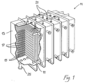
- a crystallizer 11 for static crystallization as shown in FIG. a container 13 for receiving the melt or the Gatsches and in this Container 13 a distance from each other a number of coolable and heatable Heat exchanger walls 15, which are enclosed by the Gatsch.
- the Heat exchanger walls 15 have one inside Heat transfer medium flowable channels 17, with a distribution battery 19 are connected.
- Layered zones 18 are formed by the heat exchangers 15 formed with a constant thickness between the heat exchanger surfaces.
- a melt or a batch is fed into the container 13 via inlets 21 fed where it on the cooled heat exchanger walls 15 in fractions crystallized in layers.
- the one after the solidification of the to be won Fractions remaining liquid phase is discharged through outlets 25, then by heating the heat exchanger walls in the crystals existing fractions and residual amounts of undesirable substances sweaty and also drained, to finally get through this Process to purify crystallized material separately and collect it.
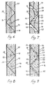
- FIGS Figures 2 and 5 An embodiment 27 of the crystallizer according to the invention is shown in FIGS Figures 2 and 5 are shown in simplified form. Between the heat exchanger walls 15 Permeable structures 29 are arranged in the interior of the container 13. This Structures are made from perforated sheets 31 (FIGS. 3 and 4). The perforation 33 of the Perforated plates 31 serve for the permeability of the structures 29 for the liquid phase. The perforated plate 31 is folded in a zigzag, so that adjacent edges 37 Touch opposite heat exchanger surfaces 39. The edges 37 run practically horizontal ( Figure 5). A row of holes 35 is on the perforated plate edge 37 arranged so that even in the deepest areas of the triangular Zones 41 the liquid phase can run off.
- a paraffin-containing melt is now deoiled in this crystallizer 27, it forms as shown in Figures 6 to 9, on the cooled Heat exchanger surfaces 39 a paraffin layer 43.
- an intermediate space 45 over which the liquid fractions - which have a high oil content - be drained, or the two layers 43 grow together into a single layer 44, with between the Layers of inclusions 46 of liquid fractions and oils are possible (FIG. 8 and 9).
- the remaining liquid components are now as far as possible drained.
- the oily or low-melting fractions through the surfaces 47, 49, 57 of the Paraffin layers 43 sweated out.
- the surface 49 on the heat exchanger side Paraffin pieces 53 can be melted by the supply of heat, so that the liquid phase finds 55 channels or these between Heat exchanger surface 39 and paraffin layer 43 melt free and through the Openings 35 on the edges 37 of the heat exchanger surfaces 39 touching Drain off perforated plates 31. Liquid fractions and oils 55 on paraffin pieces 53 fall, run over the inclined surface 57 of the fixed attachment or Paraffin piece 53 and drip through holes 33 in the perforated plate 31 in the next lower triangular zone 41. After the sweating phase the Fixed batch 53 melted in fractions.
Abstract
Description
Die vorliegende Erfindung betrifft ein Verfahren zur Gewinnung Von Paraffinen oder Paraffinfraktionen aus einer paraffinhaltigen Schmelze, insbesondere aus Gatsch oder einem unterschiedliche Paraffinfraktionen aufweisenden Gemisch, bei welchem verfahren in einem mit Wärmetauschern ausgestatteten Behälter die Schmelze auf eine Temperatur unter der Schmelztemperatur der zu gewinnenden Paraffinfraktionen abgekühlt wird und flüssige niedrigschmelzende Fraktionen und Öle von durch die Abkühlung verfestigten höherschmelzenden Paraffinfraktionen abgetrennt und abgeleitet werden. The present invention relates to a method for obtaining paraffins or paraffin fractions from a paraffin-containing melt, in particular from Gatsch or a mixture containing different paraffin fractions, in which process the melt is cooled to a temperature below the melting temperature of the paraffin fractions to be obtained in a container equipped with heat exchangers and liquid low-melting fractions and oils are separated from higher-melting paraffin fractions solidified by cooling.
Paraffine sind bei Raumtemperatur feste Kohlenwasserstoffe, die aus gesättigten geraden, verzweigten und/oder ringförmigen Kohlenwasserstoffketten bestehen. Mineralölbasische Paraffine weisen etwa 20 bis 50 C-Atome, andere, insbesondere synthetische Paraffine bis zu etwa 100 C-Atome auf. Aufgrund ihrer Herkunft, z.B. aus Mineralölen unterschiedlicher Siedelagen, ist die Anzahl der C-Atome und ihr Verzweigungsgrad sehr unterschiedlich. Man unterscheidet die Paraffine nach der Erstarrungstemperatur grob zwischen tiefschmelzenden Weichparaffinen mit einem Erstarrungspunkt (Ep) zwischen ungefähr 30 und 48°C und höherschmelzenden Hartparaffinen mit einem Erstarrungspunkt zwischen ungefähr 50 und 65 °C. Weiter werden zu den Paraffinen mikrokristalline Paraffine (Mikrowachse) aus Destillationsrückständen oder schweren Destillaten paraffinbasischer Rohöle gezählt. Paraffins are hydrocarbons that are solid at room temperature and consist of saturated straight, branched and / or ring-shaped hydrocarbon chains. Mineral oil-based paraffins have about 20 to 50 carbon atoms, other, especially synthetic paraffins up to about 100 carbon atoms. Due to their origin, e.g. from mineral oils from different settlements, the number of carbon atoms and their degree of branching are very different. A distinction is made between the paraffins according to the solidification temperature between deep-melting soft paraffins with a solidification point (Ep) between approximately 30 and 48 ° C and higher-melting hard paraffins with a solidification point between approximately 50 and 65 ° C. The paraffins also include microcrystalline paraffins (microwaxes) from distillation residues or heavy distillates of paraffin-based crude oils.
Die Paraffinsorten sind im Allgemeinen umso wertvoller, je höher ihr Schmelzpunkt liegt. Abhängig von ihrer Reinheit und ihrem Erstarrungspunkt werden Paraffine sehr vielseitig eingesetzt, insbesondere in der Kerzen-, Papier-, Gummi-, Verpackungs-, Textil- und Lebensmittelindustrie. Weiter werden sie auch zur Herstellung von Pflege- und Poliermitteln, kosmetischen und pharmazeutischen Produkten sowie als Latentwärmespeichermaterial verwendet. The types of paraffin are generally more valuable the higher their melting point lies. Depending on their purity and their solidification point, paraffins very versatile, especially in candle, paper, rubber, Packaging, textile and food industries. They also become Manufacture of care and polishing agents, cosmetic and pharmaceutical Products as well as used as latent heat storage material.
Ausgangspunkt für die Herstellung von Paraffinen sind die in Erdölraffinerien als Nebenprodukt der Schmierölproduktion anfallenden Paraffingatsche, welche unterschiedliche Anteile flüssiger Komponenten aufweisen, aber auch durch thermische Degradation von Kunststoffen gewonnene feste Paraffinfraktionen. Der Gesamtanteil bei Raumtemperatur flüssiger Komponenten im Paraffin oder Paraffingatsch wird als Ölgehalt bezeichnet. Für das Fertigprodukt Paraffin wird je nach benötigter Qualität in der Regel ein maximaler Ölgehalt von 0,5 bis 1,5 Gewichtsprozent gefordert. Beim Fertigprodukt mit höchsten 0,5 Gewichtsprozent Ölgehalt gelten als zusätzliche Qualitätsmerkmale der Erstarrungspunkt und der Nadelpenetrationswert.The starting point for the production of paraffins are those in oil refineries as A by-product of the paraffin grease produced by the lubricating oil production, which have different proportions of liquid components, but also by Thermal degradation of solid paraffin fractions obtained from plastics. Of the Total proportion of components in paraffin or liquid at room temperature Paraffin gums are referred to as oil content. For the finished product, paraffin is used depending on the quality required, a maximum oil content of 0.5 to 1.5 as a rule Weight percent required. In the finished product with a maximum of 0.5 percent by weight Oil content are additional quality features of the freezing point and the Needle penetration value.
Um Paraffin hoher Qualität aus den in Raffinerien anfallenden paraffinhaltigen Fraktionen zu erhalten, sind grosstechnisch zwei grundsätzlich unterschiedliche Arten der Entölung bekannt, nämlich die ältere Schwitzentölung und die jüngere, effizientere Lösemittelentölung.In order to obtain high quality paraffin from the paraffin-containing fractions obtained in refineries, two fundamentally different types of deoiling are known on an industrial scale, namely the older sweat deoiling and the younger, more efficient solvent deoiling.
1959 wird in Asinger, F., "Chemie und Technologie der
Paraffinkohlenwasserstoffe, 1. Auflage, Berlin, auf der Seite 46 zur
Schwitsentölung bemerkt:
"Der Schwitzprozess ist in der Praxis schwierig zu leiten und dürfte in Zukunft
durch die Lösemittel-Entölung abgelöst werden."
Tatsächlich ist man wegen der gravierenden Nachteile der Schwitzentölung von
ihr abgekommen und verwendet heute vorwiegend Lösemittelverfahren. Gemäss
"Ullmanns Enzyklopädie der technischen Chemie", Band 24, Seite 26, werden in
den USA über 90% der bestehenden Anlagen nach dem Prinzip der
Lösemittelentölung betrieben. Seit einiger Zeit werden auch keine neuen
Schwitzentölungsanlagen mehr gebaut.1959 in Asinger, F., "Chemistry and technology of paraffin hydrocarbons, 1st edition, Berlin, on
"In practice, the sweating process is difficult to manage and should be replaced by solvent deoiling in the future."
In fact, because of the serious disadvantages of sweating, sweating has been abandoned and today mainly solvent processes are used. According to "Ullmann's Encyclopedia of Technical Chemistry", volume 24, page 26, over 90% of the existing systems in the USA are operated on the principle of solvent deoiling. For some time now, no new sweat oil removal systems have been built.
Die Lösemittelentölungsverfahren, auch Solvententölung oder Selektiventölung
genannt, sind kontinuierliche Verfahren, mit denen aus allen paraffinhaltigen
Schmelzen die Paraffine gewonnen und in Fraktionen zerlegt werden können. Sie
verwenden Lösemittel für die Trennung von Paraffinen und Ölanteilen und
gewährleisten eine bessere Paraffinausbeute als die Schwitzentölung.
Lösemittelentölungen zeichnen sich durch eine hohe Flexibilität beim Einsatz
unterschiedlicher Gatschqualitäten aus, indem mit der
Lösemittelzusammensetzung und dem Gatsch/Lösemittel-Verhältnis auf die
unterschiedlichen Gatsche eingegangen werden kann. Es werden folgende
Verfahren bei der Lösemittelentölung angewendet:
Die Problematik aller Lösemittelverfahren liegt in den umweltgefährdenden und gesundheitsschädigenden Eigenschaften der in grossen Mengen verwendeten Lösemittel (3 bis 10 Anteile Lösemittel auf einen Anteil Gatsch) sowie deren Korrosivität und leichte Entzündbarkeit. Zudem fällt ein hoher Energieaufwand für die Lösemittelrückgewinnung und die den Prozess begünstigende Kühlung an. Trotz diesen Problemen und Kostenfaktoren hat sich die Lösemittelentölung heute gegen die Schwitzentölung durchgesetzt, weil sie gegenüber der Schwitzentölung eine höhere Paraffinausbeute bei gleichzeitig grösserer Leistung der Anlage gewährleistet und weil damit auch paraffinhaltige Schmelzen mit einem höheren Anteil an mikrokristallinen Paraffinen entölt werden können. The problem with all solvent processes lies in the environmentally hazardous and health-damaging properties of the solvents used in large quantities (3 to 10 parts of solvent per part of Gatsch) as well as their corrosiveness and easy flammability. In addition, there is a high energy expenditure for solvent recovery and cooling that favors the process. Despite these problems and cost factors, solvent de-oiling has now prevailed against sweat de-oiling because it guarantees a higher paraffin yield compared to sweat de-oiling and at the same time greater performance of the system, and because it can also be used to de-oil paraffin-containing melts with a higher proportion of microcrystalline paraffins.
Die Schwitzentölung ist das bis anhin einzige bekannte, grosstechnisch je angewendete Verfahren zur praktisch lösemittelfreien Entölung von Paraffin. Diese Eigenschaft der Schwitzentölung ist aus ökologischen Überlegungen heraus sehr zu begrüssen und wirkt sich auch auf die Anlage-, Instandhaltungs- und Bertriebskosten positiv aus. Zur Durchführung des Verfahrens werden Kammern verwendet, welche mit horizontal angeordneten Wärmetauscherspiralen oder aber mit vertikalen Wärmetauscher-Rohrbündeln und waagrechten Siebböden ausgestattet sind. In diese Kammern oder Behälter wird zuerst eine Wasservorgabe gefüllt, damit die Abläufe nicht verstopft werden, dann wird das geschmolzene Rohparaffin (der Paraffingatsch) in die Kammern gefüllt. Der Paraffingatsch schwimmt auf der Wasservorgabe. Dann lässt man das Rohparaffin unter Kühlen zu einem Block erstatten und anschliessend kann die Wasservorgabe unter dem festen, auf Wärmetauscherleitungen und/oder siebförmigen Zwischenböden ruhenden Block abgelassen werden. Während dieser Block anschliessend langsam erwärmt wird, schwitzt das Öl, und bei höherer Temperatur auch tiefschmelzende Weichparaffine, aus dem Paraffinblock aus. Die ablaufende flüssige Phase wird Ablauföl genannt. Sie kann aufgrund von Lösungsgleichgewichten hohe Anteile der an sich zu gewinnenden höherschmelzenden Paraffinanteile enthalten.The Schwitzentölung is so far only known industrially per method used for virtually solvent-free extraction of oil from paraffin. This property of sweat removal is very much to be welcomed for ecological reasons and also has a positive effect on the plant, maintenance and operating costs. To carry out the process, chambers are used which are equipped with horizontally arranged heat exchanger spirals or with vertical heat exchanger tube bundles and horizontal sieve plates. A water supply is first filled into these chambers or containers so that the processes are not clogged, then the melted raw paraffin (the paraffin wax) is filled into the chambers. The paraffin gossip floats on the water specification. The raw paraffin is then allowed to cool to a block and then the water supply can be drained off under the fixed block resting on heat exchanger pipes and / or sieve-shaped intermediate floors. While this block is then slowly warmed up, the oil, and at higher temperatures also deep-melting soft paraffins, sweat out of the paraffin block. The flowing liquid phase is called drain oil. Due to solution equilibria, it can contain high proportions of the higher-melting paraffin contents to be obtained.
In "Ullmanns Enzyklopädie der technischen Chemie", Band 24, Seite 26, sind die
Nachteile der Schwitzentölung wie folgt beschrieben:
"Für dieses klassische Entölungsverfahren werden wegen der geringen
Selektivität (schlechtere Hartparaffinausbeuten), dem zeitaufwendigen Erwärmen,
der diskontinuierlichen Fahrweise und der Nichtanwendbarkeit bei stark
ölbindenen Rohparaffinen aus schweren Machinenöldestillaten keine Neuanlagen
mehr gebaut. Bei den noch bestehenden Anlagen versucht man, durch partielle
Rückführung der Ablauföle die Hartparaffin-Ausbeute zu verbessern."In "Ullmann's Encyclopedia of Technical Chemistry", volume 24, page 26, the disadvantages of sweating are described as follows:
"Because of the low selectivity (poorer hard paraffin yields), the time-consuming heating, the discontinuous procedure and the inapplicability in the case of strongly oil-binding raw paraffins made from heavy machine oil distillates, no new systems are built for this classic oil removal process. In the still existing systems, attempts are made to partially recycle the waste oils to improve the hard paraffin yield. "
Es ist deshalb Aufgabe der Erfindung ein wirtschaftliches Verfahren bereitzustellen, mit welchem ohne Zuführen von Lösemitteln eine hohe Ausbeute von hochwertigem Paraffin aus dem Paraffingatsch erreicht wird. It is therefore an object of the invention to provide an economical process by means of which a high yield of high-quality paraffin from the paraffin wax is achieved without the addition of solvents.
Erfindungsgemäss wird dies dadurch erreicht, dass die Temperatur der Wärmetauscherflächen während des Abkühlens der vorerst noch flüssigen Schmelze höher gewählt wird als die Schmelztemperatur eines wesentlichen Teils abzuleitender niedrigschmelzender Fraktionen und Öle, und dass nach der Bildung eines Festansatzes an den Wärmetauscherflächen aus höherschmelzenden Fraktionen die flüssig verbliebenen niedrigschmelzenden Fraktionen und Öle aus dem Behälter abgeleitet werden.According to the invention, this is achieved in that the temperature of the heat exchanger surfaces is selected to be higher than the melting temperature of an essential part of the low-melting fractions and oils to be discharged during the cooling of the initially still liquid melt, and that after the formation of a solid deposit on the heat exchanger surfaces from higher-melting fractions, the liquid remains low-melting fractions and oils are derived from the container.
Durch den Verzicht auf Lösemittel, werden die nachstehenden Vorteile der
Schwitzentölung gegenüber der Lösemittelentölung auch bei dem
erfindungsgemässen Verfahren genutzt:
Dadurch, dass die Kühltemperatur zum Abkühlen der flüssigen Schmelze und dadurch verfestigen der Fraktionen in absteigender Folge, von den höherschmelzenden zu den niedrigschmelzenden Fraktionen und allenfalls Ölen, höher gewählt wird als ein wesentlicher Teil der zur Ableitung bestimmten niedrigschmelzenden Fraktionen und Öle, werden im Wesentlichen nur diese Fraktionen verfestigt, die aus der Schmelze gewonnen werden. Die niedrigschmelzenden Fraktionen und Öle verbleiben flüssig. Daher muss zuerst in der Kühlphase und auch später in der Schwitzphase weniger Energie aufgewendet werden als bei der Schwitzentölung, bei welcher zuerst alle Fraktionen und Öle verfestigt werden und dieser Block anschliessend wieder auf die Schwitztemperatur aufgewärmt werden muss.The fact that the cooling temperature for cooling the liquid melt and thereby solidifying the fractions in descending order from the higher melting to the lower melting fractions and possibly oils, is chosen higher than an essential part of those intended for derivation low-melting fractions and oils, essentially only these Fractions solidified, which are obtained from the melt. The low-melting fractions and oils remain liquid. Therefore, first in less energy in the cooling phase and later in the sweating phase than in sweating, in which all fractions and oils first be solidified and then this block back on the Sweat temperature must be warmed up.
Vorteilhaft werden die sich verfestigenden Fraktionen in Schichten auf im Wesentlichen vertikalen oder geneigten Wärmetauscherflächen aus der Schmelze ausgeschieden. Dadurch können flüssige Fraktionen und Öle unter Nutzung der Schwerkraft ablaufen, ohne dass die Wärmetauscherflächen oder der Festansatz dabei wesentlich hinderlich sind.The solidifying fractions are advantageous in layers on im Substantially vertical or inclined heat exchanger surfaces from the melt eliminated. This allows liquid fractions and oils to be used using the Gravity run off without the heat exchanger surfaces or the fixed attachment are a major hindrance.
Vorteilhaft werden die Schichten auf im Wesentlichen ebenflächigen Wärmetauscherflächen ausgeschieden. Solche Wärmetauscherflächen können so nebeneinander angeordnet werden, dass die dazwischen eingefüllte Schmelze kleine Maximalabstände zur Wärmetauscherfläche aufweist, dass der Behälter durchgehend lediglich Zonen mit solchen Maximalabständen aufweist und dass ein günstiges Verhältnis von Wärmetauscherflächen zu Volumen der Schmelze erreicht wird. Zudem sind die ebenflächigen Zonen zwischen den Wärmetauscherflächen mit einfachen Mittel gliederbar.The layers on essentially flat surfaces are advantageous Excreted heat exchanger surfaces. Such heat exchanger surfaces can arranged side by side that the melt filled in between has small maximum distances to the heat exchanger surface that the container consistently has only zones with such maximum distances and that a favorable ratio of heat exchanger areas to volume of the melt is achieved. In addition, the flat zones between the Heat exchanger surfaces can be structured with simple means.
Vorteilhaft wird, wenn durch Erwärmen von durch die Abkühlung verfestigten Fraktionen niedrigschmelzende Fraktionen und Öle aus dem Festansatz ausgetrieben werden, der verbleibende Festansatz unter Nutzung seines Eigengewichts auf eine Wärmetauscherfläche zugetrieben. Dadurch bleibt der Festansatz in thermischem Kontakt mit der Wärmetauscherfläche und die Temperatur des Festansatzes kann so präziser gesteuert werden. Vorteilhaft wird der verbleibende Festansatz im Zuge der Erwärmung in voneinander gesonderte Streifen aufgelöst, wodurch sich die Oberfläche des Festansatzes vergrössert und über diese vergfösserte Oberfläche geschwitzt werden kann.It is advantageous if solidified by heating by cooling Fractions low-melting fractions and oils from the fixed batch be expelled, the remaining fixed rate using his Own weight driven to a heat exchanger surface. This keeps the Fixed approach in thermal contact with the heat exchanger surface and the The temperature of the fixed batch can thus be controlled more precisely. Will be beneficial the remaining fixed amount in the course of heating in separate from each other Strip dissolved, which increases the surface of the fixed base and can sweat over this enlarged surface.
In der Praxis hat sich als zweckmässig erwiesen, dass der verbleibende Festansatz von den Wärmetauscherflächen wenigstens teilweise auf Leitelemente abgelöst wird, welche den Wärmetauscherflächen zugeneigt sind. Dadurch wird eine Vergrösserung der Oberfläche des Festansatzes und die Nachführung an die Wärmetauscherflächen durch ein Rutschen auf der Leitfläche erreicht. Zweckmässigerweise werden die Schichten durch Erwärmen der Wärmetauscherflächen (39) von diesen gelöst.In practice it has proven to be useful that the remaining Fixed approach from the heat exchanger surfaces at least partially on guide elements is replaced, which are inclined to the heat exchanger surfaces. This will an enlargement of the surface of the fixed approach and the tracking to the Heat exchanger surfaces achieved by sliding on the guide surface. The layers are expediently heated by heating the Heat exchanger surfaces (39) detached from these.
Vorteilhaft werden die durch Erwärmen des Festansatzes ausgetriebenen Bestandteile teilweise durch besondere Leitwege im Leitelement nach unten abgeleitet. Dazu ist das Leitelement perforiert oder weist Kanäle auf, durch die die flüssigen Fraktionen und/oder Öle abtropfen können. Zweckmässigerweise werden die Schichten durch die Leitelemente in Streifen aufgeteilt.The expelled by heating the solid approach are advantageous Components partly through special routes down in the guide element derived. For this purpose, the guide element is perforated or has channels through which the can drain liquid fractions and / or oils. Conveniently the layers are divided into strips by the guide elements.
Wenn die Schmelze einen niedrigen Ölgehalt aufweist, werden vorteilhaft die
Schichten (43) in solchen Stärken ausgeschieden, dass ihre Haftung an den
Wärmetauscherflächen (39) beim Erwärmen ausreicht, sie zu halten. Wo dies
möglich ist, ist eine fraktionierte Kristallisation ohne Leitelemente effizienter als
eine solche mit entsprechenden Elementen. Vorteilhaft werden deshalb die stark
ölhaltigen Schmelzen zuerst mit einem vorgängig beschriebenen Verfahren mit
einer durchlässigen Struktur zwischen den Wärmetauscherflächen entölt, um
danach die dadurch wenigstens teilweise entölten Fraktionen und Gemische in an
den Wärmetauscherflächen haftenden Schichtstärken auszuscheiden. Ebenso ist
es zweckmässig, abgelassene tiefschmelzende Fraktionen und/oder Öle erneut
einem Verfahren nach einem der Ansprüche 1 bis 9 zu unterziehen. Durch diese
Massnahmen werden höhere Ausbeuten und eine höhere Reinheit der gewonnen
Produkte erreicht. Letzteres wird auch durch ein fraktioniertes Abschmelzen des
Festansatzes erreicht.If the melt has a low oil content, the
Layers (43) excreted in such strengths that their adhesion to the
Heat exchanger surfaces (39) is sufficient to keep them warm. Where this
fractional crystallization without guide elements is more efficient than
one with corresponding elements. Therefore, they are advantageous
oily melts first using a previously described method
a permeable structure between the heat exchanger surfaces deoiled in order
then the fractions and mixtures in at least partially deoiled thereby
the layer thicknesses adhering to the heat exchanger surfaces. Likewise
it is advisable to re-drain deep-melting fractions and / or oils
to undergo a method according to any one of
Vorteilhaft wird die Schmelze in einen leeren, mit Wärmetauschern bestückten Behälter eingefüllt. Dadurch fallen zwei Arbeitsschritte bei der Gewinnung von Paraffin weg, nämlich das Einfüllen einer Wasservorgabe und das Ablassen dieser Vorgabe. Es wird zudem eine gegenseitig verunreinigende Berührung von Paraffin und Wasser vermieden.The melt is advantageously in an empty, equipped with heat exchangers Container filled. This involves two steps in the extraction of Paraffin gone, namely filling a water specification and draining this requirement. There is also a mutually contaminating touch of Avoided paraffin and water.
Die Erfindung betrifft auch eine Vorrichtung zur Gewinnung von Paraffinen oder Paraffinfraktionen aus einer paraffinhaltigen Schmelze, bestehend aus einem mit Wärmetauschern ausgestatteten Behälter, wobei die Wärmetauscher im Wesentlichen vertikal ausgerichtete Wärmetauscherflächen aufweisen, zur Trennung von durch Kühlen der Schmelze sich an den Wärmetauscherflächen als Festansatz ahscheidenden höherschmelzenden Paraffinfraktionen von durch Erwärmen aus dem Festansatz austreibbaren niedrigschmelzenden Fraktionen und Ölen. Im erfindungsgemässen Kristallisator, bzw. der erfindungsgemässen Vorrichtung, ist zwischen den Wärmetauscherflächen eine für flüssige Bestandteile durchlässige Struktur angeordnet, welche ein Abrutschen des Festansatzes während des Erwärmens verhindert, wodurch auch abrutschende Festansätze geschwitzt werden können. Bevorzugt sind die Wärmetauscherflächen im Wesentlichen ebenflächig, damit die zwischen den Wärmetauscherflächen sich ergebenden Zonen leicht durch durchlässige Strukturen zu gliedern sind. Weil die Paraffinschichten geneigt oder bevorzugt vertikal angeordnet sind, finden die ausgeschwitzten Fraktionen und Öle an der Oberfläche der Schicht, d.h. an den Grenzflächen zwischen Paraffinschicht und Wärmetauscherfläche und allenfalls zwischen zwei Paraffinschichten, Raum und Gelegenheit zum Abfliessen. Es können keine Öllachen mehr liegen bleiben, da sich keine waagrechte Schichtung bilden kann. Dies verkürzt die notwendigen Stufenzeiten Die durchlässigen Strukturen können siebartige, bürstenartige, gitter- oder raumgitterartige Strukturen sein. Die durchlässigen Strukturen lassen einerseits die Ablauföle oder die flüssigen Anteile des Gatsches durch, halten aber das feste Paraffin an seinem Ort. Sie erlauben eine fraktionierte Kristallisation in statischen Plattenkristallisatoren auch von Gatschen mit einem Ölanteil von über 15 Gewichtsprozenten.The invention also relates to a device for the production of paraffins or Paraffin fractions from a paraffin-containing melt, consisting of a with Heat exchangers equipped container, the heat exchanger in the Have essentially vertically aligned heat exchanger surfaces for Separation by cooling the melt itself on the heat exchanger surfaces Fixed approach of high-melting paraffin fractions from through Heating low-melting fractions which can be driven off from the fixed batch and oils. In the crystallizer according to the invention, or the one according to the invention Device between the heat exchanger surfaces is one for liquid Components permeable structure arranged, which prevents the Fixed approach prevented during heating, which also prevents slipping Fixed approaches can be sweated. Those are preferred Heat exchanger surfaces essentially flat so that the between the Heat exchanger surfaces resulting zones easily through permeable Structures are to be structured. Because the paraffin layers are inclined or preferred the sweat fractions and oils are arranged vertically on the Surface of the layer, i.e. at the interfaces between the paraffin layer and Heat exchanger surface and possibly between two paraffin layers, room and Opportunity to drain. There can be no more oil puddles left there no horizontal stratification can form. This shortens the necessary ones Step times The permeable structures can be sieve-like, brush-like, be lattice or space lattice-like structures. Let the permeable structures on the one hand, the drain oils or the liquid components of the gatch hold out but the solid paraffin in place. They allow a fractional Crystallization in static plate crystallizers also from Gatschen with one Oil content of over 15 percent by weight.
Vorteilhaft weisen solche Strukturen Leitelemente auf, deren Neigungswinkel so gewählt ist, dass sich während der Erwärmung eine selbsttätige Nachführung des Festansatzes an eine Wärmetauscherfläche durch das Eigengewicht des Festansatztes einstellt. Durch die Nachführung bleibt der Festansatz in thermischem Kontakt mit der Wärmetauscherfläche. Vorteilhaft steht eine solche durchlässige Struktur in thermischem Kontakt mit den Wärmetauscherflächen, damit insbesondere in der Schmelzphase die Wärmeübertragung von den Wärmetauscherflächen auf den von den Wärmetauscherflächen gelösten, auf der durchlässigen Struktur liegenden Festansatz optimal ist.Such structures advantageously have guide elements whose inclination angles are so is chosen that an automatic tracking of the Fixed approach to a heat exchanger surface by the weight of the Sets firm approaches. Due to the tracking, the fixed approach remains in thermal contact with the heat exchanger surface. Such is advantageous permeable structure in thermal contact with the heat exchanger surfaces, thus especially in the melting phase the heat transfer from the Heat exchanger surfaces on those detached from the heat exchanger surfaces on the permeable structure lying fixed approach is optimal.
Vorteilhaft sind die Leitelemente den Raum zwischen den Wärmetauscherflächen etwa horizontal gliedernde, geneigte Flächen, und bevorzugt übereinander angeordnete geneigte Flächen gegenläufig geneigt. Solche Flächen sind sehr einfach herstellbar und einbaubar, unterteilen die Schicht des Festansatzes in horizontale Streifen entlang den Wärmetauscherflächen mit vergrösserter schwitzfähiger Oberfläche und können aus verschiedensten Materialien und mit unterschiedlichster Prägung, Lochung oder Stanzung gefertigt werden. Diese Flächen dienen als Leitelemente mit nachführenden Eigenschaften. Die gegenläufige Neigung bewirkt eine gleichmässige, beidseitige Nachführung des Festansatzes gegen die Wärmetauscherflächen.The guide elements are advantageously the space between the heat exchanger surfaces about horizontally structured, inclined surfaces, and preferably one above the other arranged inclined surfaces inclined in opposite directions. Such areas are very easy to manufacture and install, divide the layer of the fixed approach into horizontal stripes along the heat exchanger surfaces with enlarged sweatable surface and can be made of different materials and with different embossing, perforation or punching can be manufactured. This Surfaces serve as guiding elements with tracking properties. The opposite inclination causes an even, bilateral tracking of the Fixed approach against the heat exchanger surfaces.
Vorzugsweise ist die durchlässige Struktur in Einbaueinheiten zusammengefasst, welche zwischen zwei Kristallisationsflächen eingebaut werden können. Sie ist dadurch einfach herstellbar und einbaubar. Vorzugsweise ist die siebartige Struktur durch ein mehrfach zickzackförmig abgekantetes Metallelement gebildet. Metall bietet die notwendige Wärmeleitfähigkeit und die vorteilhafte einfache Bearbeitbarkeit. Die Zickzackform ist durch Biegen des Elements leicht herstellbar und weist die bevorzugten Eigenschaften auf, wie sie oben beschrieben wurden. Das Metallelement kann ein abgekantetes Lochblech, aber auch ein Stabgitter oder ein Netz oder dergleichen sein. Lochbleche gibt es im Handel in einer grossen Vielfalt von verschiedenen Lochungen. Vorteilhaft wird ein Perforationsmuster gewählt, bei welchem das Muster derart ineinander greift, dass bei jeder möglichen Anordnung der Faltlinie, diese durch Öffnungen in der durchlässigen Struktur verläuft.The permeable structure is preferably combined in installation units, which can be installed between two crystallization surfaces. she is therefore easy to manufacture and install. Preferably the sieve is Structure formed by a multiple zigzag folded metal element. Metal offers the necessary thermal conductivity and the advantageous simple Editability. The zigzag shape is easy to manufacture by bending the element and has the preferred properties as described above. The metal element can be a perforated sheet, but also a bar grid or be a network or the like. There are perforated sheets in one in the trade wide variety of different perforations. One will be advantageous Perforation pattern chosen, in which the pattern interlocks in such a way that with every possible arrangement of the fold line, this through openings in the permeable structure.
Es kann auch zweckmässig sein, dass die für flüssige Fraktionen und Öle durchlässige Struktur durch die Wärmetauscherflächen selbst gebildet ist. Dadurch ist ein besserer Wärmeübergang zwischen dem Wärmetransfermedium und der durchlässigen Struktur und dadurch der Schmelze bzw. dem Festansatz gewährleistet, als wenn die Wärmetauscherflächen und die durchlässige Struktur zwei voneinander unabhängige Teile sind.It may also be appropriate for liquid fractions and oils permeable structure is formed by the heat exchanger surfaces themselves. This is a better heat transfer between the heat transfer medium and the permeable structure and thereby the melt or the solid approach ensures as if the heat exchanger surfaces and the permeable structure are two independent parts.
Vorteilhaft unterteilen die Wärmetauscher den Behälter in Raumzonen, welche so dimensioniert sind, dass im Behälter befindliche Schmelze durchgehend einen kleinen Abstand zur nächstliegenden Wärmetauscherfläche aufweist. Dadurch erübrigt sich eine Wasservorgabe, denn der gesamte Raum des Behälters ist in engem Einflussbereich der Wärmetauscherflächen. Auch ist das Verhältnis zwischen Wärmetauscherflächen und Volumen der Schmelze günstig für eine präzises und rasches Kühlen und Heizen.The heat exchangers advantageously divide the container into room zones, which are so are dimensioned so that the melt in the container is continuous has a small distance from the nearest heat exchanger surface. Thereby there is no need for a water specification because the entire space of the container is in narrow area of influence of the heat exchanger surfaces. The relationship is also between heat exchanger surfaces and volume of the melt cheap for one precise and rapid cooling and heating.
Die notwendigen Batch-Zeiten oder Stufenzeiten können in einer solchen Anlage
von bisher 30 bis 40 Stunden signifikant verkürzt werden. Dadurch ist
Das erfindungsgemässe Verfahren weist gegenüber dem Schwitzverfahren zudem
folgende Vorteile auf:
Bemerkenswert ist die auch gegenüber der Lösemittelentölung erhöhte Ausbeute von Paraffinen in der geforderten Qualität.The increased yield compared to solvent deoiling is remarkable of paraffins in the required quality.
Zweckmässigerweise wird das erfindungsgemässe Verfahren sowohl zur Gewinnung und Reinigung von Paraffinen und Paraffinfraktionen aus Mineralölgatschen als auch aus paraffinhaltigen Schmelzen synthetischen Ursprungs (Fischer-Tropsch-Synthese) oder aus durch thermischen Abbau von Kunststoffen gewonnenen Schmelzen (Recyclat-Paraffine) verwendet. Das Verfahren wird zweckmässigerweise auch auf entsprechende Gemische angewendet.The method according to the invention is expediently used both for Extraction and purification of paraffins and paraffin fractions Mineral oil creels as well as synthetic paraffin-containing melts Origin (Fischer-Tropsch synthesis) or by thermal degradation of Plastics-derived melts (recycled paraffins) are used. The The method is expediently also based on corresponding mixtures applied.
Nachfolgend werden als Beispiele verschiedene Gatsche in drei Tabellen vergleichend dargestellt. Verglichen werden die Resultate des heute gebräuchlichen Lösemittelverfahrens mit den Resultaten der Paffinentölung durch fraktionierte Kristallisation gemäss dem erfindungsgemässen Verfahren (letzte Spalte) und des bekannten Schwitzverfahrens. Die Vergleichswerte sind der Erstarrungspunkt in Grad Celsius nach DIN-ISO 2207, der Ölgehalt in Gewichtsprozenten nach DIN-ISO 2908, der Nadelpenetrationswert bei 25°C in 0,1 mm nach DIN 51 579 und die Ausbeuten:Various gatches in three tables are shown below as examples presented comparably. The results of today are compared common solvent process with the results of waxing fractional crystallization according to the inventive method (last Column) and the known sweating process. The comparison values are the Freezing point in degrees Celsius according to DIN-ISO 2207, the oil content in Percentages by weight according to DIN-ISO 2908, the needle penetration value at 25 ° C in 0.1 mm according to DIN 51 579 and the yields:


Auffällig bei den drei Beispielen sind die deutlich höheren Ausbeuten mit der erfindungsgemässen Kristallisation als mit den beiden Vergleichsverfahren. Während die Werte für den Erstarrungspunkt des Endprodukts beim erfindungsgemässen Kristallisationsverfahren den Werten beim Lösemittelverfahren ähnlich sind (der bessere Wert im Beispiel 1 sei dabei nicht übersehen) und der Ölgehalt bei allen Beispielen keine verfahrensabhängigen Unterschiede aufweist, fällt der Nadelpenetrationswert abhängig von Gatschqualität und angewendetem Verfahren unterschiedlich aus. Die mit dem erfindungsgemässen Verfahren gereinigten Paraffine weisen aber nie einen schlechteren als den geforderten Wert auf. Im Beispiel 2 liegt der Nadelpenetrationswert wie beim Lösemittelverfahren unterhalb der geforderten Limite, und ist damit besser als gefordert. Zusammenfassend kann gesagt werden, dass mit dem erfindungsgemässen Verfahren gegenüber den bekannten Verfahren, bei mindestens gleichwertiger Qualität des Endproduktes, die Ausbeute wesentlich erhöht wird. Das Verfahren weist darüber hinaus weder die wesentlichen Nachteile der Schwitzentölung (lange Batch-Zeiten, geringe Selektivität, Verarbeitung nur von Gatschen mit relativ niedrigem Ölgehalt, schlechte Verwertung der Ablauföle) noch die der Lösemittelentölung (Umwelt- und Gesundheitsgefährdung, hohe Instandhaltungskosten wegen der Anlagenkorrosion, hohe Betriebskosten durch die Lösemittelrückgewinnung und die Kühlung, niederwertige Verwertung der Ablauföle) auf.What is striking in the three examples is the significantly higher yields with the crystallization according to the invention as with the two comparison methods. While the values for the solidification point of the end product at Crystallization process according to the invention the values at Solvent processes are similar (the better value in Example 1 is not overlooked) and the oil content in all examples is not process-dependent Shows differences, the needle penetration value falls depending on Gatch quality and the process used differ. The one with the However, paraffins purified according to the method of the invention never have one worse than the required value. In example 2 the Needle penetration value as in the solvent process below the required Limit, and is therefore better than required. In summary it can be said, that with the inventive method compared to the known Process, with at least equivalent quality of the end product, the yield is significantly increased. Furthermore, the procedure does not indicate either major disadvantages of sweating (long batch times, low Selectivity, processing only gates with relatively low oil content, poor utilization of the drain oils) or that of the solvent deoiling (environmental and Health hazard, high maintenance costs because of Plant corrosion, high operating costs due to solvent recovery and cooling, low-value recycling of the drain oils).
Nachfolgend werden Ausführungsbeispiele der Erfindung unter Bezugnahme auf die Figuren beschrieben. Es zeigt:
- Fig. 1
- einen dem Stand der Technik entsprechenden Kristallisator für die statische Kristallisation, perspektivisch und zum Teil aufgeschnitten dargestellt,
- Fig. 2
- einen schematischen Vertikalschnitt durch einen erfindungsgemäss bestückten Kristallisator,
- Fig. 3
- Detail des Berührungspunktes der Einbaute mit der Kristallisationswandung,
- Fig. 4
- Aufsicht auf die in Figur 3 gezeigte Stelle,
- Fig. 5
- einen schematischen Vertikalschnitt durch einen erfindungsgemässen Kristallisator, relativ zum Schnitt in Fig. 3 um 90 Grad gedreht,
- Fig. 6
- eine mögliche Ausgestaltung der Paraffinschicht nach abgeschlossener Kristallisation,
- Fig. 7
- Paraffinschicht nach Figur 6 während des Schwitzens,
- Fig. 8
- eine weitere mögliche Ausgestaltung der Paraffinschicht nach der abgeschlossenen Kristallisation,
- Fig. 9
- Paraffinschicht nach Figur 8 während des Schwitzens.
- Fig. 1
- a state-of-the-art crystallizer for static crystallization, shown in perspective and partially cut away,
- Fig. 2
- 2 shows a schematic vertical section through a crystallizer equipped according to the invention,
- Fig. 3
- Detail of the point of contact of the installation with the crystallization wall,
- Fig. 4
- Supervision of the point shown in FIG. 3,
- Fig. 5
- 3 shows a schematic vertical section through a crystallizer according to the invention, rotated by 90 degrees relative to the section in FIG. 3,
- Fig. 6
- a possible configuration of the paraffin layer after crystallization is complete,
- Fig. 7
- Paraffin layer according to FIG. 6 during sweating,
- Fig. 8
- a further possible configuration of the paraffin layer after the crystallization has been completed,
- Fig. 9
- Paraffin layer according to Figure 8 during sweating.
Der Übersichtlichkeit wegen werden im folgenden entsprechende Teile unterschiedlicher Kristallisatoren mit der gleichen Bezugsziffer bezeichnet, auch wenn die Ausführungsformen der Teile sich unterscheiden können.For the sake of clarity, corresponding parts are described below different crystallizers with the same reference number, too if the embodiments of the parts can differ.
Ein Kristallisator 11 für die statische Kristallisation weist, wie in Figur 1 dargestellt,
einen Behälter 13 zur Aufnahme der Schmelze oder des Gatsches und in diesem
Behälter 13 mit Abstand zueinander eine Anzahl von kühl- und heizbaren
Wärmetauscherwänden 15 auf, die vom Gatsch umschliessbar sind. Die
Wärmetauscherwände 15 weisen in ihrem Innern von einem
Wärmetransfermedium durchfliessbare Kanäle 17 auf, die mit einer Verteilbatterie
19 verbunden sind. Durch die Wärmetauscher 15 sind schichtförmige Zonen 18
mit einer konstanten Dicke zwischen den Wärmetauscherflächen gebildet.A
Eine Schmelze oder ein Gatsch wird über Einläufe 21 in den Behälter 13
eingespeist, wo er an den gekühlten Wärmetauscherwänden 15 in Fraktionen
schichtformig auskristallisiert. Die nach der Verfestigung der zu gewinnenden
Fraktionen verbleibende flüssige Phase wird über Ausläufe 25 abgelassen,
danach werden durch Erwärmen der Wärmetauscherwände im Kristallisat
vorhandene Fraktionen und Restmengen unerwünschter Substanzen
ausgeschwitzt und ebenfalls abgelassen, um schliesslich das durch dieses
Verfahren reiner gewordene Kristallisat separat abzuschmelzen und aufzufangen. A melt or a batch is fed into the
Eine Ausführungsform 27 des erfindungsgemässen Kristallisators ist in den
Figuren 2 und 5 vereinfacht dargestellt. Zwischen den Wärmetauscherwänden 15
im Innern des Behälters 13 sind durchlässige Strukturen 29 angeordnet. Diese
Strukturen sind aus Lochblechen 31 gefertigt (Figur 3 und 4). Die Lochung 33 der
Lochbleche 31 dient der Durchlässigkeit der Strukturen 29 für die flüssige Phase.
Das Lochblech 31 ist im Zickzack gefaltet, so dass benachbarte Kanten 37
gegenüberliegende Wärmetauscherflächen 39 berühren. Die Kanten 37 verlaufen
praktisch horizontal (Figur 5). Eine Lochreihe 35 ist an der Lochblechkante 37
angeordnet, damit auch in den am tiefsten liegenden Bereichen der dreikantigen
Zonen 41 die flüssige Phase ablaufen kann.An
Wird nun in diesem Kristallisator 27 eine paraffinhaltige Schmelze entölt, so bildet
sich, wie in den Figuren 6 bis 9 dargestellt, auf den gekühlten
Wärmetauscherflächen 39 eine Paraffinschicht 43. Zwischen den beiden
Paraffinschichten 43 bleibt je nach Ausgangsprodukt, bzw. Reinheitsgrad der
Schmelze und darauf abgestellten Mengen abzulassender Flüssigbestandteile,
teilweise ein Zwischenraum 45 offen, über den die flüssigen Fraktionen - welche
einen hohen Ölanteil aufweisen - abgelassen werden, oder die beiden Schichten
43 wachsen zu einer einzigen Schicht 44 zusammen, wobei zwischen den
Schichten Einschlüsse 46 von flüssigen Fraktionen und Ölen möglich sind (Fig. 8
und 9). Die flüssig verbliebenen Bestandteile werden nun soweit möglich
abgelassen. In der Schwitzphase werden zuerst die öligen oder
niedrigschmelzenden Fraktionen durch die Oberflächen 47, 49, 57 der
Paraffinschichten 43 ausgeschwitzt. Sobald die Paraffinschicht 43, 44 durch die
Erwärmung aufgeweicht ist, ist ihre Haftfähigkeit an der Wärmetauscherfläche 39
reduziert. Spätestens, wenn durch die Erwärmung die haftende Oberfläche 49 des
Festansatzes 43 angeschmolzen wird, lösen sich Teile 53 des Festansatzes oder
der Paraffinschicht 43 von der Wärmetauscherfläche 39. Diese Teile 53 bleiben im
in spitzem Winkel auf die Wärmetauscherfläche 39 stossenden Lochblech 31
hängen. Durch die Ablösung von der Wärmetauscherfläche 39 und dem
Lochblech 31 wird die schwitzfähige Oberfläche der Paraffinschicht 43
vergrössert. Die flüssige Phase 55 kann an den Oberflächen 47 und 49 austreten.
Das Austreiben der flüssigen Phase 55 wird zudem durch die Last des
Eigengewichts des Paraffinstückes 53 begünstigt. Die flüssige Phase 55 tropft
zwischen den Paraffinstücken 53 ab. Zum Teil läuft die flüssige Phase 55 entlang
den Wärmetauscherflächen 39 ab. Die wärmetauscherseitige Oberfläche 49 der
Paraffinstücke 53 kann durch die Zufuhr von Wärme angeschmolzen werden, so
dass die flüssige Phase 55 Kanäle findet oder sich diese zwischen
Wärmetauscherfläche 39 und Paraffinschicht 43 freischmilzt und durch die
Öffnungen 35 an den die Wärmetauscherflächen 39 berührenden Kanten 37 der
Lochbleche 31 abfliessen. Flüssige Fraktionen und Öle 55, die auf Paraffinstücke
53 fallen, laufen über die geneigte Oberfläche 57 des Festansatzes oder
Paraffinstücks 53 ab und tropfen durch Löcher 33 im Lochblech 31 hindurch in die
nächstuntere dreikantige Zone 41. Nach Abschluss der Schwitzphase wird der
Festansatz 53 fraktionenweise abgeschmolzen.If a paraffin-containing melt is now deoiled in this
Claims (21)
Priority Applications (17)
| Application Number | Priority Date | Filing Date | Title |
|---|---|---|---|
| EP97810497A EP0892033A1 (en) | 1997-07-16 | 1997-07-16 | Process and device for the production of paraffin and paraffin fractions |
| BRPI9802456-6A BR9802456B1 (en) | 1997-07-16 | 1998-06-15 | apparatus, and process for obtaining paraffins or paraffin fractions. |
| CA002242051A CA2242051A1 (en) | 1997-07-16 | 1998-06-30 | A process and apparatus for obtaining paraffins or paraffin fractions |
| ZA985909A ZA985909B (en) | 1997-07-16 | 1998-07-06 | A process and apparatus for obtaining paraffins or paraffin fractions |
| HU9801515A HUP9801515A3 (en) | 1997-07-16 | 1998-07-07 | Process and apparatus for producing paraffins or paraffin-fractiones |
| SG1998001752A SG65773A1 (en) | 1997-07-16 | 1998-07-10 | A process and apparatus for obtaining paraffins or paraffin fractions |
| IDP981003A ID20590A (en) | 1997-07-16 | 1998-07-14 | PROCESSES AND TOOLS FOR ACQUIRING THE PARAFIN OR THE PARAFIN FACTION |
| MYPI98003206A MY116759A (en) | 1997-07-16 | 1998-07-14 | Process for obtaining paraffin or paraffin fractions. |
| EG82098A EG21593A (en) | 1997-07-16 | 1998-07-14 | A process and apparatus for obtaining paraffins or paraffin fractions |
| CN98115989A CN1085242C (en) | 1997-07-16 | 1998-07-15 | Process and apparatus for obtaining paraffins or paraffin fractions |
| KR1019980028511A KR19990013867A (en) | 1997-07-16 | 1998-07-15 | Method and apparatus for obtaining paraffin or paraffin sorting |
| EA199800572A EA000488B1 (en) | 1997-07-16 | 1998-07-15 | Process and apparatus for obtaining paraffins or paraffin fractions |
| ARP980103456A AR014620A1 (en) | 1997-07-16 | 1998-07-15 | PROCESSES TO OBTAIN PARFINES OR FRACTIONS OF PARFINES. |
| PL98327536A PL189190B1 (en) | 1997-07-16 | 1998-07-16 | Method of obtaining paraffins or their fractions |
| JP20154898A JP4071365B2 (en) | 1997-07-16 | 1998-07-16 | Method and apparatus for obtaining paraffin or paraffin fractions |
| US09/001,186 US6074548A (en) | 1997-07-16 | 1998-07-16 | Process for obtaining paraffin or paraffin fractions |
| SA98190551A SA98190551B1 (en) | 1997-07-16 | 1998-09-15 | A process to obtain paraffin or paraffin fractions |
Applications Claiming Priority (1)
| Application Number | Priority Date | Filing Date | Title |
|---|---|---|---|
| EP97810497A EP0892033A1 (en) | 1997-07-16 | 1997-07-16 | Process and device for the production of paraffin and paraffin fractions |
Publications (1)
| Publication Number | Publication Date |
|---|---|
| EP0892033A1 true EP0892033A1 (en) | 1999-01-20 |
Family
ID=8230308
Family Applications (1)
| Application Number | Title | Priority Date | Filing Date |
|---|---|---|---|
| EP97810497A Withdrawn EP0892033A1 (en) | 1997-07-16 | 1997-07-16 | Process and device for the production of paraffin and paraffin fractions |
Country Status (17)
| Country | Link |
|---|---|
| US (1) | US6074548A (en) |
| EP (1) | EP0892033A1 (en) |
| JP (1) | JP4071365B2 (en) |
| KR (1) | KR19990013867A (en) |
| CN (1) | CN1085242C (en) |
| AR (1) | AR014620A1 (en) |
| BR (1) | BR9802456B1 (en) |
| CA (1) | CA2242051A1 (en) |
| EA (1) | EA000488B1 (en) |
| EG (1) | EG21593A (en) |
| HU (1) | HUP9801515A3 (en) |
| ID (1) | ID20590A (en) |
| MY (1) | MY116759A (en) |
| PL (1) | PL189190B1 (en) |
| SA (1) | SA98190551B1 (en) |
| SG (1) | SG65773A1 (en) |
| ZA (1) | ZA985909B (en) |
Families Citing this family (16)
| Publication number | Priority date | Publication date | Assignee | Title |
|---|---|---|---|---|
| EP1216734A1 (en) * | 2000-12-22 | 2002-06-26 | Sulzer Chemtech AG | Process and crystallizer for the separation of multicomponent mixtures |
| TW200720418A (en) * | 2005-07-18 | 2007-06-01 | Shell Int Research | Process for reducing the cloud point of a base oil |
| US8748516B2 (en) * | 2009-03-31 | 2014-06-10 | Weyerhaeuser Nr Company | Wood composite with water-repelling agent |
| CN102533333B (en) * | 2012-01-16 | 2014-01-08 | 无锡信达胶脂材料有限公司 | Preparation method of paraffin for pharmaceutic adjuvants |
| RU2635357C2 (en) * | 2012-08-02 | 2017-11-13 | Сэсол Текнолоджи (Проприетери ) Лимитед | Wax processing |
| EP3103539A1 (en) * | 2015-06-11 | 2016-12-14 | Sulzer Chemtech AG | Method and apparatus for purifying a mixture comprising oil and wax |
| EP3109296A1 (en) | 2015-06-26 | 2016-12-28 | Sasol Wax GmbH | Process for obtaining wax fractions from a feed wax |
| CN107513405B (en) * | 2016-06-17 | 2019-04-12 | 中国石油化工股份有限公司 | A method of preparing plastic processing wax |
| CN107513423B (en) * | 2016-06-17 | 2019-05-17 | 中国石油化工股份有限公司 | The method for preparing Wax-for preventing rubber |
| CN107513407B (en) * | 2016-06-17 | 2019-04-12 | 中国石油化工股份有限公司 | The method for preparing thermostat Wax dielectric with F-T synthetic product |
| CN107513412B (en) * | 2016-06-17 | 2019-05-21 | 中国石油化工股份有限公司 | The preparation method of soap manufacturing paraffin and low melt point paraffin |
| CN107513409B (en) * | 2016-06-17 | 2019-05-21 | 中国石油化工股份有限公司 | The production method of soap manufacturing paraffin and low melt point paraffin |
| WO2020050369A1 (en) * | 2018-09-07 | 2020-03-12 | Jxtgエネルギー株式会社 | Method for producing wax, wax, and method for producing lubricant base oil |
| CN112007431A (en) * | 2019-05-31 | 2020-12-01 | 江苏国威化工有限公司 | Chlorinated paraffin tail gas pretreatment method and treatment equipment thereof |
| CN112322350B (en) * | 2020-11-05 | 2021-12-07 | 中国科学院山西煤炭化学研究所 | Method for preparing high enthalpy value phase-change wax from Fischer-Tropsch synthesis product |
| CN113372955A (en) * | 2021-07-23 | 2021-09-10 | 上海莱布星科技有限公司 | High-efficiency sweating dish sweating method and device based on high-heat-conduction material |
Citations (4)
| Publication number | Priority date | Publication date | Assignee | Title |
|---|---|---|---|---|
| GB340993A (en) * | 1929-10-02 | 1931-01-02 | Hugh Logie Allan | Improvements in apparatus for the sweating of wax or wax mixtures |
| US3926776A (en) * | 1974-06-28 | 1975-12-16 | Roy E Irwin | Method and apparatus for wax deoiling |
| US4013541A (en) * | 1974-06-28 | 1977-03-22 | Irwin Roy E | Method and apparatus for wax deoiling |
| US5015357A (en) * | 1988-01-04 | 1991-05-14 | Amoco Corporation | Wax sweating |
Family Cites Families (5)
| Publication number | Priority date | Publication date | Assignee | Title |
|---|---|---|---|---|
| SU889027A1 (en) * | 1979-05-08 | 1981-12-15 | Московский Ордена Трудового Красного Знамени Институт Тонкой Химической Технологии Им. В.М.Ломоносова | Fraction melting apparatus |
| US4252549A (en) * | 1979-05-31 | 1981-02-24 | Suntech, Inc. | Crystallization via porous tube heat transfer |
| SU919694A1 (en) * | 1980-07-31 | 1982-04-15 | Московский Ордена Трудового Красного Знамени Институт Тонкой Химической Технологии Им.М.В.Ломоносова | Apparatus for fractional melting |
| EP0494045B1 (en) * | 1990-12-21 | 1995-04-19 | Sulzer Chemtech AG | Process and apparatus for separating matter by means of crystallization |
| RU2046627C1 (en) * | 1994-05-20 | 1995-10-27 | Борис Евсеевич Сельский | Heat-and-mass transfer apparatus |
-
1997
- 1997-07-16 EP EP97810497A patent/EP0892033A1/en not_active Withdrawn
-
1998
- 1998-06-15 BR BRPI9802456-6A patent/BR9802456B1/en not_active IP Right Cessation
- 1998-06-30 CA CA002242051A patent/CA2242051A1/en not_active Abandoned
- 1998-07-06 ZA ZA985909A patent/ZA985909B/en unknown
- 1998-07-07 HU HU9801515A patent/HUP9801515A3/en unknown
- 1998-07-10 SG SG1998001752A patent/SG65773A1/en unknown
- 1998-07-14 ID IDP981003A patent/ID20590A/en unknown
- 1998-07-14 MY MYPI98003206A patent/MY116759A/en unknown
- 1998-07-14 EG EG82098A patent/EG21593A/en active
- 1998-07-15 EA EA199800572A patent/EA000488B1/en not_active IP Right Cessation
- 1998-07-15 KR KR1019980028511A patent/KR19990013867A/en not_active Application Discontinuation
- 1998-07-15 CN CN98115989A patent/CN1085242C/en not_active Expired - Fee Related
- 1998-07-15 AR ARP980103456A patent/AR014620A1/en active IP Right Grant
- 1998-07-16 JP JP20154898A patent/JP4071365B2/en not_active Expired - Fee Related
- 1998-07-16 US US09/001,186 patent/US6074548A/en not_active Expired - Lifetime
- 1998-07-16 PL PL98327536A patent/PL189190B1/en unknown
- 1998-09-15 SA SA98190551A patent/SA98190551B1/en unknown
Patent Citations (4)
| Publication number | Priority date | Publication date | Assignee | Title |
|---|---|---|---|---|
| GB340993A (en) * | 1929-10-02 | 1931-01-02 | Hugh Logie Allan | Improvements in apparatus for the sweating of wax or wax mixtures |
| US3926776A (en) * | 1974-06-28 | 1975-12-16 | Roy E Irwin | Method and apparatus for wax deoiling |
| US4013541A (en) * | 1974-06-28 | 1977-03-22 | Irwin Roy E | Method and apparatus for wax deoiling |
| US5015357A (en) * | 1988-01-04 | 1991-05-14 | Amoco Corporation | Wax sweating |
Also Published As
| Publication number | Publication date |
|---|---|
| MY116759A (en) | 2004-03-31 |
| EA000488B1 (en) | 1999-08-26 |
| US6074548A (en) | 2000-06-13 |
| PL327536A1 (en) | 1999-01-18 |
| SG65773A1 (en) | 1999-06-22 |
| ID20590A (en) | 1999-01-21 |
| EA199800572A1 (en) | 1999-02-25 |
| BR9802456A (en) | 1999-07-20 |
| BR9802456B1 (en) | 2009-01-13 |
| PL189190B1 (en) | 2005-07-29 |
| KR19990013867A (en) | 1999-02-25 |
| AR014620A1 (en) | 2001-03-28 |
| EG21593A (en) | 2001-12-31 |
| ZA985909B (en) | 1999-05-27 |
| HUP9801515A2 (en) | 1999-03-29 |
| HU9801515D0 (en) | 1998-09-28 |
| CN1211609A (en) | 1999-03-24 |
| HUP9801515A3 (en) | 2000-02-28 |
| CA2242051A1 (en) | 1999-01-16 |
| JPH1171585A (en) | 1999-03-16 |
| SA98190551B1 (en) | 2006-10-11 |
| CN1085242C (en) | 2002-05-22 |
| JP4071365B2 (en) | 2008-04-02 |
Similar Documents
| Publication | Publication Date | Title |
|---|---|---|
| EP0892033A1 (en) | Process and device for the production of paraffin and paraffin fractions | |
| DE2607168A1 (en) | METHOD AND DEVICE FOR EXCHANGING HEAT | |
| EP0891798B1 (en) | Process for fractionated crystallising substances, crystallizer siuted to perform the process and use of the crystallizer | |
| DE1519821A1 (en) | Process for the separation of liquid mixtures by crystallization | |
| DE69726041T2 (en) | Process for dry fractionation of oils and fats | |
| DE2063665A1 (en) | DEVICE FOR WATER CLEANING BY FREEZING WITH NON-MIXABLE FREEZING AGENTS | |
| DE1085852B (en) | Device for cleaning crystals | |
| EP2172442B1 (en) | Method and device for separating carboxylic acids and/or carboxylic acid esters | |
| EP0390742A1 (en) | Arrangement and method for the filtration of molten metals | |
| DE2127990B2 (en) | Device for mass and heat transfer between two immiscible, flowable substances | |
| EP0766984B1 (en) | Process for separating substances of a liquid mixture by crystallisation | |
| DE2823124C2 (en) | Process and device for material separation by means of crystallization | |
| EP0379021B1 (en) | Process for working up the raffinate fraction obtained in the extractine distillation of hydrocarbon mixtures | |
| DE2313988A1 (en) | METHOD AND DEVICE FOR CRYSTALLIZATION | |
| DE1418959A1 (en) | Method and apparatus for producing p-xylene | |
| DE60105776T2 (en) | SEPARATION OF 2,4-TOLUOL DIAMINE FROM A MIXTURE OF TOLUOL DIAMINE ISOMERS | |
| DE2528185A1 (en) | PROCESS FOR SEPARATING THE LOW-MELTING FROM THE HIGHER-MELTING COMPONENTS OF A PARAFFIN MIXTURE AND DEVICE FOR ITS PERFORMANCE | |
| EP0054196B1 (en) | Installation for the production of phosphorus pentasulfide | |
| DE2624206A1 (en) | DEPARANCING PROCEDURES | |
| DE2919250C2 (en) | Heat exchanger for the extraction of exothermic heat of crystallization from a liquid | |
| EP0148511B1 (en) | Method of separation of a liquid mixture by fractionated crystallisation | |
| DE1912019B2 (en) | METHOD AND DEVICE FOR FREEZING AQUATIC AND NON-Aqueous SOLUTIONS, COLLOIDAL SOLUTIONS AND SUSPEN SIONS | |
| DE909387C (en) | Process for the processing of solid paraffins obtained in the production of hydrocarbons from carbon oxide and hydrogen according to Fischer-Tropsch | |
| DE307625C (en) | ||
| DE2119271C2 (en) | Process for dewaxing and de-oiling petroleum fractions containing paraffin |
Legal Events
| Date | Code | Title | Description |
|---|---|---|---|
| PUAI | Public reference made under article 153(3) epc to a published international application that has entered the european phase |
Free format text: ORIGINAL CODE: 0009012 |
|
| AK | Designated contracting states |
Kind code of ref document: A1 Designated state(s): BE CH DE ES FR GB GR IT LI NL |
|
| AX | Request for extension of the european patent |
Free format text: AL;LT;LV;RO;SI |
|
| 17P | Request for examination filed |
Effective date: 19990608 |
|
| AKX | Designation fees paid |
Free format text: BE CH DE ES FR GB GR IT LI NL |
|
| 17Q | First examination report despatched |
Effective date: 19990903 |
|
| STAA | Information on the status of an ep patent application or granted ep patent |
Free format text: STATUS: THE APPLICATION HAS BEEN WITHDRAWN |
|
| 18W | Application withdrawn |
Withdrawal date: 20020128 |