EP0891916A1 - Front sub-frame for a motor vehicle - Google Patents
Front sub-frame for a motor vehicle Download PDFInfo
- Publication number
- EP0891916A1 EP0891916A1 EP98401786A EP98401786A EP0891916A1 EP 0891916 A1 EP0891916 A1 EP 0891916A1 EP 98401786 A EP98401786 A EP 98401786A EP 98401786 A EP98401786 A EP 98401786A EP 0891916 A1 EP0891916 A1 EP 0891916A1
- Authority
- EP
- European Patent Office
- Prior art keywords
- cradle
- bar
- vehicle
- cradle according
- sole
- Prior art date
- Legal status (The legal status is an assumption and is not a legal conclusion. Google has not performed a legal analysis and makes no representation as to the accuracy of the status listed.)
- Granted
Links
Images

Classifications
-
- B—PERFORMING OPERATIONS; TRANSPORTING
- B62—LAND VEHICLES FOR TRAVELLING OTHERWISE THAN ON RAILS
- B62D—MOTOR VEHICLES; TRAILERS
- B62D21/00—Understructures, i.e. chassis frame on which a vehicle body may be mounted
- B62D21/11—Understructures, i.e. chassis frame on which a vehicle body may be mounted with resilient means for suspension, e.g. of wheels or engine; sub-frames for mounting engine or suspensions
Definitions
- the invention relates to a support cradle for vehicle components automobile.
- It relates more particularly to a front cradle on which various so-called ground connection parts such as suspension or steering elements of the motor vehicle and which has sufficient mechanical characteristics, particularly in compression, to preserve the passenger compartment, during a possible frontal collision.
- This kind of cradle generally made up of two parts, upper and lower, linked together at the periphery by welding, a main role to ensure the geometry and the maintenance of the parts of ground connection in the vehicle and therefore has good rigidity, in particular transverse to the vehicle.
- the object of the present invention is to provide a support cradle particularly resistant to compression in the longitudinal direction of the vehicle, and whose mass and cost are not not excessive.
- the present invention relates to a cradle before motor vehicle, on which ground connection members are fixed, consisting of a crosspiece provided with an upper wall and a sole, and connected to the vehicle body, in particular at the front with two stretchers side and rear to the floor of a passenger compartment by means of fastening elements arranged on either side of the median vertical plane of the vehicle, characterized in that it comprises a reinforcing means forming a bar, arranged between the upper wall and the sole substantially at floor level.
- a cradle front 1 equipped with various ground link parts of the front axle of a motor vehicle and connected to a body 2 of this vehicle so known by fixing means 3 of the bolt type passing through the cradle 1 by holes 4 provided in the latter.
- the cradle 1 consists of two parts; on the one hand upper cross member 1a, generally U-shaped, provided with a wall upper 9 and side walls 9b, and on the other hand a sole 1b of profile substantially flat and parallel to the ground, which are assembled one to the other by a weld bead at the periphery, not shown.
- attachment points of the cradle on the body 2 are distributed, conventionally on either side of a vertical plane P representing the median plane of the vehicle, in particular by two attachments 5 at the front which are linked to the stretchers 6 before the body, as visible in FIG. 2, and by two fasteners 7 at the rear linked to the floor 8 of a passenger compartment of the vehicle and consist of a spacer 7a arranged vertically between the wall 9 and the sole 1b.
- the cradle 1 thus produced has as shown in FIG. 2, a substantially rectangular and hollow cross section.
- the cross member 1a is provided with an upper wall 9 on which a steering gear, not shown, receiving a rack transverse to the vehicle and fixed by two screws passing through the cradle by tubular spacers 10a, 10b clamped between the sole 1b and the wall 9.
- the sole 1b comprises, as visible in FIG. 2, a housing 11 able to receive one of the two bearings 12 of an anti-roll bar 13. Each of the bearings 12 is held by a fixing flange 14 fixed by known fastening means of the hardware type.
- the cradle 1 also has in its side walls 9b parallel to the median plane P of the vehicle of conventional openings, not shown, to allow the passage of the ends of a triangle of lower suspension which is linked to the cradle, by fixed joints between the upper crossmember and the sole, by two screws crossing the cradle respectively by a tubular spacer, not shown, interposed between the wall 9 and the sole 1b, in line with holes 15 made in this one.
- the cradle 1 is provided between the wall 9 and the sole 1b of a reinforcing means 16 in order to increase its resistance crushing in the longitudinal direction during a frontal impact of the vehicle.
- This reinforcing means consists of a bar 16, preferably tubular, centrally transverse to the vehicle just arranged in front of spacers 10a, 10b for fixing a steering box and which is bent in a C shape, on either side of these spacers, towards the rear by forming two branches 17 which are inclined and directed the most possible right towards the spacers 7a for rear fixing of the cradle 1 on vehicle body 2.
- each of the branches 17 is slightly flattened and is provided with a recess 18 capable of partially riding the fixing spacer 7a and is fixed to the latter by welding.
- the bar is maintained in height by means of at least two legs 19 arranged on either side of the median plane P, each of these legs 19 being welded on the one hand to the bar -or tube- 16 and on the other hand to the cradle 1, as visible in FIG. 2.
- the bar 16 extends substantially in the longitudinal front extension of the floor, i.e. at vicinity of a horizontal plane Q substantially coincident with the floor before 8, so as to allow the best passage of effort longitudinal by the floor 8 which is positioned at the bottom of the body 2 and which has a significant resistance to crushing.
- the crosspiece comprises it on the upper wall 9 at least a local deformation 21 taking the external shape of the tube 16 such so that it is positioned inside during assembly and fixed to this by welding seams 22.
- the sole 1b is also provided with a deformation 23 so as to form a prominence 24 towards the inside of the cradle making it possible to maintain the tube 16 at a defined height.
- a weld 25, called “plug weld”, maintains the tube 16 on the sole 1b after assembly of the latter with the wall 9.
- the reinforcing means 16 consists of a tube 26 provided with a central part transversely to the vehicle arranged just in front of spacers 10a, 10b for fixing a steering box and which is curved to the right of these spacers 10a, 10b towards the rear of the delimiting vehicle thus two branches 27.
- Each of the branches 27 is extended to the spacers 7a of rear fixing of the cradle 1 by a cylindrical bar 28.
- This bar 28 is fitted and welded in the associated rear end portion of tube 26, and the other end is welded to one of the rear fixing struts 7a of the cradle.
- the bar is slightly curved upwards, in a vertical plane, to the right of the bearing 12 of the anti-roll bar 13, as visible in FIG. 4, so to allow the passage of the latter.
- the tube 26 is provided at each bend with a gusset 29 reinforcement maintained by a weld bead 30.
- Each of the gussets 29 is fixed by welding 31 to the spacer 10a, 10b which corresponds to it as shown in Figures 3 and 4.
- Such a reinforcement means has the advantage of being able to be dimensioned according to the mass of the vehicle by adjusting the diameter outside, thickness, shape and material of the hollow tube, solid or partially full, also to combine the different materials so to define a cradle that perfectly meets the regulations and passive safety standards in the event of a frontal impact.
Abstract
Description
L'invention concerne un berceau support d'organes de véhicule automobile.The invention relates to a support cradle for vehicle components automobile.
Elle se rapporte plus particulièrement à un berceau avant sur lequel sont préassemblées diverses pièces dites de liaison au sol telles que des éléments de suspension ou de direction du véhicule automobile et qui présente les caractéristiques mécaniques suffisantes, notamment en compression, pour permettre de préserver l'habitacle, lors d'une éventuelle collision frontale.It relates more particularly to a front cradle on which various so-called ground connection parts such as suspension or steering elements of the motor vehicle and which has sufficient mechanical characteristics, particularly in compression, to preserve the passenger compartment, during a possible frontal collision.
Ce genre de berceau, généralement constitué de deux parties, supérieure et inférieure, liées entre elles en périphérie par soudure, a pour rôle principal d'assurer la géométrie et le maintien des pièces de liaison au sol dans le véhicule et par conséquent présente une bonne rigidité notamment transversale par rapport au véhicule.This kind of cradle, generally made up of two parts, upper and lower, linked together at the periphery by welding, a main role to ensure the geometry and the maintenance of the parts of ground connection in the vehicle and therefore has good rigidity, in particular transverse to the vehicle.
Des réglementations et des normes relatives au choc frontal qu'un véhicule automobile est susceptible de subir imposent également que le berceau présente une grande résistance en compression, en général supérieure à celle nécessitée pour la liaison au sol en direction longitudinale.Regulations and standards relating to frontal impact that a motor vehicle is likely to suffer also impose that the cradle has high compressive strength, in general higher than that required for ground connection in the direction longitudinal.
Une solution permettant de satisfaire ces caractéristiques mécaniques consiste à augmenter l'épaisseur des tôles du berceau. Or, il s'avère qu'une telle solution présente divers inconvénients: d'une part l'emploi de presses lourdes et coûteuses pour l'emboutissage de ces tôles, et d'autre part une forte augmentation de la masse du berceau.A solution to satisfy these characteristics mechanical is to increase the thickness of the sheets of the cradle. But he It turns out that such a solution has various drawbacks: on the one hand the use of heavy and expensive presses for the stamping of these sheets, and on the other hand a large increase in the mass of the cradle.
Le but de la présente invention est de proposer un berceau support d'organes qui soit particulièrement résistant en compression dans la direction longitudinale du véhicule, et dont la masse et le coût ne soient pas excessifs.The object of the present invention is to provide a support cradle particularly resistant to compression in the longitudinal direction of the vehicle, and whose mass and cost are not not excessive.
A cet effet, la présente invention concerne un berceau avant de véhicule automobile, sur lequel sont fixés des organes de liaison au sol, constitué d'une traverse pourvue d'une paroi supérieure et d'une semelle, et relié à la caisse de véhicule, notamment à l'avant à deux brancards latéraux et à l'arrière au plancher d'un habitacle de véhicule par des éléments de fixation disposés de part et d'autre du plan vertical médian du véhicule, caractérisé en ce qu'il comporte un moyen de renfort formant une barre, disposée entre la paroi supérieure et la semelle sensiblement au niveau du plancher.To this end, the present invention relates to a cradle before motor vehicle, on which ground connection members are fixed, consisting of a crosspiece provided with an upper wall and a sole, and connected to the vehicle body, in particular at the front with two stretchers side and rear to the floor of a passenger compartment by means of fastening elements arranged on either side of the median vertical plane of the vehicle, characterized in that it comprises a reinforcing means forming a bar, arranged between the upper wall and the sole substantially at floor level.
Selon quelques dispositions intéressantes de l'invention :
- le moyen de renfort est une barre au moins en majeure partie tubulaire ;
- le moyen de renfort comporte à l'avant une partie centrale transversale au véhicule, reliée par deux cintrages opposés respectivement à deux parties latérales inclinées vers l'arrière formant deux branches aboutissant chacune à une entretoise de fixation arrière du berceau ;
- les deux cintrages sont disposés respectivement devant et contre deux entretoises verticales serrées entre la semelle et la paroi supérieure ;
- ces entretoises sont tubulaires et traversées axialement chacune par une vis de fixation d'un boítier de direction ;
- la barre est pourvue au droit de chaque cintrage d'un gousset de renfort rendu solidaire de l'une des entretoises de fixation du boítier de direction.;
- chacune des branches comporte une partie arrière constituée par un barreau cylindrique et une partie avant tubulaire recevant l'extrémité avant du barreau ;
- le moyen de renfort est maintenu en hauteur par l'intermédiaire d'au moins deux pattes disposées de part et d'autre du plan médian, chacune de ces pattes étant soudée d'une part sur le moyen de renfort et d'autre part sur le berceau ;
- la paroi supérieure et la semelle sont pourvues de déformations locales respectives disposées en vis-à-vis et prenant la forme extérieure de la barre de manière à maintenir celle-ci à une hauteur définie.
- the reinforcing means is an at least mainly tubular bar;
- the reinforcing means comprises at the front a central transverse part to the vehicle, connected by two bends opposite respectively to two lateral parts inclined towards the rear forming two branches each leading to a spacer for fixing the rear of the cradle;
- the two bends are disposed respectively in front of and against two vertical spacers clamped between the sole and the upper wall;
- these spacers are tubular and axially traversed each by a fixing screw of a steering box;
- the bar is provided at the right of each bending of a reinforcement gusset made integral with one of the spacers for fixing the steering box .;
- each of the branches has a rear part constituted by a cylindrical bar and a tubular front part receiving the front end of the bar;
- the reinforcement means is maintained in height by means of at least two legs arranged on either side of the median plane, each of these legs being welded on the one hand to the reinforcement means and on the other hand to the cradle ;
- the upper wall and the sole are provided with respective local deformations arranged opposite and taking the external shape of the bar so as to maintain the latter at a defined height.
L'invention sera mieux comprise et d'autres caractéristiques et avantages de celle-ci apparaítront plus clairement au cours de la description explicative qui va suivre faite en référence aux dessins schématiques annexés donnés uniquement à titre d'exemple illustrant plusieurs modes de réalisation de l'invention et dans lesquels:
- la figure 1 est une vue de dessus d'un berceau avant support d'organes d'un véhicule automobile selon l'invention ;
- la figure 2 est une vue en coupe suivant la ligne II - II de la figure 1, monté sur la caisse d'un véhicule ;
- la figure 2a est une section suivant la ligne III - III de la figure 1 d'une variante de fixation ;
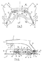
- la figure 3 est une vue de dessus d'un berceau avant selon un second mode de réalisation sans la paroi supérieure constituant celui-ci ; et
- la figure 4 est une vue en coupe suivant la ligne IV - IV de la figure 3, du berceau monté sur la caisse d'un véhicule.
- Figure 1 is a top view of a cradle before organ support of a motor vehicle according to the invention;
- Figure 2 is a sectional view along line II - II of Figure 1, mounted on the body of a vehicle;
- Figure 2a is a section along line III - III of Figure 1 of an alternative attachment;
- Figure 3 is a top view of a front cradle according to a second embodiment without the upper wall constituting it; and
- Figure 4 is a sectional view along line IV - IV of Figure 3, of the cradle mounted on the body of a vehicle.
En se rapportant aux figures 1 et 2, on a représenté un berceau
avant 1 équipé de diverses pièces de liaison au sol du train avant d'un
véhicule automobile et relié à une caisse 2 de ce véhicule de façon
connue par des moyens de fixation 3 du type boulons traversant le
berceau 1 par des orifices 4 prévus dans ce dernier.Referring to Figures 1 and 2, there is shown a
Le berceau 1 est constitué de deux parties ; d'une part d'une
traverse supérieure 1a, de forme générale en U, pourvue d'une paroi
supérieure 9 et de parois latérales 9b, et d'autre part d'une semelle 1b de
profil sensiblement plan et parallèle au sol, qui sont assemblées l'une à
l'autre par un cordon de soudure en périphérie non représenté.The
On notera que les points de fixation du berceau sur la caisse 2 sont
répartis, classiquement de part et d'autre d'un plan vertical P représentant
le plan médian du véhicule, notamment par deux fixations 5 à l'avant qui
sont liées aux brancards 6 avant de caisse, comme visible à la figure 2, et
par deux fixations 7 à l'arrière liées au plancher 8 d'un habitacle du
véhicule et constituées d'une entretoise 7a disposée verticalement entre
la paroi 9 et la semelle 1b.Note that the attachment points of the cradle on the
Le berceau 1 ainsi réalisé présente comme visible sur la figure 2,
une section transversale sensiblement rectangulaire et creuse.The
La traverse 1a est pourvue d'une paroi supérieure 9 sur laquelle
repose un boítier de direction, non représentée, recevant une crémaillère
transversale au véhicule et fixée par deux vis traversant le berceau par
des entretoises tubulaires 10a, 10b serrées entre la semelle 1b et la
paroi 9.The
La semelle 1b comporte, comme visible à la figure 2, un logement 11
apte à recevoir l'un des deux paliers 12 d'une barre anti-devers 13.
Chacun des paliers 12 est maintenu par une bride de fixation 14 fixée par
des moyens connus de fixation du type visserie.The sole 1b comprises, as visible in FIG. 2, a
Le berceau 1 comporte également dans ses parois latérales 9b
parallèles au plan médian P du véhicule des ouvertures classiques, non
représentées, pour permettre le passage des extrémités d'un triangle de
suspension inférieur qui est lié au berceau, par des articulations fixées
entre la traverse supérieure et la semelle, par deux vis traversant le
berceau respectivement par une entretoise tubulaire, non représentée,
interposée entre la paroi 9 et la semelle 1b, au droit de trous 15 pratiqués
dans celle-ci.The
Selon la présente invention, le berceau 1 est pourvu entre la paroi 9
et la semelle 1b d'un moyen de renfort 16 afin d'augmenter sa résistance
à l'écrasement en direction longitudinale lors d'un choc frontal du
véhicule.According to the present invention, the
Ce moyen de renfort est constitué d'une barre 16, de préférence
tubulaire, à partie centrale transversalement au véhicule disposé juste
devant des entretoises 10a, 10b de fixation d'un boítier de direction et qui
est cintré en forme de C, de part et d'autre de ces entretoises, vers
l'arrière en formant deux branches 17 qui sont inclinées et dirigées le plus
droit possible vers les entretoises 7a de fixation arrière du berceau 1 sur
la caisse 2 du véhicule. This reinforcing means consists of a
L'extrémité 17a de chacune des branches 17 est légèrement aplatie
et est pourvue d'un évidement 18 apte à enfourcher partiellement
l'entretoise de fixation 7a et est fixée à cette dernière par soudure. La
barre est maintenue en hauteur au moyen d'au moins deux pattes 19
disposées de part et d'autre du plan médian P, chacune de ces pattes 19
étant soudée d'une part sur la barre -ou tube- 16 et d'autre part sur le
berceau 1, comme visible à la figure 2. La barre 16 s'étend sensiblement
dans le prolongement avant longitudinal du plancher, c'est-à-dire au
voisinage d'un plan horizontal Q sensiblement confondu avec le plancher
avant 8, de manière à permettre le meilleur passage des efforts
longitudinaux par le plancher 8 qui est positionné en bas de caisse 2 et
qui présente une résistance importante à l'écrasement.The
Ainsi, avantageusement, en cas de collision frontale, le passage des
efforts s'effectue sensiblement dans un même plan Q, évitant le risque de
créer des couples d'efforts résistants qui pourraient déformer le tablier 20
du véhicule et faire reculer dans l'habitacle un pédalier habituellement
fixé au tablier.Thus, advantageously, in the event of a frontal collision, the passage of
efforts are made substantially in the same Q plane, avoiding the risk of
create pairs of resistant forces which could deform the
Dans une variante de fixation de la barre 16 en hauteur, représentée
à la figure 2a, la traverse la comporte sur la paroi supérieure 9 au moins
une déformation 21 locale prenant la forme extérieure du tube 16 de telle
sorte que ce dernier soit positionné à l'intérieur lors du montage et fixé à
celle-ci par des cordons de soudure 22. La semelle 1b est également
pourvue d'une déformation 23 de manière à former une proéminence 24
vers l'intérieur du berceau permettant de maintenir le tube 16 à une
hauteur définie. Une soudure 25, dite « soudure bouchon », maintient le
tube 16 sur la semelle 1b après assemblage de celle-ci avec la paroi 9.
Ces déformations 21 et 23 réalisées en vis-à-vis permettent de coiffer,
lors de l'assemblage de la paroi 9 et de la semelle, le tube 16 et de
l'immobiliser dans une position en hauteur adéquate.In a variant for fixing the
On a représenté aux figures 3 et 4, un second mode de réalisation de l'invention, les éléments identiques aux figures 1 et 2 comportent, dans un souci de simplification de la description, les mêmes références. There is shown in Figures 3 and 4, a second embodiment of the invention, the elements identical to Figures 1 and 2 include, in for the sake of simplification of the description, the same references.
Le moyen de renfort 16 est constitué d'un tube 26 pourvu d'une
partie centrale transversalement au véhicule disposé juste devant des
entretoises 10a, 10b de fixation d'un boítier de direction et qui est cintré
au droit de ces entretoises 10a, 10b vers l'arrière du véhicule délimitant
ainsi deux branches 27.The reinforcing means 16 consists of a
Chacune des branches 27 est prolongée jusqu'aux entretoises 7a de
fixation arrière du berceau 1 par un barreau cylindrique 28.Each of the
L'extrémité avant de ce barreau 28 est emmanché et soudé dans la
partie terminale arrière associée du tube 26, et l'autre extrémité est
soudée à l'une des entretoises 7a de fixation arrière du berceau. Le
barreau est légèrement cintré vers le haut, dans un plan vertical, au droit
du palier 12 de la barre anti-dévers 13, comme visible à la figure 4, afin
de permettre le passage de cette dernière.The front end of this
Le tube 26 est pourvu au niveau de chaque cintrage d'un gousset 29
de renfort maintenu par un cordon de soudure 30. Chacun des goussets
29 est fixé par soudure 31 à l'entretoise 10a,10b qui lui correspond
comme visible sur les figures 3 et 4.The
Un tel moyen de renfort présente l'avantage de pouvoir être dimensionné suivant la masse du véhicule en intervenant sur le diamètre extérieur, l'épaisseur, la forme et la matière du tube creux, plein ou partiellement plein, de combiner également les différents matériaux afin de définir un berceau qui satisfasse parfaitement les réglementations et les normes de sécurité passive en cas de choc frontal.Such a reinforcement means has the advantage of being able to be dimensioned according to the mass of the vehicle by adjusting the diameter outside, thickness, shape and material of the hollow tube, solid or partially full, also to combine the different materials so to define a cradle that perfectly meets the regulations and passive safety standards in the event of a frontal impact.
On comprend aisément à la lecture de la description ci-dessus qu'un berceau ainsi conçu permet de répondre de manière satisfaisante aux critères mécaniques nécessaires en cas de choc frontal sans entraíner un coût excessif, par des moyens simples qui n'engendrent pas une augmentation de la masse importante.It is easy to understand from reading the description above that cradle thus designed makes it possible to respond satisfactorily to mechanical criteria necessary in the event of a frontal impact without causing excessive cost, by simple means which do not generate significant increase in mass.
Claims (9)
caractérisé en ce qu'il comporte un moyen de renfort (16; 26) formant une barre, disposée entre la paroi supérieure (9) et la semelle (1b) sensiblement au niveau du plancher (8).Front cradle (1) of a motor vehicle, on which ground connection members are fixed, consisting of a cross member (1a) provided with an upper wall (9) and a sole (1b), and connected to the body (2) of the vehicle, in particular at the front with two side stretchers (6) and at the rear at the floor (8) of a vehicle interior by fastening elements arranged on either side of the vertical plane median (P) of the vehicle,
characterized in that it comprises a reinforcement means (16; 26) forming a bar, arranged between the upper wall (9) and the sole (1b) substantially at the level of the floor (8).
caractérisé en ce que le moyen de renfort (16; 26) est une barre au moins en majeure partie tubulaire.Cradle according to claim 1,
characterized in that the reinforcing means (16; 26) is an at least mainly tubular bar.
caractérisé en ce que le moyen de renfort (16; 26) comporte à l'avant une partie centrale transversale au véhicule, reliée par deux cintrages opposés respectivement à deux parties latérales inclinées vers l'arrière formant deux branches (17; 27) aboutissant chacune à une entretoise (7a) de fixation arrière du berceau (1).Cradle according to one of claims 1 to 2,
characterized in that the reinforcing means (16; 26) comprises at the front a central part transverse to the vehicle, connected by two bends opposite respectively to two lateral parts inclined towards the rear forming two branches (17; 27) each leading to a spacer (7a) for rear fixing of the cradle (1).
caractérisé en ce que les deux cintrages sont disposés respectivement devant et contre deux entretoises verticales (10a, 10b) serrées entre la semelle (1b) et la paroi supérieure (9).Cradle according to claim 3,
characterized in that the two bends are disposed respectively in front of and against two vertical spacers (10a, 10b) clamped between the sole (1b) and the upper wall (9).
caractérisé en ce que ces entretoises (10a, 10b) sont tubulaires et traversées axialement chacune par une vis de fixation d'un boítier de direction.Cradle according to claim 4,
characterized in that these spacers (10a, 10b) are tubular and axially traversed each by a fixing screw of a steering box.
caractérisé en ce que la barre (26) est pourvu au droit de chaque cintrage d'un gousset de renfort (29) rendu solidaire de l'une des entretoises (10a, 10b) de fixation d'un boítier de direction.Cradle according to one of claims 3 to 5,
characterized in that the bar (26) is provided at the right of each bending with a reinforcing gusset (29) made integral with one of the spacers (10a, 10b) for fixing a steering box.
caractérisé en ce que chacune des branches (27) comporte une partie arrière constituée par un barreau cylindrique (28) et une partie avant tubulaire recevant l'extrémité avant du barreau.Cradle according to one of claims 3 to 6,
characterized in that each of the branches (27) has a rear part constituted by a cylindrical bar (28) and a tubular front part receiving the front end of the bar.
caractérisé en ce que le moyen de renfort (16) est maintenu en hauteur par l'intermédiaire d'au moins deux pattes (19) disposées de part et d'autre du plan médian (P), chacune de ces pattes (19) étant soudée d'une part sur le moyen de renfort (16) et d'autre part sur le berceau (1).Cradle according to one of the preceding claims,
characterized in that the reinforcing means (16) is maintained in height by means of at least two legs (19) arranged on either side of the median plane (P), each of these legs (19) being welded on the one hand to the reinforcement means (16) and on the other hand to the cradle (1).
caractérisé en ce que la paroi supérieure (9) et la semelle (1b) sont pourvues de déformations locales (21, 23) respectives disposées en vis-à-vis et prenant la forme extérieure de la barre (16) de manière à maintenir celle-ci à une hauteur définie.Cradle according to one of the preceding claims,
characterized in that the upper wall (9) and the sole (1b) are provided with respective local deformations (21, 23) arranged opposite and taking the external shape of the bar (16) so as to maintain that -this at a defined height.
Applications Claiming Priority (2)
| Application Number | Priority Date | Filing Date | Title |
|---|---|---|---|
| FR9709101A FR2766150B1 (en) | 1997-07-18 | 1997-07-18 | FRONT CRADLE OF MOTOR VEHICLE |
| FR9709101 | 1997-07-18 |
Publications (2)
| Publication Number | Publication Date |
|---|---|
| EP0891916A1 true EP0891916A1 (en) | 1999-01-20 |
| EP0891916B1 EP0891916B1 (en) | 2001-10-10 |
Family
ID=9509335
Family Applications (1)
| Application Number | Title | Priority Date | Filing Date |
|---|---|---|---|
| EP19980401786 Expired - Lifetime EP0891916B1 (en) | 1997-07-18 | 1998-07-16 | Front sub-frame for a motor vehicle |
Country Status (4)
| Country | Link |
|---|---|
| EP (1) | EP0891916B1 (en) |
| DE (1) | DE69801962T2 (en) |
| ES (1) | ES2165664T3 (en) |
| FR (1) | FR2766150B1 (en) |
Cited By (2)
| Publication number | Priority date | Publication date | Assignee | Title |
|---|---|---|---|---|
| EP2388182A1 (en) * | 2007-10-17 | 2011-11-23 | Honda Motor Co., Ltd. | Front vehicle body structure |
| FR3060509A1 (en) * | 2016-12-16 | 2018-06-22 | Renault S.A.S | STRUCTURAL ASSEMBLY UNDER AUTOMOTIVE CHASSIS. |
Families Citing this family (1)
| Publication number | Priority date | Publication date | Assignee | Title |
|---|---|---|---|---|
| DE10352078A1 (en) * | 2003-11-07 | 2005-06-09 | Volkswagen Ag | Supporting frame for motor vehicle, has cross bar module, two side rail modules, and two console modules that are welded together to form U-shaped arrangement and set with respect to their optimal loading in frame |
Citations (2)
| Publication number | Priority date | Publication date | Assignee | Title |
|---|---|---|---|---|
| DE2627902A1 (en) * | 1976-06-22 | 1978-01-05 | Daimler Benz Ag | Box structure for supporting vehicle steering gear - has internal tube connecting opposite walls of box and welded in position |
| GB2207100A (en) * | 1987-07-17 | 1989-01-25 | Nissan Motor | Center member structure for motor vehicle |
-
1997
- 1997-07-18 FR FR9709101A patent/FR2766150B1/en not_active Expired - Fee Related
-
1998
- 1998-07-16 ES ES98401786T patent/ES2165664T3/en not_active Expired - Lifetime
- 1998-07-16 DE DE1998601962 patent/DE69801962T2/en not_active Expired - Lifetime
- 1998-07-16 EP EP19980401786 patent/EP0891916B1/en not_active Expired - Lifetime
Patent Citations (2)
| Publication number | Priority date | Publication date | Assignee | Title |
|---|---|---|---|---|
| DE2627902A1 (en) * | 1976-06-22 | 1978-01-05 | Daimler Benz Ag | Box structure for supporting vehicle steering gear - has internal tube connecting opposite walls of box and welded in position |
| GB2207100A (en) * | 1987-07-17 | 1989-01-25 | Nissan Motor | Center member structure for motor vehicle |
Cited By (2)
| Publication number | Priority date | Publication date | Assignee | Title |
|---|---|---|---|---|
| EP2388182A1 (en) * | 2007-10-17 | 2011-11-23 | Honda Motor Co., Ltd. | Front vehicle body structure |
| FR3060509A1 (en) * | 2016-12-16 | 2018-06-22 | Renault S.A.S | STRUCTURAL ASSEMBLY UNDER AUTOMOTIVE CHASSIS. |
Also Published As
| Publication number | Publication date |
|---|---|
| EP0891916B1 (en) | 2001-10-10 |
| DE69801962D1 (en) | 2001-11-15 |
| DE69801962T2 (en) | 2002-05-29 |
| FR2766150A1 (en) | 1999-01-22 |
| ES2165664T3 (en) | 2002-03-16 |
| FR2766150B1 (en) | 1999-08-27 |
Similar Documents
| Publication | Publication Date | Title |
|---|---|---|
| FR2710893A1 (en) | Chassis for a vehicle, especially for a motor vehicle. | |
| FR2503653A1 (en) | AUTOMOTIVE BODYWORK STRUCTURE | |
| FR2772317A1 (en) | Vehicle seat with height adjustment mechanism | |
| FR2613989A1 (en) | SAFETY ARCEAU FOR MOTOR VEHICLE | |
| EP0891916B1 (en) | Front sub-frame for a motor vehicle | |
| FR2507131A1 (en) | RIGID AXLE SUSPENSION FOR MOTOR VEHICLE | |
| FR2884761A1 (en) | Motor vehicle powered axle, has cross piece including two ends fixed on support structures, where rear ends of each of longitudinal arms are mounted on corresponding support structure of cross piece by using spacing parts | |
| FR2491856A1 (en) | CARRIER STRUCTURE FOR A MOTOR VEHICLE BODY, PARTICULARLY FOR A PRIVATE CAR | |
| FR2618733A1 (en) | Load-bearing axle for motor vehicle | |
| FR2755908A1 (en) | ONE-PIECE FIXING CONSOLE FOR AN OSCILLATION SHOCK ABSORBER | |
| EP2199120A1 (en) | Rear wheel suspension system comprising two suspension arms having vertical opening | |
| EP0683088B1 (en) | Front wheel suspension assembly with double transversal triangles and motor vehicle equipped with such an assembly | |
| EP0659631B1 (en) | Front structure of a motor car and motor car equipped with this structure | |
| FR2753931A1 (en) | Vehicle wheel triangular suspension | |
| FR2825340A1 (en) | Controlled rigidity swinging arm for off road motor cycle has curved sections in fork legs to allow controlled vertical deflection of legs under load | |
| FR2864471A1 (en) | Wheel shaft for use in vehicle, has crosspiece connecting two longitudinal arms, where each arm has side rail whose front portion has bent portion extending about specific angle | |
| EP1078782B1 (en) | Suspension device for the front wheel of a motor car | |
| FR2959449A1 (en) | Semi-rigid type assembled rear axle for supporting rear wheel of motor vehicle, has cross-piece whose end is connected to suspension arm, and spring whose retainer and support constitute integrated assembly before assembling rear axle | |
| EP1184260A1 (en) | Body structure with lower beams fixed by boxes | |
| EP0743237B1 (en) | Fore-axle assembly on vehicle body | |
| FR2895356A1 (en) | Motor vehicle rear floor section is connected to front floor section by step formed by rising front floor panel and transverse hollow beam of sheet metal | |
| FR3121117A1 (en) | Motor vehicle with reinforced rear structure | |
| FR2977222A3 (en) | Chassis for car, has reinforcement defining spacer and fixed at shock absorber that is placed in vicinity of crosspiece and rear skirt, where reinforcement extending in hollow body is defined in rear skirt unit | |
| EP1026069B1 (en) | Protection device against a frontal impact attached to a front part of a car | |
| FR3067318A1 (en) | MOTOR VEHICLE CRADLE WITH INTEGRATED CONTRA-IMPACTOR |
Legal Events
| Date | Code | Title | Description |
|---|---|---|---|
| PUAI | Public reference made under article 153(3) epc to a published international application that has entered the european phase |
Free format text: ORIGINAL CODE: 0009012 |
|
| AK | Designated contracting states |
Kind code of ref document: A1 Designated state(s): CH DE ES GB IT LI PT SE |
|
| AX | Request for extension of the european patent |
Free format text: AL;LT;LV;MK;RO;SI |
|
| 17P | Request for examination filed |
Effective date: 19990219 |
|
| AKX | Designation fees paid |
Free format text: CH DE ES GB IT LI PT SE |
|
| 17Q | First examination report despatched |
Effective date: 20000929 |
|
| GRAG | Despatch of communication of intention to grant |
Free format text: ORIGINAL CODE: EPIDOS AGRA |
|
| GRAG | Despatch of communication of intention to grant |
Free format text: ORIGINAL CODE: EPIDOS AGRA |
|
| GRAH | Despatch of communication of intention to grant a patent |
Free format text: ORIGINAL CODE: EPIDOS IGRA |
|
| GRAH | Despatch of communication of intention to grant a patent |
Free format text: ORIGINAL CODE: EPIDOS IGRA |
|
| GRAA | (expected) grant |
Free format text: ORIGINAL CODE: 0009210 |
|
| AK | Designated contracting states |
Kind code of ref document: B1 Designated state(s): CH DE ES GB IT LI PT SE |
|
| REG | Reference to a national code |
Ref country code: CH Ref legal event code: EP |
|
| REF | Corresponds to: |
Ref document number: 69801962 Country of ref document: DE Date of ref document: 20011115 |
|
| REG | Reference to a national code |
Ref country code: GB Ref legal event code: IF02 |
|
| PG25 | Lapsed in a contracting state [announced via postgrant information from national office to epo] |
Ref country code: SE Free format text: LAPSE BECAUSE OF FAILURE TO SUBMIT A TRANSLATION OF THE DESCRIPTION OR TO PAY THE FEE WITHIN THE PRESCRIBED TIME-LIMIT Effective date: 20020110 Ref country code: PT Free format text: LAPSE BECAUSE OF FAILURE TO SUBMIT A TRANSLATION OF THE DESCRIPTION OR TO PAY THE FEE WITHIN THE PRESCRIBED TIME-LIMIT Effective date: 20020110 |
|
| GBT | Gb: translation of ep patent filed (gb section 77(6)(a)/1977) |
Effective date: 20011220 |
|
| REG | Reference to a national code |
Ref country code: ES Ref legal event code: FG2A Ref document number: 2165664 Country of ref document: ES Kind code of ref document: T3 |
|
| PG25 | Lapsed in a contracting state [announced via postgrant information from national office to epo] |
Ref country code: LI Free format text: LAPSE BECAUSE OF NON-PAYMENT OF DUE FEES Effective date: 20020731 Ref country code: CH Free format text: LAPSE BECAUSE OF NON-PAYMENT OF DUE FEES Effective date: 20020731 |
|
| PLBE | No opposition filed within time limit |
Free format text: ORIGINAL CODE: 0009261 |
|
| STAA | Information on the status of an ep patent application or granted ep patent |
Free format text: STATUS: NO OPPOSITION FILED WITHIN TIME LIMIT |
|
| 26N | No opposition filed | ||
| REG | Reference to a national code |
Ref country code: CH Ref legal event code: PL |
|
| REG | Reference to a national code |
Ref country code: GB Ref legal event code: 746 Effective date: 20070118 |
|
| REG | Reference to a national code |
Ref country code: ES Ref legal event code: GC2A Effective date: 20110316 |
|
| PGFP | Annual fee paid to national office [announced via postgrant information from national office to epo] |
Ref country code: IT Payment date: 20110625 Year of fee payment: 14 |
|
| PGFP | Annual fee paid to national office [announced via postgrant information from national office to epo] |
Ref country code: GB Payment date: 20110701 Year of fee payment: 14 Ref country code: ES Payment date: 20110623 Year of fee payment: 14 |
|
| GBPC | Gb: european patent ceased through non-payment of renewal fee |
Effective date: 20120716 |
|
| PG25 | Lapsed in a contracting state [announced via postgrant information from national office to epo] |
Ref country code: GB Free format text: LAPSE BECAUSE OF NON-PAYMENT OF DUE FEES Effective date: 20120716 |
|
| PG25 | Lapsed in a contracting state [announced via postgrant information from national office to epo] |
Ref country code: IT Free format text: LAPSE BECAUSE OF NON-PAYMENT OF DUE FEES Effective date: 20120716 |
|
| REG | Reference to a national code |
Ref country code: ES Ref legal event code: FD2A Effective date: 20131021 |
|
| PG25 | Lapsed in a contracting state [announced via postgrant information from national office to epo] |
Ref country code: ES Free format text: LAPSE BECAUSE OF NON-PAYMENT OF DUE FEES Effective date: 20120717 |
|
| PGFP | Annual fee paid to national office [announced via postgrant information from national office to epo] |
Ref country code: DE Payment date: 20140620 Year of fee payment: 17 |
|
| REG | Reference to a national code |
Ref country code: DE Ref legal event code: R119 Ref document number: 69801962 Country of ref document: DE |
|
| PG25 | Lapsed in a contracting state [announced via postgrant information from national office to epo] |
Ref country code: DE Free format text: LAPSE BECAUSE OF NON-PAYMENT OF DUE FEES Effective date: 20160202 |