EP0891467B1 - Foret au diamant polycristallin presentant une meilleure durabilite et resistance a l'usure - Google Patents
Foret au diamant polycristallin presentant une meilleure durabilite et resistance a l'usure Download PDFInfo
- Publication number
- EP0891467B1 EP0891467B1 EP97905951A EP97905951A EP0891467B1 EP 0891467 B1 EP0891467 B1 EP 0891467B1 EP 97905951 A EP97905951 A EP 97905951A EP 97905951 A EP97905951 A EP 97905951A EP 0891467 B1 EP0891467 B1 EP 0891467B1
- Authority
- EP
- European Patent Office
- Prior art keywords
- cutting
- cutter
- cutting element
- substrate
- longitudinal axis
- Prior art date
- Legal status (The legal status is an assumption and is not a legal conclusion. Google has not performed a legal analysis and makes no representation as to the accuracy of the status listed.)
- Expired - Lifetime
Links
- 229910003460 diamond Inorganic materials 0.000 title description 184
- 239000010432 diamond Substances 0.000 title description 184
- 238000005520 cutting process Methods 0.000 claims description 234
- 239000000758 substrate Substances 0.000 claims description 105
- 239000000463 material Substances 0.000 claims description 51
- 230000015572 biosynthetic process Effects 0.000 claims description 50
- 238000005755 formation reaction Methods 0.000 claims description 50
- 238000005553 drilling Methods 0.000 claims description 17
- 238000005096 rolling process Methods 0.000 claims description 12
- 230000001154 acute effect Effects 0.000 claims description 5
- 238000005065 mining Methods 0.000 claims description 3
- 239000003381 stabilizer Substances 0.000 claims description 3
- 239000011435 rock Substances 0.000 description 34
- UONOETXJSWQNOL-UHFFFAOYSA-N tungsten carbide Chemical compound [W+]#[C-] UONOETXJSWQNOL-UHFFFAOYSA-N 0.000 description 12
- 230000008901 benefit Effects 0.000 description 11
- 238000005452 bending Methods 0.000 description 9
- 238000004519 manufacturing process Methods 0.000 description 9
- 238000004901 spalling Methods 0.000 description 8
- 230000009471 action Effects 0.000 description 7
- 229910052751 metal Inorganic materials 0.000 description 6
- 239000002184 metal Substances 0.000 description 6
- 230000002093 peripheral effect Effects 0.000 description 6
- 239000011230 binding agent Substances 0.000 description 5
- 238000013461 design Methods 0.000 description 5
- 230000000694 effects Effects 0.000 description 5
- 230000003628 erosive effect Effects 0.000 description 5
- 239000002245 particle Substances 0.000 description 5
- 230000007423 decrease Effects 0.000 description 4
- 230000035515 penetration Effects 0.000 description 4
- 238000009527 percussion Methods 0.000 description 4
- 238000012360 testing method Methods 0.000 description 4
- 239000010936 titanium Substances 0.000 description 4
- 229910052721 tungsten Inorganic materials 0.000 description 4
- 238000005299 abrasion Methods 0.000 description 3
- 230000003247 decreasing effect Effects 0.000 description 3
- 239000010955 niobium Substances 0.000 description 3
- 238000010008 shearing Methods 0.000 description 3
- 238000005245 sintering Methods 0.000 description 3
- 235000019738 Limestone Nutrition 0.000 description 2
- 230000009286 beneficial effect Effects 0.000 description 2
- 238000005219 brazing Methods 0.000 description 2
- 238000010276 construction Methods 0.000 description 2
- 238000001816 cooling Methods 0.000 description 2
- 238000005336 cracking Methods 0.000 description 2
- 239000013078 crystal Substances 0.000 description 2
- 238000009826 distribution Methods 0.000 description 2
- 239000012530 fluid Substances 0.000 description 2
- 238000000227 grinding Methods 0.000 description 2
- 229910052735 hafnium Inorganic materials 0.000 description 2
- 230000006872 improvement Effects 0.000 description 2
- 238000000034 method Methods 0.000 description 2
- 238000012986 modification Methods 0.000 description 2
- 230000004048 modification Effects 0.000 description 2
- 229910052758 niobium Inorganic materials 0.000 description 2
- 230000008569 process Effects 0.000 description 2
- 229910052715 tantalum Inorganic materials 0.000 description 2
- 229910052719 titanium Inorganic materials 0.000 description 2
- 238000012546 transfer Methods 0.000 description 2
- WFKWXMTUELFFGS-UHFFFAOYSA-N tungsten Chemical compound [W] WFKWXMTUELFFGS-UHFFFAOYSA-N 0.000 description 2
- 239000010937 tungsten Substances 0.000 description 2
- 229910052582 BN Inorganic materials 0.000 description 1
- PZNSFCLAULLKQX-UHFFFAOYSA-N Boron nitride Chemical compound N#B PZNSFCLAULLKQX-UHFFFAOYSA-N 0.000 description 1
- RYGMFSIKBFXOCR-UHFFFAOYSA-N Copper Chemical compound [Cu] RYGMFSIKBFXOCR-UHFFFAOYSA-N 0.000 description 1
- RTAQQCXQSZGOHL-UHFFFAOYSA-N Titanium Chemical compound [Ti] RTAQQCXQSZGOHL-UHFFFAOYSA-N 0.000 description 1
- 238000013459 approach Methods 0.000 description 1
- 230000003190 augmentative effect Effects 0.000 description 1
- 239000003054 catalyst Substances 0.000 description 1
- 239000010941 cobalt Substances 0.000 description 1
- 229910017052 cobalt Inorganic materials 0.000 description 1
- GUTLYIVDDKVIGB-UHFFFAOYSA-N cobalt atom Chemical compound [Co] GUTLYIVDDKVIGB-UHFFFAOYSA-N 0.000 description 1
- 230000006835 compression Effects 0.000 description 1
- 238000007906 compression Methods 0.000 description 1
- 229910052802 copper Inorganic materials 0.000 description 1
- 239000010949 copper Substances 0.000 description 1
- 230000007812 deficiency Effects 0.000 description 1
- 230000000593 degrading effect Effects 0.000 description 1
- 230000032798 delamination Effects 0.000 description 1
- 230000002939 deleterious effect Effects 0.000 description 1
- 230000001419 dependent effect Effects 0.000 description 1
- 230000001627 detrimental effect Effects 0.000 description 1
- 230000003028 elevating effect Effects 0.000 description 1
- 230000002708 enhancing effect Effects 0.000 description 1
- 230000008570 general process Effects 0.000 description 1
- 239000010438 granite Substances 0.000 description 1
- VBJZVLUMGGDVMO-UHFFFAOYSA-N hafnium atom Chemical compound [Hf] VBJZVLUMGGDVMO-UHFFFAOYSA-N 0.000 description 1
- 230000020169 heat generation Effects 0.000 description 1
- 238000002386 leaching Methods 0.000 description 1
- 239000006028 limestone Substances 0.000 description 1
- 239000007788 liquid Substances 0.000 description 1
- 239000007791 liquid phase Substances 0.000 description 1
- 230000005923 long-lasting effect Effects 0.000 description 1
- 230000007774 longterm Effects 0.000 description 1
- 238000003754 machining Methods 0.000 description 1
- 238000005259 measurement Methods 0.000 description 1
- 150000001247 metal acetylides Chemical class 0.000 description 1
- GUCVJGMIXFAOAE-UHFFFAOYSA-N niobium atom Chemical compound [Nb] GUCVJGMIXFAOAE-UHFFFAOYSA-N 0.000 description 1
- 239000003921 oil Substances 0.000 description 1
- 239000011148 porous material Substances 0.000 description 1
- 230000002028 premature Effects 0.000 description 1
- 238000003825 pressing Methods 0.000 description 1
- 230000002265 prevention Effects 0.000 description 1
- 230000001737 promoting effect Effects 0.000 description 1
- 230000004044 response Effects 0.000 description 1
- VSZWPYCFIRKVQL-UHFFFAOYSA-N selanylidenegallium;selenium Chemical compound [Se].[Se]=[Ga].[Se]=[Ga] VSZWPYCFIRKVQL-UHFFFAOYSA-N 0.000 description 1
- 229910052710 silicon Inorganic materials 0.000 description 1
- 239000010703 silicon Substances 0.000 description 1
- GUVRBAGPIYLISA-UHFFFAOYSA-N tantalum atom Chemical compound [Ta] GUVRBAGPIYLISA-UHFFFAOYSA-N 0.000 description 1
- 229910052720 vanadium Inorganic materials 0.000 description 1
- LEONUFNNVUYDNQ-UHFFFAOYSA-N vanadium atom Chemical compound [V] LEONUFNNVUYDNQ-UHFFFAOYSA-N 0.000 description 1
- 229910052726 zirconium Inorganic materials 0.000 description 1
Images


Classifications
-
- E—FIXED CONSTRUCTIONS
- E21—EARTH DRILLING; MINING
- E21B—EARTH DRILLING, e.g. DEEP DRILLING; OBTAINING OIL, GAS, WATER, SOLUBLE OR MELTABLE MATERIALS OR A SLURRY OF MINERALS FROM WELLS
- E21B10/00—Drill bits
- E21B10/46—Drill bits characterised by wear resisting parts, e.g. diamond inserts
- E21B10/56—Button-type inserts
- E21B10/567—Button-type inserts with preformed cutting elements mounted on a distinct support, e.g. polycrystalline inserts
- E21B10/5673—Button-type inserts with preformed cutting elements mounted on a distinct support, e.g. polycrystalline inserts having a non planar or non circular cutting face
Definitions
- This invention relates to devices used in drilling and boring through subterranean formations. More particularly, this invention relates to a polycrystalline diamond or other superabrasive cutter intended to be installed on a drill bit or other tool used for earth or rock boring, such as may occur in the drilling or enlarging of an oil, gas, geothermal or other subterranean borehole, and to bits and tools so equipped.
- bits which are generally used to drill through subterranean formations. These bit types are: (a) percussion bits (also called impact bits); (b) rolling cone bits, including tri-cone bits; and (c) drag bits or fixed cutter rotary bits (including core bits so configured), the majority of which currently employ diamond or other superabrasive cutters, polycrystalline diamond compact (PDC) cutters being most prevalent.
- percussion bits also called impact bits
- rolling cone bits including tri-cone bits
- drag bits or fixed cutter rotary bits including core bits so configured
- tools which are employed to cut or enlarge a borehole or which may employ superabrasive cutters, inserts or plugs on the surface thereof as cutters or wear-prevention elements.
- tools might include, merely by way of example, reamers, stabilizers, tool joints, wear knots and steering tools.
- formation cutting tools employed in subterranean mining such as drills and boring tools.
- Percussion bits are used with boring apparatus known in the art that moves through a geologic formation by a series of successive impacts against the formation, causing a breaking and loosening of the material of the formation. It is expected that the cutter of the invention will have use in the field of percussion bits.
- Bits referred to in the art as rock bits, tri-cone bits or rolling cone bits are used to bore through a variety of geologic formations, and demonstrate high efficiency in firmer rock types.
- Prior art rolling cone bits tend to be somewhat less expensive than PDC drag bits, with limited performance in comparison. However, they have good durability in many hard-to-drill formations.
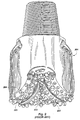
- An exemplary prior art rolling cone bit is shown in FIG. 2.
- a typical rolling cone bit operates by the use of three rotatable cones oriented substantially transversely to the bit axis in a triangular arrangement, with the narrow cone ends facing a point in the center of the triangle which they form. The cones have cutters formed or placed on their surfaces.
- Prior art rolling cone bits may achieve a rate of penetration (ROP) through a hard rock formation ranging from less than .3 meter (one foot) per hour up to about 9 meters (thirty feet) per hour. It is expected that the cutter of the invention will have use in the field of rolling cone bits as a cone insert for a rolling cone, as a gage cutter or trimmer, and on wear pads on the gage.
- ROP rate of penetration
- a third type of bit used in the prior art is a drag bit or fixed-cutter bit.
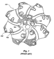
- An exemplary drag bit is shown in FIG. 1.
- the drag bit of FIG. 1 is designed to be turned in a clockwise direction (looking downward at a bit being used in a hole, or counterclockwise if looking at the bit from its cutting end as shown in FIG. 1) about its longitudinal axis.
- the majority of current drag bit designs employ diamond cutters comprising polycrystalline diamond compacts (PDCs) mounted to a substrate, typically of cemented tungsten carbide (WC).
- State-of the-art drag bits may achieve an ROP ranging from about .3 meter (one foot) to in excess of three hundred five meters (one thousand feet) per hour.
- a disadvantage of state-of the-art PDC drag bits is that they may prematurely wear due to impact failure of the PDC cutters, as such cutters may be damaged very quickly if used in highly stressed or tougher formations composed of limestones, dolomites, anhydrites, cemented sandstones interbedded formations such as shale with sequences of sandstone, limestone and dolomites, or formations containing hard "stringers.” It is expected that the cutter of the invention will have use in the field of drag bits as a cutter, as a gage cutter or trimmer, and on wear pads on the gage.
- a PDC cutter typically has a diamond layer or table formed under high temperature and pressure conditions to a cemented carbide substrate (such as cemented tungsten carbide) containing a metal binder or catalyst such as cobalt.
- the substrate may be brazed or otherwise joined to an attachment member such as a stud or to a cylindrical backing element to enhance its affixation to the bit face.
- the cutting element may be mounted to a drill bit either by press-fitting or otherwise locking the stud into a receptacle on a steel-body drag bit, or by brazing the cutter substrate (with or without cylindrical backing) directly into a preformed pocket, socket or other receptacle on the face of a bit body, as on a matrix-type bit formed of WC particles cast in a solidified, usually copper-based, binder as known in the art.
- a PDC is normally fabricated by placing a disk-shaped cemented carbide substrate into a container or cartridge with a layer of diamond crystals or grains loaded into the cartridge adjacent one face of the substrate.
- a number of such cartridges are typically loaded into an ultra-high pressure press.
- the substrates and adjacent diamond crystal layers are then compressed under ultra-high temperature and pressure conditions.
- the ultra-high pressure and temperature conditions cause the metal binder from the substrate body to become liquid and sweep from the region behind the substrate face next to the diamond layer through the diamond grains and act as a reactive liquid phase to promote a sintering of the diamond grains to form the polycrystalline diamond structure.
- the diamond grains become mutually bonded to form a diamond table over the substrate face, which diamond table is also bonded to the substrate face.
- the metal binder may remain in the diamond layer within the pores existing between the diamond grains or may be removed and optionally replaced by another material, as known in the art, to form a so-called thermally stable diamond ("TSD").
- TSD thermally stable diamond
- the binder is removed by leaching or the diamond table is formed with silicon, a material having a coefficient of thermal expansion (CTE) similar to that of diamond.
- CTE coefficient of thermal expansion
- Prior art PDCs experience durability problems in high load applications. They have an undesirable tendency to crack, spall and break when exposed to hard, tough or highly stressed geologic structures so that the cutters sustain high loads and impact forces. They are similarly weak when placed under high loads from a variety of angles.
- the durability problems of prior art PDCs are worsened by the dynamic nature of both normal and torsional loading during the drilling process, wherein the bit face moves into and out of contact with the uncut formation material forming the bottom of the wellbore, the loading being further aggravated in some bit designs and in some formations by so-called bit "whirl.”
- the diamond table/substrate interface of conventional PDCs is subject to high residual stresses arising from formation of the cutting element, as during cooling the differing coefficients of thermal expansion of the diamond and substrate material result in thermally-induced stresses.
- finite element analysis FEA
- FEA finite element analysis
- the relatively thin diamond table of a conventional PDC cutter in combination with the substrate, also provide lower than optimum heat transfer from the cutting edge of the cutting face, and external cooling of the diamond table as by directed drilling fluid flow from nozzles on the bit face is only partially effective in reducing the potential for heat-induced damage.
- the relatively rapid wear of conventional, thin diamond tables of PDC cutters also results in rapid formation of a wear flat in the substrate backing the cutting edge, the wear flat reducing the per-unit area loading in the vicinity of the cutting edge and requiring greater weight on bit (WOB) to maintain rate of penetration (ROP).
- the wear flat due to the introduction of the substrate material as a contact surface with the formation, also increases drag or frictional contact between the cutter and the formation due to modification of the coefficient of friction. As one result, frictional heat generation is increased, elevating temperatures in the cutter, while at the same time the presence of the wear flat reduces the opportunity for access by drilling fluid to the immediate rear of the cutting edge of the diamond table.
- European patent application 0 480 895 discloses cutters comprising a cylindrical diamond table supported on a cylindrical cemented carbide cutter substrate. Diamond layers having a thickness between 5 ⁇ m and 2mm are contemplated, although preferred thicknesses are in the range of 50 ⁇ m to 1mm. A high pressure/high temperature treatment is proposed for attaching pre-fabricated diamond layers to the substrate in order to improve the bond between the two to provide resistance to chipping and thus improve durability.
- FIGS. 1-6 of the '327 patent a minor peripheral bevel is shown (see col. 5, lines 40-42 for a brief discussion of the bevel).
- Such bevels or chamfers were originally designed to protect the cutting edge of the PDC while a stud carrying the cutting element was pressed into a pocket in the bit face.
- the bevel or chamfer protected the cutting edge from load-induced stress concentrations by providing a small load-bearing area which lowers unit stress during the initial stages of drilling.
- the cutter loading may otherwise cause chipping or spalling of the diamond layer at an unchamfered cutting edge shortly after a cutter is put into service and before the cutter naturally abrades to a flat surface or "wear flat" at the cutting edge.
- U.S. patent number 5,437,343 discloses PDC cutting elements intended to achieve the perceived benefits of relatively large chamfers by providing multiple small chamfers, which are easier and cheaper to produce. Reference is made to the established beneficial anti-chipping effect of relatively large chamfers of the order of 1mm to 1.15mm (0.04 inches to 0.045 inches).
- U.S. Patent 5,351,772 to Smith discloses a PDC cutter having a plurality of internal radial lands to interrupt and redistribute the stress fields at and adjacent the diamond table/substrate interface and provide additional surface area for diamond table/substrate bonding, permitting and promoting the use of a thicker diamond table useful for cutting highly abrasive formations.
- U.S. Patent 5,435,403 to Tibbitts discloses a PDC cutter employing a bar-type laterally-extending stiffening structure adjacent the diamond table to reinforce the table against bending stresses.
- an unused cutting element for use on a bit for drilling subterranean formations, said cutting element having a longitudinal axis and comprising:
- an apparatus for use in drilling subterranean formations comprising:
- the cutter of the present invention comprises a PDC or other compact of other superabrasive table of substantially enhanced thickness and durability.
- the cutter provides a dramatic improvement in impact performance in comparison to conventional PDC cutters, with higher stiffness and consequent enhanced resistance to drilling-induced bending stress.
- the physical cutting face configuration provides lower unit stresses on the cutting face during drilling and reduces the formation loads acting to bend the diamond table.
- the enhanced-thickness diamond table also affords better heat transfer.
- the cutting face configuration combined with the thick diamond table distributes the load on the diamond table and provides a larger stress gradient within the diamond material, contributing to the cutter's ability to accommodate higher loads than conventional cutters.
- the cutting face configuration in combination with the enhanced-thickness diamond table, may provide continuous superabrasive material in the depth of cut (DOC) taken by the cutter, in contrast to conventional PDC cutters wherein the WC substrate backing the diamond table (and thus the interface between the two materials) is in the cut.
- DOC depth of cut
- the material continuity again enhances the ability of the cutter to absorb elevated loads without damage.
- the invented cutter has a diamond table thickness of at least 1.78 mm (0.070 inch), with a preferred thickness range of 1.78 mm to 3.81 mm about (0.070 inch to 0.150 inch), and a currently most-preferred thickness range of 2.03 mm to 2.54 mm about (0.080 inch to 0.100 inch), although other thicknesses slightly less than, to significantly more than, the preferred range are contemplated as being encompassed by the invention.
- Such thicknesses substantially enhance the stiffness of the diamond table and hence its resistance to bending.
- a large or radially wide peripheral rake land is provided on the cutting face of the diamond table.
- the presence of the rake land reduces the stress per unit area on the cutting face in the area or region of contact with the formation due to normal (weight on bit) and tangential (bit rotation) forces acting on the cutter, and decreases the segment or portion of the resultant force vector applied to the cutting face by the formation responsive to the normal and tangential force components and tending to cause bending of the diamond table.
- An alternative way of stating the effect of the invented large rake land on cutter loading is that a major component of the average resultant force vector on the cutting face is reoriented from a direction which generally parallels the path of rotational cutter movement (i.e.
- the longitudinal axis extending generally transversely to the plane of the cutting face.
- the longitudinal axis would be coincident with the center line of the cutter.
- the cutter for a given depth of cut and formation material being cut, has a substantially enhanced useful life in comparison to prior art PDC cutters due to a greatly reduced tendency to catastrophically spall, chip, crack and break. It has been found that the invented cutter in PDC form may tend to show some cracks after use, but the small cracks surprisingly do not develop into a catastrophic failure of the diamond table as typically occurs in prior art PDC cutters.
- a rake land is provided on the diamond table that is angled at about 10° to about 80° with respect to the line of the side wall of the cutter (assuming the cutter has a sidewall parallel to the longitudinal axis of the cutter). This is the range of rake land angles that the inventors currently believe will yield a cutter that has the extended useful life and desirable performance characteristics found in the preferred embodiments of the invention.
- the invented cutter has increased strength and impact resistance compared to prior art cutters, while not degrading cutter performance, due to the presence of both a large rake land and a thickened diamond table in comparison to the prior art cutters. As a consequence of such characteristics, the cutter resists chipping, spalling and breaking and offers enhanced service life.
- the cutter is useful on drag bits, roller cone bits, percussion bits, and downhole tools.
- the invented cutter with its superior impact, abrasion and erosion resistance, has application on all of these devices.
- a cutter is provided which, when installed on a drag bit, enables the drag bit to be used on hard rock formations and softer formations with hard rock stringers therein (mixed interbedded formations) which are currently not economically drillable with PDC cutters.
- a cutter which can be manufactured using current manufacturing methods, so that little or no retooling is required in order to begin production.
- the invented cutter can be manufactured essentially as prior art cutters, with the cutting face rake land configuration being achieved during pressing or by grinding or machining a large rake land into a prior art-design cutter having a diamond table of enhanced thickness.
- a cutter which includes a diamond table sintered to a substrate of a cemented metal carbide selected from the group comprising W, Nb, Zr, V, Ta, Ti, W and Hf, and combinations thereof.
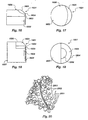
- the drag bit 101 includes a plurality of cutters 102, 103 and 104 which may be arranged as shown in rows emanating generally radially from approximately the center of the bit 105.
- roller cone bit 201 includes three rotatable cones 202, 203 and 204, each of which carries a plurality of cone inserts 205.
- FIG. 3 depicts a side view of a prior art polycrystalline diamond cutter typically used in drag bits.
- the cutter 301 is cylindrical in shape and has a substrate 302 which is typically made of cemented carbide such as tungsten carbide (WC) or other materials, depending on the application.
- the cutter 301 also has a sintered polycrystalline diamond table 303 formed onto substrate 302 by the manufacturing process mentioned above.
- Cutter 301 may be directly mounted to the face of a drag bit, or secured to a stud which is itself secured to the face of a bit.
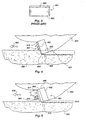
- FIG. 4 depicts a prior art diamond cutter 401, such as the type depicted in FIG. 3, in use on a bit.
- the cutter 401 has a disc-shaped PDC diamond layer or table 402, typically at 0.50 mm to 0.76 mm (0.020 to 0.030) inches thickness (although as noted before, thicker tables have been attempted), sintered onto a tungsten carbide substrate 403.
- the cutter 401 is installed on a bit 404. As the bit 404 with cutter 401 move in the direction indicated by arrow 405, the cutter 401 engages rock 406, resulting in shearing of the rock 406 by the diamond layer 402 and sheared rock 407 sliding along the cutting face 410 and away from the cutter 401.
- the sheared rock 407 may be very long strips, while in non-plastic formations, the sheared rock 407 may comprise discrete particles, as shown.
- the cutting action of the cutter 401 results in a cut of depth "D" being made in the rock 406. It can also be seen from the figure that on the trailing side of the cutter 401 opposite the cut, both diamond layer 402 and substrate or stud 403 are present within the depth of cut D. This has several negative implications. It has been found that prior art cutters tend to experience abrasive and erosive wear on the substrate 403 within the depth of cut D behind the diamond layer or table 402 under certain cutting conditions. This wear is shown at reference numeral 408.
- wear 408 causes support against bending stresses for the diamond layer 402 to be reduced, and the diamond layer 402 will prematurely spall, crack or break. This propensity to damage is enhanced by the high unit stresses experienced at cutting edge 409 of cutting face 410.
- the cutting face diamond layer 402 which is very hard but also very brittle, is supported within the depth of cut D not only by other diamond within the diamond layer 402, but also by a portion of the stud or substrate 403.
- the substrate is typically tungsten carbide and is of lower stiffness than the diamond layer 402. Consequently, when severe tangential forces are placed on the diamond layer 402 and the supporting substrate 403, the diamond layer 402, which is éxtremely weak in tension and takes very little strain to failure, tends to crack and break when the underlying substrate 403 flexes or otherwise "gives.”
- the depth of the diamond layer should be in the range of 0.50 mm to 0.76 mm (0.020 to 0.030 inch) for ease of manufacture and a perceived resistance to chipping and spalling. It was generally believed in the prior art that use of a diamond layer greater than 0.89 mm (0.035 inches)would result in a cutter highly susceptible to breakage, and which would thus have a very short service life.
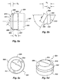
- FIGS. 5a through 5d depict an end view, a side view, an enlarged side view and a perspective view, respectively, of one embodiment of the invented cutter.
- the cutter 501 is of a shallow frustoconical configuration and includes a circular diamond layer or table 502 (e.g. polycrystalline diamond) bonded (i.e. sintered) to a cylindrical substrate 503 (e.g. tungsten carbide).
- the interface between the diamond layer and the substrate is, as shown, comprised of mutually parallel ridges separated by valleys, with the ridges and valleys extending laterally across cutter 501 from side to side.
- a circular diamond layer or table 502 e.g. polycrystalline diamond
- substrate 503 e.g. tungsten carbide
- the interface between the diamond layer and the substrate is, as shown, comprised of mutually parallel ridges separated by valleys, with the ridges and valleys extending laterally across cutter 501 from side to side.
- many other interface geometries are known in the
- the diamond layer 502 is of a thickness T 1 .”
- the substrate 503 has a thickness "T 2.
- the diamond layer 502 includes rake land 508 with a rake land angle ⁇ relative to the side wall 506 of the diamond layer 502 (parallel to the longitudinal axis or center line 507 of the cutter 501) and extending forwardly and radially inwardly toward the longitudinal axis 507.
- the rake land angle ⁇ in the preferred embodiment is defined as the included acute angle between the surface of rake land 508 and the side wall 506 of the diamond layer which, in the preferred embodiment, is parallel to longitudinal axis 507.
- the rake land angle ⁇ is preferred for the rake land angle ⁇ to be in the range of 10° to 80°, but it is most preferred for the rake land angle ⁇ to be in the range of 30° to 60°. However, it is believed to be possible to utilize rake land angles outside of this range and still produce an effective cutter which employs the structure of the invention.
- the width w 1 of the rake land 508 should be at least about 1.27 mm (0.050 inches), measured from the inner boundary of the rake land (or the center of the cutting face, if the rake land extends thereto) to the cutting edge along or parallel to (e.g., at the same angle) to the actual surface of the rake land.
- the direction of measurement, if the cutting face is circular, is generally radial but at the same angle as the rake land (see FIG. 6). It may also be desirable that the width of the rake land (or height, looking head-on at a moving cutter mounted to a bit) be equal to or greater than the design DOC, although this is not a requirement of the invention.
- Diamond layer 502 also includes a cutting face 513 having a flat central area 511 radially inward of rake land, and a cutting edge 509. Between the cutting edge 509 and the substrate 503 resides a portion or depth of the diamond layer referred to as the base layer 510, while the portion or depth between the flat central area 511 of cutting face 513 and the base layer 510 is referred to as the rake land layer 512.
- the central area 511 of cutting face 513 is a flat surface oriented perpendicular to longitudinal axis 507.
- a convex cutting face area such as that described in U.S. Patent No. 5,332,051 to Knowlton. It is also possible to configure such that the land 508 surface of revolution defines a conical point at the center of the cutting face 513.
- the preferred embodiment of the invention is that depicted in FIGS. 5a-5d.
- the thickness T 1 of the diamond layer 502 is preferably in the range of 1.78 mm to 3.81 mm (0.070 to 0.150 inch), with a most preferred range of 2.03 mm to 2.54 mm (0.080 to 0.100 inch). This thickness results in a cutter which, in the invented configuration, has substantially improved impact resistance, abrasion resistance and erosion resistance.
- the base layer 510 thickness T 3 is approximately 1.27 mm (0.050 inch) as measured perpendicular to the supporting face of the substrate, parallel to axis 507.
- the rake land layer 512 is approximately 0.76 mm to 1.27 mm (0.030 to 0.050) inch thick and the rake angle ⁇ of the land 508 as shown is 65° but may, as previously noted, vary.
- the boundary 515 of the diamond layer and substrate to the rear of the cutting edge should lie at least, 0.38 mm (0.015 inch) longitudinally to the rear of the cutting edge and, in the embodiment of FIGS. 5, this distance is substantially greater.
- the aforementioned cutting edge to interface distance is at least highly desirable to ensure that the area of highest residual stress (i.e. the area to the rear of the location where the cutting edge of the cutter contacts the formation being cut) is not subject to early point loading, and to ensure that an adequate, rigid mass of diamond and substrate material supports the line of high loading stress.
- the diameter of the cutter 501 depicted is approximately 19 mm (0.750 inches), and the thickness of the substrate 503 T 2 is approximately 6 mm to 5.5 mm (0.235 to 0.215 inches), although these two dimensions are not critical and larger or smaller diameter cutters with substrates of greater longitudinal extent are contemplated as within the scope of the invention.
- cutters of approximately 13.4 mm (0.529 inch) and of substrate thicknesses ranging from about 5 mm to 12.7 mm (0.20 inch to about 0.50 inch) have also been fabricated in accordance with the present invention.
- the sidewall 517 of the cutter 501 is parallel to the longitudinal axis 507 of the cutter.
- angle ⁇ equals angle ⁇
- cutters of the present invention need not be circular or even symmetrical in cross-section, and the cutter sidewall may not always parallel the longitudinal axis of the cutter.
- the rake land angle may be set as angle ⁇ or as angle ⁇ , depending upon cutter configuration and designer preference.
- the significant aspect of the invention regarding angular orientation of the rake land is the presentation of the rake land to the formation of an effective angle to achieve the advantages of the invention.
- FIGS. 5a through 5d Another optional but desirable feature of the embodiment of the invention depicted in FIGS. 5a through 5d is the use of a low friction finish on the cutting face 511, including rake land 508.
- the preferred low friction finish is a polished mirror finish which has been found to reduce friction between the diamond layer 502 and the formation material being cut and to enhance the integrity of the cutting face surface.
- the reader is directed to U.S. Patent No. 5,447,208 issued to Lund et al. for additional discussion and disclosure of polished superabrasive cutting faces.
- FIGS. 5a through 5d and to the inventive cutter in general is the use of a small peripheral chamfer or radius at the cutting edge as taught by the prior art to increase the durability of the cutting edge while running into the borehole and at the inception of drilling, at least along the portion which initially contacts the formation.
- the inventors have, to date, however, not been able to demonstrate the necessity for such a feature in testing.
- the cutting edge may also be optionally honed in lieu of radiusing or chamfering, but again the necessity for such feature has yet to be demonstrated.
- FIG. 5a Another optional cutter feature usable in the invention feature depicted in broken lines in FIG. 5a is the use of a backing cylinder 516 face-bonded to the back of substrate 503.
- This design permits the construction of a cutter having a greater dimension (or length) along its longitudinal axis 507 to provide additional area for bonding (as by brazing) the cutter to the bit face, and thus to enable the cutter to withstand greater forces in use without breaking free of the bit face.
- Such an arrangement is well known in the art, and disclosed in U.S. Patent 4,200,159.
- the presence or absence of such a backing cylinder does not affect the durability or wear characteristics of the inventive cutter.
- FIG. 6 depicts an embodiment of the invented cutter 601 in use on a bit 650.
- the cutter 601 has a diamond layer 602 sintered onto a tungsten carbide substrate 603.
- the diamond layer 602 has a land 608 which has a rake angle ⁇ with respect to side wall 606.
- the cutter 601 has a cutting face 613 with a central flat area 611. Cutting face 613 cuts the rock 660, contacting it at cutting edge 615.
- the cutter 601 cuts into rock 660 resulting in rock particles or chips 680 sliding across the cutter face 613.
- the cutting action of the cutter 601 results in a cut being made in the rock 660, the cut having depth "D 12 .” It can also be seen from the figure that on the trailing side of the diamond layer 602 opposite the cut behind the cutting edge 615, there is diamond material extending contiguously behind the cutting edge 615 for DOC D 12 .
- the inventors believe that the cutting action that takes place when the invented cutter is used may be more like a grinding action responsive to rapid changes in strain rates in the formation being cut as the cutter passes, as compared to a shearing action which is thought to occur when prior art cutters are used.
- the inventors also believe that a cutter employing the invented structural features may not necessarily undergo the self-sharpening phenomena mentioned in conjunction with FIG. 4.
- the thickened diamond table and rake land can serve to isolate the substrate of the cutter from erosion that permits self-sharpening of the diamond layer.
- the thickened diamond table and the rake land also have the effect of substantially isolating the diamond table/substrate interface from the cutting loads, and provide a higher stress gradient with respect to such loads.
- the cutter 701 which, for exemplary purposes is shown mounted to a stud 702, may include a substrate 703, and diamond layer 704 with cutting edge 705. As the cutting edge 705 is propelled against the rock 706 by forward movement of the stud 702 as indicated by arrow 707, a force is applied against the diamond layer 704 by the rock 706 as indicated by the resultant force vector F R1 as indicated by reference numeral 708.
- the cutter 701 is actually moving in a shallow helical path and the cutting face 705 contacts the rock 706 at a point on a horizontal line 709 that is tangent to the circle in which the cutting face 705 moves.
- the resultant force vector F R1 is applied against the cutting face 710 at an angle ⁇ , the angle ⁇ being measured from the horizon as indicated by line 709 (which is the same as a line tangent to the circle in which the cutting face 705 moves).
- the resultant force vector F R1 is a reactive force vector comprised of two separate force components: F t which is a tangential force created by bit rotation and cutter 701 moving against the rock 706 during cutting (including torque on bit, shear force to fail the rock, and friction between the cutter and the formation, although the latter is relatively small), F t being oriented parallel to line 709 and F n which is a normal force attributable to weight on bit and exerted perpendicular to F t and toward the rock 706.
- F R1 is the reactive force vector applied to cutting face 710 by the formation rock 706 in response to F t and F n .
- the resultant force vector F R1 is oriented in a direction within a range generally parallel to the longitudinal axis A L of cutter 701 and along the sidewall trailing cutting edge 705, depending on the relative magnitude of F t and F n .
- the resultant force vector F R1 is oriented generally parallel to A L that force is being borne by the diamond layer 704, the substrate 703 and the interface therebetween in an area that includes substantial residual tensile stresses from the manufacturing process. Consequently, prior art cutters tended to spall, crack, chip and break regardless of the strength of the stud or substrate used. This propensity is due, as previously noted, to high bonding stresses, high F n (spalling), high F t (fracture) and the orientation of F R1 which increases net effective stresses.
- the cutter 801 which is mounted to stud 802, includes substrate 803, and diamond layer 804 with cutting face 810 including central area 12, rake land 814 and cutting edge 805.
- a force is applied against the diamond layer 804 by the rock 806 as indicated by the resultant force vector range F R2 (reference numeral 808).
- the cutter 801 is actually moving in a circular direction along a shallow helical path and the cutting edge 805 contacts the rock 806 at a point on a horizontal line 809 that is tangent to the circle in which the cutting face 805 moves.
- the resultant force vector F R2 is applied against the cutting face 810 at an angle ⁇ , the angle ⁇ being measured from the horizon as indicated by line 809 (which is the same as a line tangent to the circle in which the cutting face 805 moves).
- the resultant force vector F R2 is a force vector created by two separate force components F t and F n , as described above with respect to FIG. 7.
- the diamond layer 804 exhibits a greatly lengthened service life and seldom fails in a catastrophic manner, as frequently occurs with standard cutters. Under very long term use, it has been found that the cutting face 810 of the invented cutter with a large rake land will tend to wear, but the serious prior art problems with catastrophic failures have been substantially reduced.
- the rake land of the invention lowers the unit stress on the cutting face by providing an enlarged bearing area B2.
- a thick diamond table is combined with the large rake land, a large stress gradient is provided across the diamond table and the result is an extremely long lasting and durable cutter.
- the thicker diamond table also generally provides a stiffer cutting structure and reduces the overall propensity of cracks in the diamond table to propagate to the point of cutter failure.
- the relative portion of the force vector acting on the cutting face in a direction tending to bend the diamond table is reduced responsive to the angled rake land.
- a polycrystalline diamond cutter according to the invention of about 2.28 mm (0.090 inch) diamond table thickness, having a 45° rake land angle and about 0.88 mm (0.035) diamond table thickness (base layer thickness) between the cutting edge and the table substrate interface, of identical diamond structure to all but the first cutter tested, of the same size as the other cutters, without a chamfered cutting edge, a bar stiffening structure, a tapered substrate or a polished rake land (the center of the cutting face, however, being polished) but of the configuration of the invention, cut almost 0.377 m 3 (23,000 cubic inches) of rock without either catastrophic failure or reaching its wear limit.
- the inventors also performed finite element analysis of prior art polycrystalline diamond cutters and of the invented cutter with a large rake land. They found that on prior art cutters, there is a region of very high residual stress in the diamond table/substrate interface area near the periphery of the cutter immediately behind the cutting edge. Prior art cutters exhibit spalling, cracking, chipping and breaking of the diamond layer ahead of the residual stress area, including at the cutting face, due to high unit stresses and orientation of the force vector acting on the cutting edge toward this high-stress area. This, of course, results in decreased service life and catastrophic failures of prior art cutters. The finite element analysis that the inventors performed on the invented cutter showed that the location in the substrate which under high residual stress component was far less highly stressed in the invented cutter due to thickness of the diamond table and reorientation of cutting load components by the rake land.
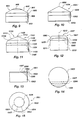
- a cylindrical cutter 901 with a diamond table 902 atop a substrate 903 is depicted.
- Cutting face 904 includes a rake land 905 extending to a center, convex area 906.
- Cutting edge 908 is longitudinally spaced from substrate 903.
- the cutter is a cylindrical cutter with a conical proximal or loading end.
- the cutter 1001 has a diamond table 1002 atop a substrate 1003.
- the diamond table has a cutting edge 1006 and a rake land 1004. It can be seen from the figure that the rake land 1004 occupies the entire proximal or cutting face of the cutter 1001 and terminates in a conical point 1005.
- FIG. 11 depicts an alternative embodiment of the invention.
- the cutter 1101 has a diamond table 1102 atop a substrate 1103.
- the diamond table 1102 includes a first side wall 1104 that may be generally parallel either to the substrate side wall 1105 or to the longitudinal axis 1106 of the cutter.
- the diamond table also has a rake cutting edge 1107 where the rake land 1108 meets the first side wall.
- the cutting edge 1107 or the interface between the rake land and the first side wall 1104 forms the outer boundary of the rake land 1108.
- the rake land 1108 has an inner boundary 1109 which is the outer boundary of the central area of cutting face 1110.
- the rake land 1108 in this embodiment may be referred to as a second side wall which is formed at an obtuse angle to the first side wall.
- a third side wall 1111 formed at an obtuse angle to the second side wall or rake land 1108 proceeds to a conical point 1112 at the extreme proximal end of the cutter 1101.
- the cutter 1201 has a diamond layer 1202 atop a substrate 1203.
- the substrate 1203 is radiused or forms a dome 1208 beneath the diamond layer 1202.
- the diamond layer 1202 has a sidewall 1209 that is shown as being generally parallel to the substrate sidewall 1211 and to the longitudinal axis 1210 of the cutter 1201, but which could be angled otherwise.
- the diamond layer 1202 also includes a cutting edge 1204, a rake land 1205 and a central cutting face area 1207.
- the area 1207 is that portion of the proximal end of the diamond table 1202 within the inner boundary 1206 of the rake land.
- FIG. 13 depicts a prior art cutter 1301 having a diamond table 1303 atop a substrate 1302. It can be seen from the figure that when the prior art cutter 1301 is new, it has a sharp cutting edge 1304 at the outer periphery of the diamond table 1303. As the cutter 1301 wears, it loses its sharp cutting edge 1304 and tends to wear into the substrate 1302 in a rounded shape as illustrated by a progression denoted by reference numerals 1305, 1306 and 1307.
- the prior art cutter 1301 is also depicted.
- the cutter is shown from its diamond table 1303 or proximal end.
- a wear flat developing on the cutter 1301, primarily in the substrate 1302, is depicted using reference numerals 1305, 1306 and 1307 in progression.
- the worn prior art cutter does not assume the physical configuration of the invented cutter with large wear land. Instead, the prior art cutter forms an ever-longer, ever-wider wear flat primarily in the substrate material behind the diamond table. Further, the worn cutter of FIGS. 13 and 14 has a physical configuration determined by dynamic forces occurring within the bore hole and beyond the reasonable control of the user. Thus, prior art cutters which become worn achieve a particular physical configuration because of many random and uncontrollable factors, and it is not possible to wear a prior art cutter into a given desired configuration. As a result, the prior art cutter may have an incidental wear flat present on its exterior, but its configuration after it is worn is out of the control of the user.
- FIG. 15 an end view of one embodiment of the invented cutter 1501 from its diamond table 1502 or proximal end is provided.
- the cutting edge 1503, rake land 1504, inner boundary 1505 of the rake land, and central cutting face area 1506 are all depicted.
- the cutter 1501 As the cutter 1501 is used, it will develop a wear flat 1507 that is only slightly broader adjacent the cutting edge 1503 or periphery of the cutter (i.e. adjacent the cutter wall) than it is at the inner portion of the rake land known as the inner boundary 1505. Comparing the wear flat depicted in FIG. 15 to that of FIGS. 13 and 14, the reader can gain more appreciation of the advantageous dynamics of cutter shape over time provided by the invention.
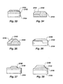
- FIGS. 16 and 17 depict an alternative embodiment of the invention.
- the cutter 1601 has a substrate 1602 onto which a diamond table 1603 is formed.
- the diamond table 1603 has a cutting edge 1604, and a non-circular rake land 1605 along one side of a cutting face 1606.
- FIG. 17 shows an end view of the cutter 1601 from its proximal end (diamond table end). It can be seen from FIGS. 16 and 17 that the cutter 1601 has a rake land 1605 on only one side or along a portion of its lateral periphery. It is preferred to construct a cylindrical cutter with a rake land on the diamond table about its entire periphery.
- FIGS. 18 and 19 depict another embodiment of the invention.
- FIGS. 18 and 19 shows a cutter 1801 which includes a substrate 1802 and a diamond table 1803.
- the cutter 1801 has a cutting edge 1804, a rake land 1805 and a central or inner cutting face area 1806.
- FIG. 33 depicts an end view of the cutter 1801 from its proximal (diamond table end).
- This cutter 1801 is in effect a half cutter, because while the substrate 1802 includes a full cylindrical portion 1807 to accommodate installing the cutter 1801 into a receptacle on a bit, the cutter 1801 has a diamond table 1803 that is a half cylinder.
- the substrate 1802 has a table supporting portion 1808 which is part of the full cylindrical portion 1807.
- This cutter does not accommodate full rotation about its longitudinal axis in a receptacle on a bit in order to maximize the useful life of the cutter, but it includes the invented structure and will provide the user with the advantages of the invention.
- the cutter could be a half cutter, a third cutter, a quarter cutter or any other portion of a full cylindrical cutter.
- a cutter which embodies the inventive concept could be made that is not cylindrical in shape.
- a cutter with a thick diamond table and a large wear land it is possible for a cutter with a thick diamond table and a large wear land to be constructed that is square, rectangular, triangular, pentagonal, hexagonal, heptagonal, octagonal, otherwise shaped as an n-sided polygon (where n is an integer), oval, elliptical, or shaped otherwise in a cross section taken orthogonal to the longitudinal axis of the cutter.
- FIG. 20 depicts a side view of the invented cutters of two different physical configurations, 2001 and 2002, in use on a roller cone of a rock bit.
- FIGS. 21-38 depict further alternative embodiments of the cutter of the invention.
- Diamond tables are identified by reference numeral 2102, substrates by 2104 and rake lands by 2106.
- the inventors believe that the invented cutter will, when in use in a bore hole, contact the formation being cut with a longitudinally-extending, arc-shaped area of the cutter along the cutting edge.
- new prior art cutters contacted the formation being cut at a single point or transversely-extending line on the cutting edge.
- the longitudinal, arc-shaped region of contact on the rake land between the invented cutter and the formation distributes the force of impact against the cutter over a larger superabrasive surface in the invented cutter than in the prior art, hence lowering unit stress on the cutter. This distribution of forces over a larger surface area, in combination with reorientation of F R and enlargement of the stress gradient due to use of a thicker diamond table, increases the impact resistance of the invented cutter.
- the invented cutter improves cutter wear performance by providing a cutter which has been found to cut a greater volume of subterranean formation than a typical prior art cutter of similar diameter and composition.
- the invented cutter has also been found to have greater impact resistance than prior art cutters.
- the invented cutter also has improved erosion resistance and abrasion resistance compared to prior art cutters. These improved performance attributes are believed to be attributable primarily to the use of a large rake land.
- the diamond table may be made from polycrystalline diamond or thermally stable polycrystalline diamond, depending upon the application.
- a cutting table or compact of any of the following types could be used in the cutter: diamond film (including CVD), cubic boron nitride, and a structure predicted in the literature as C 3 N 4 being equivalent to known superabrasive materials. Additional suitable materials may exist and be used to form a cutter table as well.
- the cutting table would serve the same function as the diamond table, and would have the same general structural features as the diamond table in the invented cutter.
- a cutter which uses material other than diamond in the cutter table and includes other features of the invention is considered a cutter of the invention.
- cutters of the invention be manufactured using the manufacturing process described in the Background of this document. This includes compressing diamond particles adjacent a suitable substrate material under high pressure and high temperature conditions to form a diamond table that is sintered to the substrate.
- a suitable substrate material such as tungsten carbide (WC)
- WC tungsten carbide
- the manufacturing process may need to be modified appropriately.
- numerous substrates other than tungsten carbide may be used to make the invented cutter.
- Appropriate substrate materials include any cemented metal carbide such as carbides of tungsten (W), niobium (Nb), zirconium (Zr), vanadium (V), tantalum (Ta), titanium (Ti), tungsten Ti) and hafnium (Hf).
- cemented metal carbide such as carbides of tungsten (W), niobium (Nb), zirconium (Zr), vanadium (V), tantalum (Ta), titanium (Ti), tungsten Ti) and hafnium (Hf).
- a cutter is provided that has a large or wide rake land that increases the effective back rake of the cutter as it is presented to the formation by the bit face.
- the actual angle of contact of the cutting face with the formation (and thus the effective back rake) is determined in part by the angle of the wide rake land on the cutter. This permits adjustments to cutter effective back rake without altering the orientation of a cutter on the bit face, by employing cutters according to the invention having different rake land angles.
Claims (40)
- Elément de coupe inutilisé destiné à être utilisé sur un trépan pour le forage de formations souterraines, ledit élément de coupe comportant un axe longitudinal et comprenant:un volume de matériau superabrasif (502), englobant:une face de coupe (513) s'étendant de manière généralement transversale audit axe longitudinal (507);une arête de coupe (509) au niveau d'une périphérie de ladite face de coupe (513);une limite arrière (515) pratiquement coextensive sur la périphérie avec ladite arête de coupe(509) et s'étendant derrière celle-ci sur une distance longitudinale (T3) non inférieure à environ 0,38 mm (0,015 pouce);au moins une partie inclinée (508) sur ladite face de coupe (513), s'étendant vers l'avant, vers l'intérieur et à l'écart de l'arête de coupe, à un angle aigu par rapport audit axe longitudinal (507) et ayant une épaisseur mesurée parallèlement audit axe longitudinal (507), non inférieure à environ 0,76 mm (0,030 pouce); etledit volume de matériau superabrasif (502) ayant une épaisseur (T1), mesurée parallèlement audit axe longitudinal (507), près de ladite arête de coupe (509), non inférieure à environ 1,78 mm (0,070 pouce).
- Elément de coupe selon la revendication 1, dans lequel ladite épaisseur du matériau superabrasif (502) est pratiquement coextensive sur la périphérie avec ladite arête de coupe (509).
- Elément de coupe selon l'une quelconque des revendications précédentes, dans lequel ladite au moins une partie inclinée (508) englobe une largeur (W1) s'étendant de ladite arête de coupe (509) vers l'avant et vers l'intérieur le long d'une surface de ladite au moins une partie inclinée (508) sur une distance non inférieure à environ 1,27 mm (0,050 pouce), mesurée le long de la surface de ladite au moins une partie inclinée (508).
- Elément de coupe selon l'une quelconque des revendications précédentes, dans lequel ledit matériau superabrasif (502) englobe une paroi latérale (506) entre ladite arête de coupe (509) et ladite limite arrière (515).
- Elément de coupe selon la revendication 4, dans lequel ladite paroi latérale est pratiquement parallèle audit axe longitudinal (507).
- Elément de coupe selon les revendications 4 ou 5, dans lequel ladite au moins une partie inclinée (508) est orientée à un angle compris entre environ 10° et 80° par rapport à ladite paroi latérale.
- Elément de coupe selon les revendications 4 ou 5, dans lequel ladite au moins une partie inclinée (508) est orientée à un angle compris entre environ 30° et 60° par rapport à ladite paroi latérale.
- Elément de coupe selon l'une quelconque des revendications précédentes dans lequel ledit élément de coupe englobe une périphérie arquée au niveau de ladite arête de coupe (509).
- Elément de coupe selon la revendication 8, dans lequel ladite au moins une partie inclinée est arquée.
- Elément de coupe selon l'une quelconque des revendications précédentes, dans lequel ledit élément de coupe est circulaire, ladite arête de coupe (509) étant arquée et ladite au moins une partie inclinée (508) s'étendant radialement vers l'intérieur en direction dudit axe longitudinal (507).
- Elément de coupe selon l'une quelconque des revendications précédentes, dans lequel ladite au moins une partie inclinée (508) s'étend au moins vers ledit axe longitudinal (507).
- Elément de coupe selon l'une quelconque des revendications précédentes, dans lequel ladite au moins une partie inclinée (508) se situe entre ladite arête de coupe et une zone centrale de la face de coupe (511).
- Elément de coupe selon la revendication 12, dans lequel au moins une partie de ladite zone centrale de la face de coupe (511) est pratiquement plane.
- Elément de coupe selon la revendication 12, dans lequel au moins une partie de ladite zone centrale de la face de coupe est convexe.
- Elément de coupe selon la revendication 12, dans lequel au moins une partie de ladite zone centrale de la face de coupe est concave.
- Elément de coupe selon l'une quelconque des revendications précédentes, dans lequel une partie dudit volume de matériau superabrasif (502) est fixée sur une partie dudit élément de substrat (503).
- Elément de coupe selon la revendication 16, dans lequel ladite partie dudit élément de substrat (503) est fixée sur ladite partie dudit volume de matériau superabrasif (502) près de ladite limite arrière (515).
- Elément de coupe selon les revendications 16 ou 17, dans lequel ladite partie dudit élément de substrat (503) est fixée sur ladite partie dudit volume de matériau superabrasif (502) sur une partie arrière de ladite arête de coupe (509).
- Elément de coupe selon l'une quelconque des revendications 16 à 18, dans lequel ledit élément de substrat (503) s'étend latéralement derrière ledit volume de matériau superabrasif (502), au moins jusqu'à ladite arête de coupe (509).
- Elément de coupe selon l'une quelconque des revendications 16 à 19, dans lequel ledit volume de matériau superabrasif et ledit élément de substrat sont fixés le long d'une limite pratiquement plane.
- Elément de coupe selon l'une quelconque des revendications 16 à 19, dans lequel ledit volume de matériau superabrasif (502) et ledit élément de substrat (503) sont fixés le long d'une limite composée de nervures mutuellement parallèles séparées par des creux.
- Elément de coupe selon l'une quelconque des revendications 16 à 19, dans lequel ledit élément de substrat déborde dans ledit volume de matériau superabrasif.
- Elément de coupe selon la revendication 22, dans lequel une partie en saillie dudit élément de substrat dans ledit volume de matériau superabrasif a une forme convexe.
- Elément de coupe selon la revendication 22, dans lequel une partie en saillie dudit élément de substrat dans ledit volume de matériau superabrasif a une forme en tronc de cône.
- Elément de coupe selon l'une quelconque des revendications 16 à 19, dans lequel ledit volume de matériau superabrasif déborde dans ledit élément de substrat.
- Elément de coupe selon la revendication 25, dans lequel une partie en saillie dudit volume de matériau superabrasif dans ledit élément de substrat est conique.
- Elément de coupe selon l'une quelconque des revendications 16 à 19, englobant en outre une ouverture s'étendant longitudinalement à travers ledit volume de matériau superabrasif et ledit élément de substrat.
- Elément de coupe selon l'une quelconque des revendications 16 à 19, dans lequel une partie dudit élément de substrat s'étend vers l'avant vers un emplacement adjacent à une partie avant de ladite face de coupe.
- Elément de coupe selon l'une quelconque des revendications précédentes, dans lequel ladite au moins une partie inclinée (508) est pratiquement coextensive avec ladite arête de coupe (509).
- Elément de coupe selon l'une quelconque des revendications 1 à 28, dans lequel ladite au moins une partie inclinée est agencée latéralement vers l'intérieur de ladite arête de coupe et est discontinue par rapport à celle-ci.
- Elément de coupe selon la revendication 30, englobant en outre une surface de la face de coupe pratiquement transversale audit axe longitudinal s'étendant entre ladite arête de coupe et ladite au moins une partie inclinée.
- Elément de coupe selon l'une quelconque des revendications précédentes, dans lequel ladite au moins une partie inclinée comprend plusieurs parties inclinées.
- Elément de coupe selon la revendication 32, dans lequel au moins deux desdites plusieurs parties inclinées sont annulaires.
- Elément de coupe selon la revendication 33, dans lequel au moins deux desdites plusieurs parties inclinées sont annulaires.
- Elément de coupe selon l'une quelconque des revendications précédentes, dans lequel ladite au moins une partie inclinée a une épaisseur, mesurée parallèlement audit axe longitudinal, non supérieure à environ 0,050 pouce.
- Elément de coupe selon l'une quelconque des revendications précédentes, dans lequel l'épaisseur (T1) dudit volume de matériau superabrasif (502) est comprise dans l'intervalle allant de 1,78 mm à 3,81 mm (0,070 pouce à 0,150 pouce).
- Elément de coupe selon l'une quelconque des revendications précédentes, dans lequel l'épaisseur (T1) dudit volume de matériau superabrasif (502) est comprise dans l'intervalle allant de 2,03 mm à 2,54 mm (0,080 pouce à 0,100 pouce).
- Dispositif destiné au forage de formations souterraines, comprenant:un corps présentant une surface externe comportant au moins un élément de coupe qui y et fixé, ledit au moins un élément de coupe (501) comportant un axe longitudinal (507) et comprenant un volume de matériau superabrasif (502), englobant:une face de coupe généralement transversale audit axe longitudinal dudit élément de coupe;une arête de coupe (513) au niveau d'une périphérie de ladite face de coupe;une limite arrière (515) pratiquement coextensive sur la périphérie avec ladite arête de coupe (509) et s'étendant derrière celle-ci sur une distance longitudinale non inférieure à environ 0,38 mm (0,015 pouce);au moins une partie inclinée (508) sur ladite face de coupe (513), s'étendant vers l'avant, vers l'intérieur et à l'écart de celle-ci, à un angle aigu par rapport audit axe longitudinal (507), ayant une épaisseur, mesurée parallèlement audit axe longitudinal (507), non inférieure à environ 0,76 mm (0,030 pouce);ledit volume de matériau superabrasif (502) ayant une profondeur, mesurée parallèlement audit axe longitudinal (507), près de ladite extrémité de coupe (509) et pratiquement coextensive sur la périphérie avec elle-ci, non inférieure à environ 1,78 mm (0,070 pouce).
- Dispositif selon la revendication 38, dans lequel ledit corps est sélectionné dans le groupe comprenant: un corps de trépan à lames, un corps de trépan de cône à molettes, un cône pour un trépan de cône à molettes, un corps de trépan de mine, un alésoir, un stabilisateur, un raccord d'outil, un noeud d'usure et un outil de guidage.
- Dispositif selon les revendications 38 ou 39, dans lequel ledit élément de coupe (501) comprend en outre les caractéristiques selon l'une quelconque des revendications 2 à 38.
Applications Claiming Priority (3)
| Application Number | Priority Date | Filing Date | Title |
|---|---|---|---|
| US602076 | 1996-02-15 | ||
| US08/602,076 US5706906A (en) | 1996-02-15 | 1996-02-15 | Superabrasive cutting element with enhanced durability and increased wear life, and apparatus so equipped |
| PCT/US1997/002288 WO1997030263A1 (fr) | 1996-02-15 | 1997-02-13 | Foret au diamant polycristallin presentant une meilleure durabilite et resistance a l'usure |
Publications (2)
| Publication Number | Publication Date |
|---|---|
| EP0891467A1 EP0891467A1 (fr) | 1999-01-20 |
| EP0891467B1 true EP0891467B1 (fr) | 2003-06-18 |
Family
ID=24409872
Family Applications (1)
| Application Number | Title | Priority Date | Filing Date |
|---|---|---|---|
| EP97905951A Expired - Lifetime EP0891467B1 (fr) | 1996-02-15 | 1997-02-13 | Foret au diamant polycristallin presentant une meilleure durabilite et resistance a l'usure |
Country Status (4)
| Country | Link |
|---|---|
| US (3) | US5706906A (fr) |
| EP (1) | EP0891467B1 (fr) |
| AU (1) | AU2272297A (fr) |
| WO (1) | WO1997030263A1 (fr) |
Families Citing this family (210)
| Publication number | Priority date | Publication date | Assignee | Title |
|---|---|---|---|---|
| US7494507B2 (en) * | 2000-01-30 | 2009-02-24 | Diamicron, Inc. | Articulating diamond-surfaced spinal implants |
| US7396505B2 (en) * | 1994-08-12 | 2008-07-08 | Diamicron, Inc. | Use of CoCrMo to augment biocompatibility in polycrystalline diamond compacts |
| US6514289B1 (en) | 2000-01-30 | 2003-02-04 | Diamicron, Inc. | Diamond articulation surface for use in a prosthetic joint |
| US6494918B1 (en) | 2000-01-30 | 2002-12-17 | Diamicron, Inc. | Component for a prosthetic joint having a diamond load bearing and articulation surface |
| US6596225B1 (en) | 2000-01-31 | 2003-07-22 | Diamicron, Inc. | Methods for manufacturing a diamond prosthetic joint component |
| US6402787B1 (en) | 2000-01-30 | 2002-06-11 | Bill J. Pope | Prosthetic hip joint having at least one sintered polycrystalline diamond compact articulation surface and substrate surface topographical features in said polycrystalline diamond compact |
| US6800095B1 (en) | 1994-08-12 | 2004-10-05 | Diamicron, Inc. | Diamond-surfaced femoral head for use in a prosthetic joint |
| US6676704B1 (en) | 1994-08-12 | 2004-01-13 | Diamicron, Inc. | Prosthetic joint component having at least one sintered polycrystalline diamond compact articulation surface and substrate surface topographical features in said polycrystalline diamond compact |
| US6170576B1 (en) | 1995-09-22 | 2001-01-09 | Weatherford/Lamb, Inc. | Mills for wellbore operations |
| US5984005A (en) * | 1995-09-22 | 1999-11-16 | Weatherford/Lamb, Inc. | Wellbore milling inserts and mills |
| US5908071A (en) * | 1995-09-22 | 1999-06-01 | Weatherford/Lamb, Inc. | Wellbore mills and inserts |
| US6571891B1 (en) | 1996-04-17 | 2003-06-03 | Baker Hughes Incorporated | Web cutter |
| US5881830A (en) * | 1997-02-14 | 1999-03-16 | Baker Hughes Incorporated | Superabrasive drill bit cutting element with buttress-supported planar chamfer |
| US6733365B1 (en) * | 1997-08-12 | 2004-05-11 | Arizona Board Of Regents | Method and apparatus for hard machining |
| US5957228A (en) * | 1997-09-02 | 1999-09-28 | Smith International, Inc. | Cutting element with a non-planar, non-linear interface |
| US5928071A (en) * | 1997-09-02 | 1999-07-27 | Tempo Technology Corporation | Abrasive cutting element with increased performance |
| US6672406B2 (en) | 1997-09-08 | 2004-01-06 | Baker Hughes Incorporated | Multi-aggressiveness cuttting face on PDC cutters and method of drilling subterranean formations |
| US6321862B1 (en) * | 1997-09-08 | 2001-11-27 | Baker Hughes Incorporated | Rotary drill bits for directional drilling employing tandem gage pad arrangement with cutting elements and up-drill capability |
| US6173797B1 (en) | 1997-09-08 | 2001-01-16 | Baker Hughes Incorporated | Rotary drill bits for directional drilling employing movable cutters and tandem gage pad arrangement with active cutting elements and having up-drill capability |
| US5960896A (en) * | 1997-09-08 | 1999-10-05 | Baker Hughes Incorporated | Rotary drill bits employing optimal cutter placement based on chamfer geometry |
| US6230828B1 (en) | 1997-09-08 | 2001-05-15 | Baker Hughes Incorporated | Rotary drilling bits for directional drilling exhibiting variable weight-on-bit dependent cutting characteristics |
| US7000715B2 (en) | 1997-09-08 | 2006-02-21 | Baker Hughes Incorporated | Rotary drill bits exhibiting cutting element placement for optimizing bit torque and cutter life |
| US6006846A (en) * | 1997-09-19 | 1999-12-28 | Baker Hughes Incorporated | Cutting element, drill bit, system and method for drilling soft plastic formations |
| US5944129A (en) * | 1997-11-28 | 1999-08-31 | U.S. Synthetic Corporation | Surface finish for non-planar inserts |
| AU1615499A (en) * | 1997-12-02 | 1999-06-16 | Robert Paul Radtke | Continuous self-sharpening cutting assembly for use with drilling systems |
| US6199645B1 (en) | 1998-02-13 | 2001-03-13 | Smith International, Inc. | Engineered enhanced inserts for rock drilling bits |
| US6460636B1 (en) * | 1998-02-13 | 2002-10-08 | Smith International, Inc. | Drill bit inserts with variations in thickness of diamond coating |
| GB9803096D0 (en) * | 1998-02-14 | 1998-04-08 | Camco Int Uk Ltd | Improvements in preform elements and mountings therefor |
| BE1012975A3 (fr) * | 1998-03-11 | 2001-07-03 | Dresser Ind | Couteau de coupe pour tete de forage ou de carottage et tete equipee de tels couteaux. |
| US6003623A (en) * | 1998-04-24 | 1999-12-21 | Dresser Industries, Inc. | Cutters and bits for terrestrial boring |
| GB9809690D0 (en) * | 1998-05-08 | 1998-07-01 | Camco Int Uk Ltd | Improvements in elements faced with superhard material |
| US5971087A (en) | 1998-05-20 | 1999-10-26 | Baker Hughes Incorporated | Reduced residual tensile stress superabrasive cutters for earth boring and drill bits so equipped |
| US6202772B1 (en) | 1998-06-24 | 2001-03-20 | Smith International | Cutting element with canted design for improved braze contact area |
| US6527069B1 (en) | 1998-06-25 | 2003-03-04 | Baker Hughes Incorporated | Superabrasive cutter having optimized table thickness and arcuate table-to-substrate interfaces |
| US6412580B1 (en) | 1998-06-25 | 2002-07-02 | Baker Hughes Incorporated | Superabrasive cutter with arcuate table-to-substrate interfaces |
| US6105694A (en) * | 1998-06-29 | 2000-08-22 | Baker Hughes Incorporated | Diamond enhanced insert for rolling cutter bit |
| US6220375B1 (en) * | 1999-01-13 | 2001-04-24 | Baker Hughes Incorporated | Polycrystalline diamond cutters having modified residual stresses |
| US6302224B1 (en) | 1999-05-13 | 2001-10-16 | Halliburton Energy Services, Inc. | Drag-bit drilling with multi-axial tooth inserts |
| GB9911139D0 (en) * | 1999-05-14 | 1999-07-14 | Camco Int Uk Ltd | Preform cutting elemenys for rotary drill bits |
| JP3102427B1 (ja) * | 1999-05-18 | 2000-10-23 | 住友電気工業株式会社 | 多結晶ダイヤモンド工具 |
| US6397958B1 (en) | 1999-09-09 | 2002-06-04 | Baker Hughes Incorporated | Reaming apparatus and method with ability to drill out cement and float equipment in casing |
| US6695080B2 (en) | 1999-09-09 | 2004-02-24 | Baker Hughes Incorporated | Reaming apparatus and method with enhanced structural protection |
| US8603181B2 (en) * | 2000-01-30 | 2013-12-10 | Dimicron, Inc | Use of Ti and Nb cemented in TiC in prosthetic joints |
| US20100025898A1 (en) * | 2000-01-30 | 2010-02-04 | Pope Bill J | USE OF Ti AND Nb CEMENTED TiC IN PROSTHETIC JOINTS |
| US6709463B1 (en) | 2000-01-30 | 2004-03-23 | Diamicron, Inc. | Prosthetic joint component having at least one solid polycrystalline diamond component |
| US6408958B1 (en) * | 2000-10-23 | 2002-06-25 | Baker Hughes Incorporated | Superabrasive cutting assemblies including cutters of varying orientations and drill bits so equipped |
| US6550556B2 (en) | 2000-12-07 | 2003-04-22 | Smith International, Inc | Ultra hard material cutter with shaped cutting surface |
| US6513608B2 (en) | 2001-02-09 | 2003-02-04 | Smith International, Inc. | Cutting elements with interface having multiple abutting depressions |
| US6510910B2 (en) | 2001-02-09 | 2003-01-28 | Smith International, Inc. | Unplanar non-axisymmetric inserts |
| US6808031B2 (en) | 2001-04-05 | 2004-10-26 | Smith International, Inc. | Drill bit having large diameter PDC cutters |
| US6655845B1 (en) | 2001-04-22 | 2003-12-02 | Diamicron, Inc. | Bearings, races and components thereof having diamond and other superhard surfaces |
| US6659199B2 (en) | 2001-08-13 | 2003-12-09 | Baker Hughes Incorporated | Bearing elements for drill bits, drill bits so equipped, and method of drilling |
| US6604588B2 (en) | 2001-09-28 | 2003-08-12 | Smith International, Inc. | Gage trimmers and bit incorporating the same |
| US7556668B2 (en) * | 2001-12-05 | 2009-07-07 | Baker Hughes Incorporated | Consolidated hard materials, methods of manufacture, and applications |
| US7036611B2 (en) | 2002-07-30 | 2006-05-02 | Baker Hughes Incorporated | Expandable reamer apparatus for enlarging boreholes while drilling and methods of use |
| US6904983B2 (en) * | 2003-01-30 | 2005-06-14 | Varel International, Ltd. | Low-contact area cutting element |
| US6935444B2 (en) * | 2003-02-24 | 2005-08-30 | Baker Hughes Incorporated | Superabrasive cutting elements with cutting edge geometry having enhanced durability, method of producing same, and drill bits so equipped |
| AR044550A1 (es) * | 2003-05-26 | 2005-09-21 | Shell Int Research | Cabeza de perforacion y sistema y metodo para perforar un pozo de perforacion en una formacion de tierra |
| US6962218B2 (en) * | 2003-06-03 | 2005-11-08 | Smith International, Inc. | Cutting elements with improved cutting element interface design and bits incorporating the same |
| AR044485A1 (es) * | 2003-06-12 | 2005-09-14 | Shell Int Research | Mecha perforadora con percusion, sistema de perforacion que incluye dicha mecha perforadora y un metodo para perforar un pozo |
| US6904984B1 (en) | 2003-06-20 | 2005-06-14 | Rock Bit L.P. | Stepped polycrystalline diamond compact insert |
| US7395882B2 (en) | 2004-02-19 | 2008-07-08 | Baker Hughes Incorporated | Casing and liner drilling bits |
| US20050109546A1 (en) * | 2003-11-26 | 2005-05-26 | Baker Hughes Incorporated | Flat and bevel chipbreaker insert |
| WO2005061181A2 (fr) * | 2003-12-11 | 2005-07-07 | Element Six (Pty) Ltd | Elements abrasifs en diamant polycristallin |
| US8146683B2 (en) * | 2004-02-19 | 2012-04-03 | Baker Hughes Incorporated | Drilling out casing bits with other casing bits |
| US7624818B2 (en) * | 2004-02-19 | 2009-12-01 | Baker Hughes Incorporated | Earth boring drill bits with casing component drill out capability and methods of use |
| US7954570B2 (en) * | 2004-02-19 | 2011-06-07 | Baker Hughes Incorporated | Cutting elements configured for casing component drillout and earth boring drill bits including same |
| US7726420B2 (en) * | 2004-04-30 | 2010-06-01 | Smith International, Inc. | Cutter having shaped working surface with varying edge chamfer |
| US20050247486A1 (en) * | 2004-04-30 | 2005-11-10 | Smith International, Inc. | Modified cutters |
| US7798257B2 (en) * | 2004-04-30 | 2010-09-21 | Smith International, Inc. | Shaped cutter surface |
| RU2398660C2 (ru) * | 2004-05-12 | 2010-09-10 | Бейкер Хьюз Инкорпорейтед | Абразивный элемент для режущего инструмента |
| US20050257963A1 (en) * | 2004-05-20 | 2005-11-24 | Joseph Tucker | Self-Aligning Insert for Drill Bits |
| US7455126B2 (en) * | 2004-05-25 | 2008-11-25 | Shell Oil Company | Percussive drill bit, drilling system comprising such a drill bit and method of drilling a bore hole |
| AU2005262558B8 (en) * | 2004-06-23 | 2008-04-10 | Revision Therapeutics, Inc. | Methods and compositions for treating ophthalmic conditions with retinyl derivatives |
| US7243745B2 (en) * | 2004-07-28 | 2007-07-17 | Baker Hughes Incorporated | Cutting elements and rotary drill bits including same |
| US7360608B2 (en) | 2004-09-09 | 2008-04-22 | Baker Hughes Incorporated | Rotary drill bits including at least one substantially helically extending feature and methods of operation |
| US7754333B2 (en) * | 2004-09-21 | 2010-07-13 | Smith International, Inc. | Thermally stable diamond polycrystalline diamond constructions |
| US7608333B2 (en) * | 2004-09-21 | 2009-10-27 | Smith International, Inc. | Thermally stable diamond polycrystalline diamond constructions |
| US7287610B2 (en) * | 2004-09-29 | 2007-10-30 | Smith International, Inc. | Cutting elements and bits incorporating the same |
| US7475744B2 (en) * | 2005-01-17 | 2009-01-13 | Us Synthetic Corporation | Superabrasive inserts including an arcuate peripheral surface |
| US7350601B2 (en) * | 2005-01-25 | 2008-04-01 | Smith International, Inc. | Cutting elements formed from ultra hard materials having an enhanced construction |
| US7497280B2 (en) * | 2005-01-27 | 2009-03-03 | Baker Hughes Incorporated | Abrasive-impregnated cutting structure having anisotropic wear resistance and drag bit including same |
| US8197936B2 (en) | 2005-01-27 | 2012-06-12 | Smith International, Inc. | Cutting structures |
| CA2535387C (fr) * | 2005-02-08 | 2013-05-07 | Smith International, Inc. | Elements polycristallin pour la decoupe du diamant thermiquement stable et outils comportant ces elements |
| US7455125B2 (en) * | 2005-02-22 | 2008-11-25 | Baker Hughes Incorporated | Drilling tool equipped with improved cutting element layout to reduce cutter damage through formation changes, methods of design and operation thereof |
| US8109349B2 (en) | 2006-10-26 | 2012-02-07 | Schlumberger Technology Corporation | Thick pointed superhard material |
| US7861808B2 (en) * | 2005-03-11 | 2011-01-04 | Smith International, Inc. | Cutter for maintaining edge sharpness |
| US7673709B2 (en) * | 2005-03-30 | 2010-03-09 | Baker Hughes Incorporated | Earth-boring bit with shear cutting elements |
| US7740090B2 (en) | 2005-04-04 | 2010-06-22 | Smith International, Inc. | Stress relief feature on PDC cutter |
| US8449991B2 (en) | 2005-04-07 | 2013-05-28 | Dimicron, Inc. | Use of SN and pore size control to improve biocompatibility in polycrystalline diamond compacts |
| US7377341B2 (en) * | 2005-05-26 | 2008-05-27 | Smith International, Inc. | Thermally stable ultra-hard material compact construction |
| US7407012B2 (en) * | 2005-07-26 | 2008-08-05 | Smith International, Inc. | Thermally stable diamond cutting elements in roller cone drill bits |
| US8020643B2 (en) | 2005-09-13 | 2011-09-20 | Smith International, Inc. | Ultra-hard constructions with enhanced second phase |
| US7628234B2 (en) | 2006-02-09 | 2009-12-08 | Smith International, Inc. | Thermally stable ultra-hard polycrystalline materials and compacts |
| US8066087B2 (en) * | 2006-05-09 | 2011-11-29 | Smith International, Inc. | Thermally stable ultra-hard material compact constructions |
| US7621351B2 (en) * | 2006-05-15 | 2009-11-24 | Baker Hughes Incorporated | Reaming tool suitable for running on casing or liner |
| US7669674B2 (en) | 2006-08-11 | 2010-03-02 | Hall David R | Degradation assembly |
| US8590644B2 (en) | 2006-08-11 | 2013-11-26 | Schlumberger Technology Corporation | Downhole drill bit |
| US8414085B2 (en) * | 2006-08-11 | 2013-04-09 | Schlumberger Technology Corporation | Shank assembly with a tensioned element |
| US8449040B2 (en) | 2006-08-11 | 2013-05-28 | David R. Hall | Shank for an attack tool |
| US8567532B2 (en) | 2006-08-11 | 2013-10-29 | Schlumberger Technology Corporation | Cutting element attached to downhole fixed bladed bit at a positive rake angle |
| US8007051B2 (en) * | 2006-08-11 | 2011-08-30 | Schlumberger Technology Corporation | Shank assembly |
| US8292372B2 (en) | 2007-12-21 | 2012-10-23 | Hall David R | Retention for holder shank |
| US9051795B2 (en) | 2006-08-11 | 2015-06-09 | Schlumberger Technology Corporation | Downhole drill bit |
| US9316061B2 (en) * | 2006-08-11 | 2016-04-19 | David R. Hall | High impact resistant degradation element |
| US8622155B2 (en) | 2006-08-11 | 2014-01-07 | Schlumberger Technology Corporation | Pointed diamond working ends on a shear bit |
| US8714285B2 (en) | 2006-08-11 | 2014-05-06 | Schlumberger Technology Corporation | Method for drilling with a fixed bladed bit |
| US9145742B2 (en) | 2006-08-11 | 2015-09-29 | Schlumberger Technology Corporation | Pointed working ends on a drill bit |
| US8201892B2 (en) | 2006-08-11 | 2012-06-19 | Hall David R | Holder assembly |
| US7871133B2 (en) | 2006-08-11 | 2011-01-18 | Schlumberger Technology Corporation | Locking fixture |
| US7637574B2 (en) | 2006-08-11 | 2009-12-29 | Hall David R | Pick assembly |
| US7946657B2 (en) * | 2006-08-11 | 2011-05-24 | Schlumberger Technology Corporation | Retention for an insert |
| US8215420B2 (en) | 2006-08-11 | 2012-07-10 | Schlumberger Technology Corporation | Thermally stable pointed diamond with increased impact resistance |
| US8236074B1 (en) * | 2006-10-10 | 2012-08-07 | Us Synthetic Corporation | Superabrasive elements, methods of manufacturing, and drill bits including same |
| US9068410B2 (en) | 2006-10-26 | 2015-06-30 | Schlumberger Technology Corporation | Dense diamond body |
| US8960337B2 (en) | 2006-10-26 | 2015-02-24 | Schlumberger Technology Corporation | High impact resistant tool with an apex width between a first and second transitions |
| US8080074B2 (en) | 2006-11-20 | 2011-12-20 | Us Synthetic Corporation | Polycrystalline diamond compacts, and related methods and applications |
| CA2672836C (fr) * | 2006-12-18 | 2012-08-14 | Baker Hughes Incorporated | Elements de decoupe ultra-abrasifs a durabilite amelioree et resistance a l'usure accrue, et dispositif de forage ainsi equipe |
| US20080178535A1 (en) * | 2007-01-26 | 2008-07-31 | Diamond Innovations, Inc. | Graded drilling cutter |
| WO2008095005A1 (fr) * | 2007-01-31 | 2008-08-07 | Halliburton Energy Services, Inc. | Trépans rotatifs munis d'éléments tranchants protégés et leurs procédés |
| US8002859B2 (en) | 2007-02-06 | 2011-08-23 | Smith International, Inc. | Manufacture of thermally stable cutting elements |
| US7942219B2 (en) | 2007-03-21 | 2011-05-17 | Smith International, Inc. | Polycrystalline diamond constructions having improved thermal stability |
| US7926883B2 (en) | 2007-05-15 | 2011-04-19 | Schlumberger Technology Corporation | Spring loaded pick |
| US8061456B2 (en) * | 2007-08-27 | 2011-11-22 | Baker Hughes Incorporated | Chamfered edge gage cutters and drill bits so equipped |
| US8245797B2 (en) * | 2007-10-02 | 2012-08-21 | Baker Hughes Incorporated | Cutting structures for casing component drillout and earth-boring drill bits including same |
| US7954571B2 (en) * | 2007-10-02 | 2011-06-07 | Baker Hughes Incorporated | Cutting structures for casing component drillout and earth-boring drill bits including same |
| KR100942983B1 (ko) * | 2007-10-16 | 2010-02-17 | 주식회사 하이닉스반도체 | 반도체 소자 및 그 제조방법 |
| US10016876B2 (en) | 2007-11-05 | 2018-07-10 | Baker Hughes, A Ge Company, Llc | Methods of forming polycrystalline compacts and earth-boring tools including polycrystalline compacts |
| PL2220332T3 (pl) * | 2007-11-05 | 2017-04-28 | Baker Hughes Incorporated | Sposoby i urządzenia do formowania elementów skrawania posiadających ukosowaną krawędź dla narzędzi do wiercenia w ziemi |
| US9297211B2 (en) | 2007-12-17 | 2016-03-29 | Smith International, Inc. | Polycrystalline diamond construction with controlled gradient metal content |
| FR2930423B1 (fr) * | 2008-04-25 | 2010-05-07 | Gerard Scortecci | Dispositif pour la regeneration osseuse |
| US8540037B2 (en) | 2008-04-30 | 2013-09-24 | Schlumberger Technology Corporation | Layered polycrystalline diamond |
| US8783387B2 (en) * | 2008-09-05 | 2014-07-22 | Smith International, Inc. | Cutter geometry for high ROP applications |
| US8083012B2 (en) | 2008-10-03 | 2011-12-27 | Smith International, Inc. | Diamond bonded construction with thermally stable region |
| US8833492B2 (en) * | 2008-10-08 | 2014-09-16 | Smith International, Inc. | Cutters for fixed cutter bits |
| US7971663B1 (en) | 2009-02-09 | 2011-07-05 | Us Synthetic Corporation | Polycrystalline diamond compact including thermally-stable polycrystalline diamond body held in barrier receptacle and applications therefor |
| US8061457B2 (en) * | 2009-02-17 | 2011-11-22 | Schlumberger Technology Corporation | Chamfered pointed enhanced diamond insert |
| US9771760B2 (en) * | 2009-03-09 | 2017-09-26 | Dover Bmcs Acquisition Corporation | Rotational drill bits and drilling apparatuses including the same |
| US8322796B2 (en) | 2009-04-16 | 2012-12-04 | Schlumberger Technology Corporation | Seal with contact element for pick shield |
| US8701799B2 (en) | 2009-04-29 | 2014-04-22 | Schlumberger Technology Corporation | Drill bit cutter pocket restitution |
| US8590130B2 (en) * | 2009-05-06 | 2013-11-26 | Smith International, Inc. | Cutting elements with re-processed thermally stable polycrystalline diamond cutting layers, bits incorporating the same, and methods of making the same |
| US8771389B2 (en) * | 2009-05-06 | 2014-07-08 | Smith International, Inc. | Methods of making and attaching TSP material for forming cutting elements, cutting elements having such TSP material and bits incorporating such cutting elements |
| US20100288564A1 (en) * | 2009-05-13 | 2010-11-18 | Baker Hughes Incorporated | Cutting element for use in a drill bit for drilling subterranean formations |
| US8087478B2 (en) * | 2009-06-05 | 2012-01-03 | Baker Hughes Incorporated | Cutting elements including cutting tables with shaped faces configured to provide continuous effective positive back rake angles, drill bits so equipped and methods of drilling |
| WO2010148313A2 (fr) * | 2009-06-18 | 2010-12-23 | Smith International, Inc. | Éléments de coupe en diamant polycristallin avec porosité artificielle et procédé de fabrication de tels éléments de coupe |
| US8887839B2 (en) * | 2009-06-25 | 2014-11-18 | Baker Hughes Incorporated | Drill bit for use in drilling subterranean formations |
| US8663359B2 (en) | 2009-06-26 | 2014-03-04 | Dimicron, Inc. | Thick sintered polycrystalline diamond and sintered jewelry |
| US8739904B2 (en) * | 2009-08-07 | 2014-06-03 | Baker Hughes Incorporated | Superabrasive cutters with grooves on the cutting face, and drill bits and drilling tools so equipped |
| US8327955B2 (en) * | 2009-06-29 | 2012-12-11 | Baker Hughes Incorporated | Non-parallel face polycrystalline diamond cutter and drilling tools so equipped |
| EP2452037A2 (fr) | 2009-07-08 | 2012-05-16 | Baker Hughes Incorporated | Element de decoupe pour un outil de forage utilise dans le forage de formations souterraines |
| EP2452036A2 (fr) | 2009-07-08 | 2012-05-16 | Baker Hughes Incorporated | Elément de découpe et procédé de formation associé |
| WO2011017115A2 (fr) | 2009-07-27 | 2011-02-10 | Baker Hughes Incorporated | Article abrasif et procédé de fabrication |
| US20110171414A1 (en) * | 2010-01-14 | 2011-07-14 | National Oilwell DHT, L.P. | Sacrificial Catalyst Polycrystalline Diamond Element |
| SA111320374B1 (ar) | 2010-04-14 | 2015-08-10 | بيكر هوغيس انكوبوريتد | طريقة تشكيل الماسة متعدد البلورات من الماس المستخرج بحجم النانو |
| RU2577342C2 (ru) | 2010-04-23 | 2016-03-20 | Бейкер Хьюз Инкорпорейтед | Режущий элемент для бурильного инструмента, бурильный инструмент с такими режущими элементами и способ формирования режущего элемента |
| US8757291B2 (en) | 2010-04-28 | 2014-06-24 | Baker Hughes Incorporated | At-bit evaluation of formation parameters and drilling parameters |
| US8746367B2 (en) | 2010-04-28 | 2014-06-10 | Baker Hughes Incorporated | Apparatus and methods for detecting performance data in an earth-boring drilling tool |
| US8695729B2 (en) | 2010-04-28 | 2014-04-15 | Baker Hughes Incorporated | PDC sensing element fabrication process and tool |
| US8851207B2 (en) | 2011-05-05 | 2014-10-07 | Baker Hughes Incorporated | Earth-boring tools and methods of forming such earth-boring tools |
| US8936109B2 (en) * | 2010-06-24 | 2015-01-20 | Baker Hughes Incorporated | Cutting elements for cutting tools |
| SA111320671B1 (ar) * | 2010-08-06 | 2015-01-22 | بيكر هوغيس انكور | عوامل القطع المشكلة لادوات ثقب الارض و ادوات ثقب الارض شاملة عوامل القطع هذه و الطرق المختصة بها |
| US8800685B2 (en) | 2010-10-29 | 2014-08-12 | Baker Hughes Incorporated | Drill-bit seismic with downhole sensors |
| US10309158B2 (en) | 2010-12-07 | 2019-06-04 | Us Synthetic Corporation | Method of partially infiltrating an at least partially leached polycrystalline diamond table and resultant polycrystalline diamond compacts |
| US8997900B2 (en) | 2010-12-15 | 2015-04-07 | National Oilwell DHT, L.P. | In-situ boron doped PDC element |
| US8899356B2 (en) * | 2010-12-28 | 2014-12-02 | Dover Bmcs Acquisition Corporation | Drill bits, cutting elements for drill bits, and drilling apparatuses including the same |
| WO2012109517A1 (fr) | 2011-02-10 | 2012-08-16 | Smith International, Inc. | Trépan hybride d'entaillage et autres outils de coupe de fond de trou |
| US9027675B1 (en) | 2011-02-15 | 2015-05-12 | Us Synthetic Corporation | Polycrystalline diamond compact including a polycrystalline diamond table containing aluminum carbide therein and applications therefor |
| CA2830675A1 (fr) * | 2011-03-28 | 2012-10-04 | Diamond Innovations, Inc. | Element coupant possedant une surface modifiee |
| US9482057B2 (en) | 2011-09-16 | 2016-11-01 | Baker Hughes Incorporated | Cutting elements for earth-boring tools, earth-boring tools including such cutting elements and related methods |
| US9243452B2 (en) * | 2011-04-22 | 2016-01-26 | Baker Hughes Incorporated | Cutting elements for earth-boring tools, earth-boring tools including such cutting elements, and related methods |
| US9428966B2 (en) | 2012-05-01 | 2016-08-30 | Baker Hughes Incorporated | Cutting elements for earth-boring tools, earth-boring tools including such cutting elements, and related methods |
| US8991525B2 (en) | 2012-05-01 | 2015-03-31 | Baker Hughes Incorporated | Earth-boring tools having cutting elements with cutting faces exhibiting multiple coefficients of friction, and related methods |
| US9650837B2 (en) | 2011-04-22 | 2017-05-16 | Baker Hughes Incorporated | Multi-chamfer cutting elements having a shaped cutting face and earth-boring tools including such cutting elements |
| US8858665B2 (en) | 2011-04-28 | 2014-10-14 | Robert Frushour | Method for making fine diamond PDC |
| US8741010B2 (en) | 2011-04-28 | 2014-06-03 | Robert Frushour | Method for making low stress PDC |
| US8974559B2 (en) | 2011-05-12 | 2015-03-10 | Robert Frushour | PDC made with low melting point catalyst |
| US9061264B2 (en) | 2011-05-19 | 2015-06-23 | Robert H. Frushour | High abrasion low stress PDC |
| US8828110B2 (en) | 2011-05-20 | 2014-09-09 | Robert Frushour | ADNR composite |
| US8807247B2 (en) | 2011-06-21 | 2014-08-19 | Baker Hughes Incorporated | Cutting elements for earth-boring tools, earth-boring tools including such cutting elements, and methods of forming such cutting elements for earth-boring tools |
| RU2013155458A (ru) | 2011-07-13 | 2015-06-20 | Варел Интернэшнл Инд., Л.П. | Дисковые фрезы из pdc и долота для роторного бурения, в которых используются дисковые фрезы из pdc |
| US9309724B2 (en) * | 2011-11-11 | 2016-04-12 | Baker Hughes Incorporated | Cutting elements having laterally elongated shapes for use with earth-boring tools, earth-boring tools including such cutting elements, and related methods |
| CA2864187C (fr) | 2012-02-08 | 2017-03-21 | Baker Hughes Incorporated | Elements de coupe profiles pour outils de forage et outils de forage comprenant lesdits elements de coupe |
| US9493991B2 (en) | 2012-04-02 | 2016-11-15 | Baker Hughes Incorporated | Cutting structures, tools for use in subterranean boreholes including cutting structures and related methods |
| WO2013188688A2 (fr) | 2012-06-13 | 2013-12-19 | Varel International Ind., L.P. | Outils de coupe au diamant polycristallin (pcd) présentant une meilleure résistance et une meilleure stabilité thermique |
| GB201217433D0 (en) * | 2012-09-28 | 2012-11-14 | Element Six Gmbh | Strike tip for a pick tool, assembly comprising same and method for using same |
| US9593577B2 (en) | 2012-09-28 | 2017-03-14 | Element Six Gmbh | Pick tool having a super-hard planar strike surface |
| US9388639B2 (en) | 2012-10-26 | 2016-07-12 | Baker Hughes Incorporated | Rotatable cutting elements and related earth-boring tools and methods |
| US9303461B2 (en) * | 2012-10-26 | 2016-04-05 | Baker Hughes Incorporated | Cutting elements having curved or annular configurations for earth-boring tools, earth-boring tools including such cutting elements, and related methods |
| US9140072B2 (en) | 2013-02-28 | 2015-09-22 | Baker Hughes Incorporated | Cutting elements including non-planar interfaces, earth-boring tools including such cutting elements, and methods of forming cutting elements |
| GB201309798D0 (en) * | 2013-05-31 | 2013-07-17 | Element Six Abrasives Sa | Superhard constructions & methods of making same |
| US10036209B2 (en) * | 2014-11-11 | 2018-07-31 | Schlumberger Technology Corporation | Cutting elements and bits for sidetracking |
| US10465447B2 (en) | 2015-03-12 | 2019-11-05 | Baker Hughes, A Ge Company, Llc | Cutting elements configured to mitigate diamond table failure, earth-boring tools including such cutting elements, and related methods |
| US10307891B2 (en) | 2015-08-12 | 2019-06-04 | Us Synthetic Corporation | Attack inserts with differing surface finishes, assemblies, systems including same, and related methods |
| US9931714B2 (en) | 2015-09-11 | 2018-04-03 | Baker Hughes, A Ge Company, Llc | Methods and systems for removing interstitial material from superabrasive materials of cutting elements using energy beams |
| US10012029B2 (en) | 2015-12-18 | 2018-07-03 | Baker Hughes, A Ge Company, Llc | Rolling cones with gage cutting elements, earth-boring tools carrying rolling cones with gage cutting elements and related methods |
| CN105804663B (zh) * | 2016-05-24 | 2018-01-09 | 西南交通大学 | 一种具有pdc组合齿的单牙轮钻头 |
| US10458189B2 (en) | 2017-01-27 | 2019-10-29 | Baker Hughes, A Ge Company, Llc | Earth-boring tools utilizing selective placement of polished and non-polished cutting elements, and related methods |
| GB2573236B (en) * | 2017-02-02 | 2022-03-23 | Nat Oilwell Dht Lp | Drill bit inserts and drill bits including same |
| US10400517B2 (en) * | 2017-05-02 | 2019-09-03 | Baker Hughes, A Ge Company, Llc | Cutting elements configured to reduce impact damage and related tools and methods |
| US10981235B2 (en) * | 2017-08-22 | 2021-04-20 | Sumitomo Electric Hardmetal Corp. | Rotary cutting tool and method of manufacturing the same |
| US10900291B2 (en) | 2017-09-18 | 2021-01-26 | Us Synthetic Corporation | Polycrystalline diamond elements and systems and methods for fabricating the same |
| US10697248B2 (en) | 2017-10-04 | 2020-06-30 | Baker Hughes, A Ge Company, Llc | Earth-boring tools and related methods |
| US10954721B2 (en) | 2018-06-11 | 2021-03-23 | Baker Hughes Holdings Llc | Earth-boring tools and related methods |
| US10577870B2 (en) | 2018-07-27 | 2020-03-03 | Baker Hughes, A Ge Company, Llc | Cutting elements configured to reduce impact damage related tools and methods—alternate configurations |
| US10570668B2 (en) | 2018-07-27 | 2020-02-25 | Baker Hughes, A Ge Company, Llc | Cutting elements configured to reduce impact damage and mitigate polycrystalline, superabrasive material failure earth-boring tools including such cutting elements, and related methods |
| USD924949S1 (en) | 2019-01-11 | 2021-07-13 | Us Synthetic Corporation | Cutting tool |
| US11578538B2 (en) | 2020-01-09 | 2023-02-14 | Schlumberger Technology Corporation | Cutting element with nonplanar face to improve cutting efficiency and durability |
| CN111666650B (zh) * | 2020-04-22 | 2023-08-29 | 航天材料及工艺研究所 | 一种基于模压高硅氧铣磨的切削参数与刀具参数匹配方法 |
| US11719050B2 (en) | 2021-06-16 | 2023-08-08 | Baker Hughes Oilfield Operations Llc | Cutting elements for earth-boring tools and related earth-boring tools and methods |
| US11920409B2 (en) | 2022-07-05 | 2024-03-05 | Baker Hughes Oilfield Operations Llc | Cutting elements, earth-boring tools including the cutting elements, and methods of forming the earth-boring tools |
Family Cites Families (94)
| Publication number | Priority date | Publication date | Assignee | Title |
|---|---|---|---|---|
| US32036A (en) * | 1861-04-09 | Hunter dayidson | ||
| US3745623A (en) * | 1971-12-27 | 1973-07-17 | Gen Electric | Diamond tools for machining |
| US4109737A (en) * | 1976-06-24 | 1978-08-29 | General Electric Company | Rotary drill bit |
| US4323130A (en) * | 1980-06-11 | 1982-04-06 | Strata Bit Corporation | Drill bit |
| US4545441A (en) * | 1981-02-25 | 1985-10-08 | Williamson Kirk E | Drill bits with polycrystalline diamond cutting elements mounted on serrated supports pressed in drill head |
| DE3111156C1 (de) * | 1981-03-21 | 1983-04-14 | Christensen, Inc., 84115 Salt Lake City, Utah | Schneidglied fuer Drehbohrmeissel zum Tiefbohren in Erdformationen |
| US4381825A (en) * | 1981-08-27 | 1983-05-03 | Strata Bit Corporation | Drill bit nozzle |
| US4396077A (en) * | 1981-09-21 | 1983-08-02 | Strata Bit Corporation | Drill bit with carbide coated cutting face |
| US4442909A (en) * | 1981-09-21 | 1984-04-17 | Strata Bit Corporation | Drill bit |
| US4410054A (en) * | 1981-12-03 | 1983-10-18 | Maurer Engineering Inc. | Well drilling tool with diamond radial/thrust bearings |
| EP0084418A3 (fr) * | 1982-01-20 | 1983-08-10 | Unicorn Industries Limited | Trépan de forage et méthode d'utilisation |
| NO830532L (no) * | 1982-02-20 | 1983-08-22 | Nl Industries Inc | Borkrone. |
| US4494618A (en) * | 1982-09-30 | 1985-01-22 | Strata Bit Corporation | Drill bit with self cleaning nozzle |
| US4478298A (en) * | 1982-12-13 | 1984-10-23 | Petroleum Concepts, Inc. | Drill bit stud and method of manufacture |
| US4724913A (en) * | 1983-02-18 | 1988-02-16 | Strata Bit Corporation | Drill bit and improved cutting element |
| US4632196A (en) * | 1983-02-18 | 1986-12-30 | Strata Bit Corporation | Drill bit with shrouded cutter |
| US4593777A (en) * | 1983-02-22 | 1986-06-10 | Nl Industries, Inc. | Drag bit and cutters |
| US4499958A (en) * | 1983-04-29 | 1985-02-19 | Strata Bit Corporation | Drag blade bit with diamond cutting elements |
| US4499795A (en) * | 1983-09-23 | 1985-02-19 | Strata Bit Corporation | Method of drill bit manufacture |
| GB8405267D0 (en) * | 1984-02-29 | 1984-04-04 | Shell Int Research | Rotary drill bit |
| US5028177A (en) * | 1984-03-26 | 1991-07-02 | Eastman Christensen Company | Multi-component cutting element using triangular, rectangular and higher order polyhedral-shaped polycrystalline diamond disks |
| US4525178A (en) * | 1984-04-16 | 1985-06-25 | Megadiamond Industries, Inc. | Composite polycrystalline diamond |
| US4592433A (en) * | 1984-10-04 | 1986-06-03 | Strata Bit Corporation | Cutting blank with diamond strips in grooves |
| US5127923A (en) * | 1985-01-10 | 1992-07-07 | U.S. Synthetic Corporation | Composite abrasive compact having high thermal stability |
| US4606418A (en) * | 1985-07-26 | 1986-08-19 | Reed Tool Company | Cutting means for drag drill bits |
| AU577958B2 (en) * | 1985-08-22 | 1988-10-06 | De Beers Industrial Diamond Division (Proprietary) Limited | Abrasive compact |
| EP0219959B1 (fr) * | 1985-10-18 | 1992-04-29 | Smith International, Inc. | Tête de forage pourvue d'éléments résistant à l'usure |
| US4784023A (en) * | 1985-12-05 | 1988-11-15 | Diamant Boart-Stratabit (Usa) Inc. | Cutting element having composite formed of cemented carbide substrate and diamond layer and method of making same |
| US4690691A (en) * | 1986-02-18 | 1987-09-01 | General Electric Company | Polycrystalline diamond and CBN cutting tools |
| US4797138A (en) * | 1986-02-18 | 1989-01-10 | General Electric Company | Polycrystalline diamond and CBN cutting tools |
| US4714385A (en) * | 1986-02-27 | 1987-12-22 | General Electric Company | Polycrystalline diamond and CBN cutting tools |
| US4702649A (en) * | 1986-02-27 | 1987-10-27 | General Electric Company | Polycrystalline diamond and CBN cutting tools |
| GB8607701D0 (en) * | 1986-03-27 | 1986-04-30 | Shell Int Research | Rotary drill bit |
| GB2188354B (en) * | 1986-03-27 | 1989-11-22 | Shell Int Research | Rotary drill bit |
| US4705123A (en) * | 1986-07-29 | 1987-11-10 | Strata Bit Corporation | Cutting element for a rotary drill bit and method for making same |
| US4871377A (en) * | 1986-07-30 | 1989-10-03 | Frushour Robert H | Composite abrasive compact having high thermal stability and transverse rupture strength |
| DE8710722U1 (fr) * | 1986-08-11 | 1987-10-15 | De Beers Industrial Diamond Division (Proprietary) Ltd., Johannesburg, Transvaal, Za | |
| US4872520A (en) * | 1987-01-16 | 1989-10-10 | Triton Engineering Services Company | Flat bottom drilling bit with polycrystalline cutters |
| US4764434A (en) * | 1987-06-26 | 1988-08-16 | Sandvik Aktiebolag | Diamond tools for rock drilling and machining |
| US4869330A (en) * | 1988-01-20 | 1989-09-26 | Eastman Christensen Company | Apparatus for establishing hydraulic flow regime in drill bits |
| US4995887A (en) * | 1988-04-05 | 1991-02-26 | Reed Tool Company Limited | Cutting elements for rotary drill bits |
| GB2218131B (en) * | 1988-05-06 | 1992-03-25 | Reed Tool Co | Improvements in or relating to rotary drill bits |
| DE68905106T2 (de) * | 1988-06-28 | 1993-09-02 | Camco Drilling Group Ltd | Schneidelemente fuer drehbohrmeissel. |
| US5027912A (en) * | 1988-07-06 | 1991-07-02 | Baker Hughes Incorporated | Drill bit having improved cutter configuration |
| US4858707A (en) * | 1988-07-19 | 1989-08-22 | Smith International, Inc. | Convex shaped diamond cutting elements |
| IE892863L (en) * | 1988-09-09 | 1990-03-09 | Galderma Rech Dermatologique | Abrasive compacts |
| NO169735C (no) * | 1989-01-26 | 1992-07-29 | Geir Tandberg | Kombinasjonsborekrone |
| FR2647153B1 (fr) * | 1989-05-17 | 1995-12-01 | Combustible Nucleaire | Outil composite comportant une partie active en diamant polycristallin et procede de fabrication de cet outil |
| US5045092A (en) * | 1989-05-26 | 1991-09-03 | Smith International, Inc. | Diamond-containing cemented metal carbide |
| GB2234542B (en) * | 1989-08-04 | 1993-03-31 | Reed Tool Co | Improvements in or relating to cutting elements for rotary drill bits |
| US5011515B1 (en) * | 1989-08-07 | 1999-07-06 | Robert H Frushour | Composite polycrystalline diamond compact with improved impact resistance |
| US4976324A (en) * | 1989-09-22 | 1990-12-11 | Baker Hughes Incorporated | Drill bit having diamond film cutting surface |
| US5161627A (en) * | 1990-01-11 | 1992-11-10 | Burkett Kenneth H | Attack tool insert with polycrystalline diamond layer |
| GB2240797B (en) * | 1990-02-09 | 1994-03-09 | Reed Tool Co | Improvements in cutting elements for rotary drill bits |
| US5154245A (en) * | 1990-04-19 | 1992-10-13 | Sandvik Ab | Diamond rock tools for percussive and rotary crushing rock drilling |
| SE9002135D0 (sv) * | 1990-06-15 | 1990-06-15 | Sandvik Ab | Improved tools for percussive and rotary crusching rock drilling provided with a diamond layer |
| US5199512A (en) * | 1990-09-04 | 1993-04-06 | Ccore Technology And Licensing, Ltd. | Method of an apparatus for jet cutting |
| US5291957A (en) * | 1990-09-04 | 1994-03-08 | Ccore Technology And Licensing, Ltd. | Method and apparatus for jet cutting |
| FR2666843B1 (fr) * | 1990-09-14 | 1992-12-24 | Total Petroles | Taillant d'outil de forage auto-affutable. |
| SE9003251D0 (sv) * | 1990-10-11 | 1990-10-11 | Diamant Boart Stratabit Sa | Improved tools for rock drilling, metal cutting and wear part applications |
| US5103922A (en) * | 1990-10-30 | 1992-04-14 | Smith International, Inc. | Fishtail expendable diamond drag bit |
| US5159857A (en) * | 1991-03-01 | 1992-11-03 | Hughes Tool Company | Fixed cutter bit with improved diamond filled compacts |
| US5248006A (en) * | 1991-03-01 | 1993-09-28 | Baker Hughes Incorporated | Rotary rock bit with improved diamond-filled compacts |
| US5119714A (en) * | 1991-03-01 | 1992-06-09 | Hughes Tool Company | Rotary rock bit with improved diamond filled compacts |
| US5273125A (en) * | 1991-03-01 | 1993-12-28 | Baker Hughes Incorporated | Fixed cutter bit with improved diamond filled compacts |
| US5173090A (en) * | 1991-03-01 | 1992-12-22 | Hughes Tool Company | Rock bit compact and method of manufacture |
| US5120327A (en) * | 1991-03-05 | 1992-06-09 | Diamant-Boart Stratabit (Usa) Inc. | Cutting composite formed of cemented carbide substrate and diamond layer |
| DE69221983D1 (de) * | 1991-10-09 | 1997-10-09 | Smith International | Diamant-Schneideinsatz mit einer konvexen Schneidfläche |
| US5238074A (en) * | 1992-01-06 | 1993-08-24 | Baker Hughes Incorporated | Mosaic diamond drag bit cutter having a nonuniform wear pattern |
| US5346026A (en) * | 1992-01-31 | 1994-09-13 | Baker Hughes Incorporated | Rolling cone bit with shear cutting gage |
| US5467836A (en) * | 1992-01-31 | 1995-11-21 | Baker Hughes Incorporated | Fixed cutter bit with shear cutting gage |
| US5287936A (en) * | 1992-01-31 | 1994-02-22 | Baker Hughes Incorporated | Rolling cone bit with shear cutting gage |
| US5314033A (en) * | 1992-02-18 | 1994-05-24 | Baker Hughes Incorporated | Drill bit having combined positive and negative or neutral rake cutters |
| US5279375A (en) * | 1992-03-04 | 1994-01-18 | Baker Hughes Incorporated | Multidirectional drill bit cutter |
| US5437343A (en) * | 1992-06-05 | 1995-08-01 | Baker Hughes Incorporated | Diamond cutters having modified cutting edge geometry and drill bit mounting arrangement therefor |
| US5316095A (en) * | 1992-07-07 | 1994-05-31 | Baker Hughes Incorporated | Drill bit cutting element with cooling channels |
| US5337844A (en) * | 1992-07-16 | 1994-08-16 | Baker Hughes, Incorporated | Drill bit having diamond film cutting elements |
| ZA935525B (en) * | 1992-08-06 | 1994-02-24 | De Beers Ind Diamond | Tool insert |
| AU670642B2 (en) * | 1992-12-23 | 1996-07-25 | De Beers Industrial Diamond Division (Proprietary) Limited | Tool component |
| US5351772A (en) * | 1993-02-10 | 1994-10-04 | Baker Hughes, Incorporated | Polycrystalline diamond cutting element |
| US5355969A (en) * | 1993-03-22 | 1994-10-18 | U.S. Synthetic Corporation | Composite polycrystalline cutting element with improved fracture and delamination resistance |
| US5460233A (en) * | 1993-03-30 | 1995-10-24 | Baker Hughes Incorporated | Diamond cutting structure for drilling hard subterranean formations |
| US5379854A (en) * | 1993-08-17 | 1995-01-10 | Dennis Tool Company | Cutting element for drill bits |
| US5379853A (en) * | 1993-09-20 | 1995-01-10 | Smith International, Inc. | Diamond drag bit cutting elements |
| US5447208A (en) * | 1993-11-22 | 1995-09-05 | Baker Hughes Incorporated | Superhard cutting element having reduced surface roughness and method of modifying |
| US5590729A (en) * | 1993-12-09 | 1997-01-07 | Baker Hughes Incorporated | Superhard cutting structures for earth boring with enhanced stiffness and heat transfer capabilities |
| US5435403A (en) * | 1993-12-09 | 1995-07-25 | Baker Hughes Incorporated | Cutting elements with enhanced stiffness and arrangements thereof on earth boring drill bits |
| US5433280A (en) * | 1994-03-16 | 1995-07-18 | Baker Hughes Incorporated | Fabrication method for rotary bits and bit components and bits and components produced thereby |
| US5492188A (en) * | 1994-06-17 | 1996-02-20 | Baker Hughes Incorporated | Stress-reduced superhard cutting element |
| GB9412779D0 (en) * | 1994-06-24 | 1994-08-17 | Camco Drilling Group Ltd | Improvements in or relating to elements faced with superhard materials |
| US5443565A (en) * | 1994-07-11 | 1995-08-22 | Strange, Jr.; William S. | Drill bit with forward sweep cutting elements |
| US5662720A (en) * | 1996-01-26 | 1997-09-02 | General Electric Company | Composite polycrystalline diamond compact |
| US5743346A (en) * | 1996-03-06 | 1998-04-28 | General Electric Company | Abrasive cutting element and drill bit |
| US5752573A (en) * | 1996-08-12 | 1998-05-19 | Baker Hughes Incorporated | Earth-boring bit having shear-cutting elements |
-
1996
- 1996-02-15 US US08/602,076 patent/US5706906A/en not_active Expired - Lifetime
-
1997
- 1997-02-13 AU AU22722/97A patent/AU2272297A/en not_active Abandoned
- 1997-02-13 WO PCT/US1997/002288 patent/WO1997030263A1/fr active IP Right Grant
- 1997-02-13 EP EP97905951A patent/EP0891467B1/fr not_active Expired - Lifetime
-
1998
- 1998-01-12 US US09/005,884 patent/US6000483A/en not_active Expired - Lifetime
-
1999
- 1999-12-07 US US09/457,115 patent/US6202770B1/en not_active Expired - Lifetime
Also Published As
| Publication number | Publication date |
|---|---|
| EP0891467A1 (fr) | 1999-01-20 |
| US6202770B1 (en) | 2001-03-20 |
| AU2272297A (en) | 1997-09-02 |
| US5706906A (en) | 1998-01-13 |
| US6000483A (en) | 1999-12-14 |
| WO1997030263A1 (fr) | 1997-08-21 |
Similar Documents
| Publication | Publication Date | Title |
|---|---|---|
| EP0891467B1 (fr) | Foret au diamant polycristallin presentant une meilleure durabilite et resistance a l'usure | |
| US5881830A (en) | Superabrasive drill bit cutting element with buttress-supported planar chamfer | |
| US9598909B2 (en) | Superabrasive cutters with grooves on the cutting face and drill bits and drilling tools so equipped | |
| US7814998B2 (en) | Superabrasive cutting elements with enhanced durability and increased wear life, and drilling apparatus so equipped | |
| US8851206B2 (en) | Oblique face polycrystalline diamond cutter and drilling tools so equipped | |
| US10914124B2 (en) | Cutting elements comprising waveforms and related tools and methods | |
| US5979579A (en) | Polycrystalline diamond cutter with enhanced durability | |
| US6401844B1 (en) | Cutter with complex superabrasive geometry and drill bits so equipped | |
| US5944129A (en) | Surface finish for non-planar inserts | |
| US6196340B1 (en) | Surface geometry for non-planar drill inserts | |
| EP0828917B1 (fr) | Structures de coupe essentiellement en diamant destinees aux forages | |
| US7188692B2 (en) | Superabrasive cutting elements having enhanced durability, method of producing same, and drill bits so equipped | |
| US11035177B2 (en) | Shaped cutters | |
| US11255129B2 (en) | Shaped cutters | |
| US20110303466A1 (en) | Superabrasive cutting elements with cutting edge geometry having enhanced durability and cutting efficiency and drill bits so equipped | |
| US6412580B1 (en) | Superabrasive cutter with arcuate table-to-substrate interfaces | |
| US20190203540A1 (en) | Cutting elements with geometries to better maintain aggressiveness and related earth-boring tools and methods | |
| GB2379695A (en) | Composite cutting element with arcuate table to substrate interfaces |
Legal Events
| Date | Code | Title | Description |
|---|---|---|---|
| PUAI | Public reference made under article 153(3) epc to a published international application that has entered the european phase |
Free format text: ORIGINAL CODE: 0009012 |
|
| 17P | Request for examination filed |
Effective date: 19981118 |
|
| AK | Designated contracting states |
Kind code of ref document: A1 Designated state(s): BE GB IT |
|
| RIN1 | Information on inventor provided before grant (corrected) |
Inventor name: JENSEN, KENNETH, M. Inventor name: JUREWICZ, STEPHEN, R. Inventor name: TIBBITTS, GORDON, A. |
|
| 17Q | First examination report despatched |
Effective date: 20010104 |
|
| GRAH | Despatch of communication of intention to grant a patent |
Free format text: ORIGINAL CODE: EPIDOS IGRA |
|
| GRAH | Despatch of communication of intention to grant a patent |
Free format text: ORIGINAL CODE: EPIDOS IGRA |
|
| GRAA | (expected) grant |
Free format text: ORIGINAL CODE: 0009210 |
|
| AK | Designated contracting states |
Designated state(s): BE GB IT |
|
| REG | Reference to a national code |
Ref country code: GB Ref legal event code: FG4D |
|
| PG25 | Lapsed in a contracting state [announced via postgrant information from national office to epo] |
Ref country code: GB Free format text: LAPSE BECAUSE OF NON-PAYMENT OF DUE FEES Effective date: 20040213 |
|
| PG25 | Lapsed in a contracting state [announced via postgrant information from national office to epo] |
Ref country code: BE Free format text: LAPSE BECAUSE OF NON-PAYMENT OF DUE FEES Effective date: 20040228 |
|
| PLBE | No opposition filed within time limit |
Free format text: ORIGINAL CODE: 0009261 |
|
| STAA | Information on the status of an ep patent application or granted ep patent |
Free format text: STATUS: NO OPPOSITION FILED WITHIN TIME LIMIT |
|
| 26N | No opposition filed |
Effective date: 20040319 |
|
| BERE | Be: lapsed |
Owner name: *BAKER HUGHES INC. Effective date: 20040228 |
|
| GBPC | Gb: european patent ceased through non-payment of renewal fee |
Effective date: 20040213 |
|
| PG25 | Lapsed in a contracting state [announced via postgrant information from national office to epo] |
Ref country code: IT Free format text: LAPSE BECAUSE OF NON-PAYMENT OF DUE FEES Effective date: 20050213 |