EP0890113B1 - Anordnung zur ankopplung eines hf-squid-magnetometers an einen supraleitenden tankschwingkreis - Google Patents
Anordnung zur ankopplung eines hf-squid-magnetometers an einen supraleitenden tankschwingkreis Download PDFInfo
- Publication number
- EP0890113B1 EP0890113B1 EP97918034A EP97918034A EP0890113B1 EP 0890113 B1 EP0890113 B1 EP 0890113B1 EP 97918034 A EP97918034 A EP 97918034A EP 97918034 A EP97918034 A EP 97918034A EP 0890113 B1 EP0890113 B1 EP 0890113B1
- Authority
- EP
- European Patent Office
- Prior art keywords
- squid
- arrangement according
- squid magnetometer
- magnetometer
- arrangement
- Prior art date
- Legal status (The legal status is an assumption and is not a legal conclusion. Google has not performed a legal analysis and makes no representation as to the accuracy of the status listed.)
- Expired - Lifetime
Links
Images





Classifications
-
- G—PHYSICS
- G01—MEASURING; TESTING
- G01R—MEASURING ELECTRIC VARIABLES; MEASURING MAGNETIC VARIABLES
- G01R33/00—Arrangements or instruments for measuring magnetic variables
- G01R33/02—Measuring direction or magnitude of magnetic fields or magnetic flux
- G01R33/035—Measuring direction or magnitude of magnetic fields or magnetic flux using superconductive devices
- G01R33/0354—SQUIDS
- G01R33/0358—SQUIDS coupling the flux to the SQUID
-
- Y—GENERAL TAGGING OF NEW TECHNOLOGICAL DEVELOPMENTS; GENERAL TAGGING OF CROSS-SECTIONAL TECHNOLOGIES SPANNING OVER SEVERAL SECTIONS OF THE IPC; TECHNICAL SUBJECTS COVERED BY FORMER USPC CROSS-REFERENCE ART COLLECTIONS [XRACs] AND DIGESTS
- Y10—TECHNICAL SUBJECTS COVERED BY FORMER USPC
- Y10S—TECHNICAL SUBJECTS COVERED BY FORMER USPC CROSS-REFERENCE ART COLLECTIONS [XRACs] AND DIGESTS
- Y10S505/00—Superconductor technology: apparatus, material, process
- Y10S505/825—Apparatus per se, device per se, or process of making or operating same
- Y10S505/842—Measuring and testing
- Y10S505/843—Electrical
- Y10S505/845—Magnetometer
- Y10S505/846—Magnetometer using superconductive quantum interference device, i.e. squid
Definitions
- the present invention relates to an arrangement for coupling an rf-SQUID magnetometer to a superconducting Tank circuit.
- DE-C-44 36 448 discloses planar LC resonant circuits from YBacuo thin layers with high frequency and high quality to manufacture. These LC resonant circuits are arranged in a flip-chip arrangement with the rf-SQUID in washer-SQUID structure operated. The resulting parasitic capacities reduce between the LC resonant circuit and the rf-SQUID the quality of the LC resonant circuit and make the current distribution in the combined LC resonant circuit / washer SQUID structure complicated.
- the object of the present invention is therefore an arrangement to create that when coupling an RF SQUID magnetometer to a superconducting resonant circuit the above fixed problems.
- the object is achieved in that the tank circuit and the rf-SQUID magnetometer on the same substrate are housed planar to each other, the tank circuit a voice coil and a flat capacitive Has structure that enclose the rf-SQUID magnetometer.
- the arrangement according to the invention relates to the possibility of an advantageous, optimal coupling of an rf-SQUID magnetometer with a tank resonant circuit, which does not have the disadvantages mentioned at the outset.
- One reason for this is that in the arrangement according to the invention, the radiation of the high frequency is reduced due to the squid.
- the fully integrated arrangement enables simple Estimation of the coupling k between the rf-SQUID and the tank circuit.
- the tank circuit consists of superconducting thin-film material. Thereby become the properties of the arrangement according to the invention optimized.
- the resonant circuit coil of the tank resonant circuit as the inner one Loop is formed, which surrounds the rf-SQUID magnetometer and has a slot. It is also special advantageous according to claim 11, if the base plate as an outer loop with a slot and coplanar to that rf-SQUID magnetometer and the tank circuit because there is a noise caused by the base plate can be suppressed.
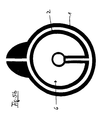
- FIG. 1 shows a schematic design for an integrating arrangement according to the invention of a tank resonant circuit 1 with an rf-SQUID 2.
- the characteristic parameters of the tank circuit 1 are essentially determined by the outer diameter D, to a lesser extent by the distance b of the capacitor C.
- the inductance increases. 1 2nd 3rd 4th 5 6 f o / 480 511.2 500 550 520 800 MHz Q o 2400 5900 6300 5500 4000 3500
- rf-SQUID 2 For simple analysis of the coupling between rf-SQUID 2 and Tank resonant circuit 1 becomes the working arrangement for a bulk rf SQUID examined (Fig. 2).
- a superconducting bulk cylinder becomes one Vulnerability (weak link) trained.
- This creates an rf-SQUID 2 with a remainder of the cylinder SQUID-loop 3, which with the help of a wound tank circuit coil 1a, which is inserted in the SQUID loop becomes.
- the material of the tank circuit coil 1 usually consists made of copper.
- the arrangement of the bulk rf SQUID 2 looks similar to that of the inventive design from FIG. 1.
- the arrangement from FIG. 1 differs from that from FIG. 2 or FIG. 3 in that that the tank circuit coil la encloses the rf-SQUID 2 (see also Fig. 4).
- the value k 2 is obtained for the coupling, which results from the ratio of the effective areas S e of the SQUID loop 3 and the area S c of the tank circuit coil 1 a.
- k 2nd S e / S c ⁇ ⁇ • R 2nd • R 3rd / ( ⁇ • R 1 2nd ) ⁇ ⁇ • R 3rd / R 1
- the integrated arrangement according to the invention enables many different SQUID structures to be used. This includes the washer SQUID structures and multiloop structures 5 according to Drung (FIG. 5a) already described.
- current injection SQUID structures 6 can be implemented using the single-layer technique (FIG. 5b).
- FIG. 5c single-layer
- FIG. 5d multi-layer transformers 7 with several turns instead of the washer structure
- the capacitive area of the resonant circuit 1 is also capacitively to a 50 ohm line (not shown) for Electronics that are at room temperature are coupled.
- rf-SQUID magnetometer 2 with planar resonant circuits and ⁇ / 2-or ⁇ resonators require a base plate 10 made of metal or superconductor material.
- the Tank resonant circuit 1 with integrated SQUID 2 and the base plate 10 can not be arranged in one plane.
- the base plate 10 provides a possible source of noise represents the use of an rf-SQUID magnetometer 2 can restrict.
- FIG. 6 shows a basic representation of an rf-SQUID 2 with a planar tank circuit 1 and a base plate 10.
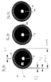
- FIGS. 7a, 7b and 7c each show a different geometry of a SQUID magnetometer 2, which is present as an RF resonant circuit in the arrangement with a coplanar outer loop 10a.
- Another external superconducting loop 10a is added to the SQUID geometry in FIG. 6.
- This loop 10a with a slot 11 represents the coplanar resonant circuit.
- the area A in FIG. 2a can be designed as a washer, multiloop or current injection SQUID structure.
- this surface is also possible to use this surface as a flux concentrator or flux transformer in order to combine the coplanar resonant circuit with a washer SQUID magnetometer in flip-chip geometry. Test measurements with this layout showed a quality of approx. 5000 and a white noise of 1.85 * 10 -5 ⁇ o / at a resonance frequency of the tank resonant circuit of 850 MHz. Hz (Fig. 8).
- FIGS. 7a to 7c A great advantage of these coplanar resonant circuits 10a is the geometry-dependent resonance frequency of the resonant circuit.
- Three different geometries are shown in FIGS. 7a to 7c. The only difference in these three representations is the orientation of slot 11 in the outer loop to slot 4 in the inner loop. In Fig. 7a both slots 4, 11 are aligned one above the other, the difference in orientation is 0 degrees.
Landscapes
- Physics & Mathematics (AREA)
- Condensed Matter Physics & Semiconductors (AREA)
- General Physics & Mathematics (AREA)
- Superconductor Devices And Manufacturing Methods Thereof (AREA)
- Measuring Magnetic Variables (AREA)
Description
- Fig. 1
- eine schematische Draufsicht eines rf-SQUID und eines Tankschwingkreises in der erfindungsgemäßen Anordnung;
- Fig. 2
- eine schematische, perspektivische Ansicht eines bulk-rf-SQUID mit innenliegendem Tankschwingkreis gemäß einer Anordnung des Standes der Technik;
- Fig. 3
- eine schematische Draufsicht des bulk-rf-SQUID aus Fig.2;
- Fig. 4
- eine schematische Draufsicht einer weiteren Ausführungsform des rf-SQUID aus Fig. 1 mit weiteren Abmessungsangaben;
- Fig. 5a
- eine schematische Draufsicht einer weiteren Ausfühzrungsform mit multiloop-SQUID-Struktur;
- Fig. 5b
- eine schematische Draufsicht einer weiteren Ausführungsform mit Strominjektion-SQUID-Struktur;
- Fig. 5c
- eine schematische Draufsicht einer weiteren Ausführungsform mit einlagigem Transformator;
- Fig. 5d
- eine schematische Draufsicht einer weiteren Ausführungsform mit mehrlagigem Transformator mit mehreren Windungen;
- Fig. 5e
- eine schematische Draufsicht einer weiteren Ausführungsform mit Doppelspulen-Gradiometer;
- Fig. 6
- eine Prinzipdarstellung eines rf-SQUID mit einem planaren Tankschwingkreis und einer Grundplatte gemäß den vorstehenden Ausführungsformen;
- Fig. 7a
- eine schematische Ansicht einer ersten Geometrie eines SQUID-Magnetometers mit einer als koplanare Schleife ausgebildeten Grundplatte;
- Fig. 7b
- eine schematische Ansicht einer zweiten Geometrie eines SQUID-Magnetometers mit einer als koplanare Schleife ausgebildeten Grundplatte;
- Fig. 7c
- eine schematische Ansicht einer dritten Geometrie eines SQUID-Magnetometers mit einer als koplanare Schleife ausgebildeten Grundplatte;
- Fig. 8
- ein Diagramm einer Testmessung mit einer Geometrie gemäß Fig. 7a.
a = 0.2 mm, b = 0.5 mm, D = 22 mm, Δ = 0.15 mm, s= 0.1 mm.
| 1 | 2 | 3 | 4 | 5 | 6 | |
| fo | / 480 | 511.2 | 500 | 550 | 520 | 800 |
| MHz | ||||||
| Qo | 2400 | 5900 | 6300 | 5500 | 4000 | 3500 |
Claims (13)
- Anordnung zur Ankopplung eines rf-SQUID-Magnetometers (2) an einen supraleitenden Tankschwingkreis (1),
dadurch gekennzeichnet,
daß der Tankschwingkreis (1) und das rf-SQUID-Magnetometer (2) auf den gleichen Substrat planar zueinander untergebracht sind, wobei der Tankschwingkreis (1) eine Schwingkreisspule (1a) und eine flächige kapazitive Struktur aufweist, die den rf-SQUID-Magnetometer (2) umschließen. - Anordnung nach Anspruch 1,
dadurch gekennzeichnet,
daß der Tankschwingkreis (1) aus supraleitendem Dünnschicht-Material besteht. - Anordnung nach Anspruch 1 oder 2,
dadurch gekennzeichnet,
daß das rf-SQUID-Magnetometer (2) einen rf-SQUID mit washer beinhaltet. - Anordnung nach einem der Ansprüche 1-3,
dadurch gekennzeichnet,
daß das rf-SQUID-Magnetometer (2) einen rf-SQUID mit multiloop-Struktur aufweist. - Anordnung nach einem der Ansprüche 1-3,
dadurch gekennzeichnet,
daß das rf-SQUID-Magnetometer (2) einen rf-SQUID mit Strominjektionsstruktur (6) beinhaltet. - Anordnung nach einem der Ansprüche 1-3,
dadurch gekennzeichnet,
daß das rf-SQUID-Magnetometer (2) einen rf-SQUID mit einlagiger oder mehrlagiger, mehrwindiger Transformatorstruktur (7) beinhaltet. - Anordnung nach einem der Ansprüche 1-3,
dadurch gekennzeichnet,
daß das rf-SQUID-Magnetometer (2) einen rf-SQUID mit Doppellochgradiometerstruktur mit gegensinnigen Spulen (9) aufweist. - Anordnung nach einem der vorstehenden Ansprüche,
dadurch gekennzeichnet,
daß der Schwingkreis (1) eine minimale Resonanzfrequenz von 400 MHz und eine minimale Güte von 1000 aufweist. - Anordnung nach einem der Ansprüche 1 bis 8,
dadurch gekennzeichnet,
daß das rf-SQUID-Magnetometer (2) an eine Grundplatte (10) angekoppelt ist. - Anordnung nach Anspruch 9,
dadurch gekennzeichnet,
daß die Schwingkreisspule (1a) als innere Schleife ausgebildet ist, die das rf-SQUID-Magnetometer (2) umschließt und einen Schlitz (4) aufweist. - Anordnung nach Anspruch 9 oder 10,
dadurch gekennzeichnet,
daß die Grundplatte (10) als äußere Schleife (10a) koplanar zu dem rf-SQUID-Magnetometer (2) und dem Tankschwingkreis (1) ausgebildet ist und einen Schlitz (11) aufweist. - Anordnung nach Anspruch 11,
dadurch gekennzeichnet,
daß die Orientierung der Schlitze (4; 11) der inneren Schleife (1a) und der äußeren Schleife (11) zueinander die Resonanzfrequenz fr bestimmt. - Anordnung nach Anspruch 12,
dadurch gekennzeichnet,
daß eine Verstellung der Schlitze (4; 11) eine Anderung der Resonanzfrequenz fr von < = 300 MHz bewirkt.
Applications Claiming Priority (5)
| Application Number | Priority Date | Filing Date | Title |
|---|---|---|---|
| DE19611900A DE19611900C2 (de) | 1996-03-26 | 1996-03-26 | Anordnung zur Ankopplung eines rf-SQUID-Magnetometers an einen supraleitenden Tankschwingkreis auf einem Substrat |
| DE19611900 | 1996-03-26 | ||
| DE29620718U DE29620718U1 (de) | 1996-03-26 | 1996-11-28 | Anordnung zur Ankopplung eines rf-SQUID-Magnetometers an einen supraleitenden Tankschwingkreis |
| DE29620718U | 1996-11-28 | ||
| PCT/DE1997/000552 WO1997036186A2 (de) | 1996-03-26 | 1997-03-18 | ANORDNUNG ZUR ANKOPPLUNG EINES rf-SQUID-MAGNETOMETERS AN EINEN SUPRALEITENDEN TANKSCHWINGKREIS |
Publications (2)
| Publication Number | Publication Date |
|---|---|
| EP0890113A2 EP0890113A2 (de) | 1999-01-13 |
| EP0890113B1 true EP0890113B1 (de) | 1999-10-06 |
Family
ID=26024136
Family Applications (1)
| Application Number | Title | Priority Date | Filing Date |
|---|---|---|---|
| EP97918034A Expired - Lifetime EP0890113B1 (de) | 1996-03-26 | 1997-03-18 | Anordnung zur ankopplung eines hf-squid-magnetometers an einen supraleitenden tankschwingkreis |
Country Status (5)
| Country | Link |
|---|---|
| US (1) | US6225800B1 (de) |
| EP (1) | EP0890113B1 (de) |
| JP (1) | JP2000507351A (de) |
| DE (1) | DE59700534D1 (de) |
| WO (1) | WO1997036186A2 (de) |
Families Citing this family (8)
| Publication number | Priority date | Publication date | Assignee | Title |
|---|---|---|---|---|
| US7002174B2 (en) * | 2001-12-18 | 2006-02-21 | D-Wave Systems, Inc. | Characterization and measurement of superconducting structures |
| US6784451B2 (en) * | 2001-12-18 | 2004-08-31 | D-Wave Systems Inc. | Multi-junction phase qubit |
| KR101136889B1 (ko) | 2005-07-12 | 2012-04-20 | 메사추세츠 인스티튜트 오브 테크놀로지 | 무선 비-방사성 에너지 전달 |
| US7825543B2 (en) | 2005-07-12 | 2010-11-02 | Massachusetts Institute Of Technology | Wireless energy transfer |
| DE102006006487A1 (de) * | 2006-02-10 | 2007-08-23 | Forschungszentrum Jülich GmbH | Anordnung zur Messung magnetischer Signale |
| US8179133B1 (en) | 2008-08-18 | 2012-05-15 | Hypres, Inc. | High linearity superconducting radio frequency magnetic field detector |
| EP2345100B1 (de) | 2008-10-01 | 2018-12-05 | Massachusetts Institute of Technology | Effiziente nahfeld-drahtlosenergieübertragung anhand adiabatischer systemveränderungen |
| US8970217B1 (en) | 2010-04-14 | 2015-03-03 | Hypres, Inc. | System and method for noise reduction in magnetic resonance imaging |
Family Cites Families (6)
| Publication number | Priority date | Publication date | Assignee | Title |
|---|---|---|---|---|
| DE3769201D1 (de) | 1986-05-21 | 1991-05-16 | Siemens Ag | Squid-magnetometer fuer eine vorrichtung zur messung schwacher magnetfelder. |
| DE4003524A1 (de) | 1990-02-06 | 1991-08-08 | Forschungszentrum Juelich Gmbh | Schaltungsanordnung mit supraleitenden quanten interferenz detektoren (squid) |
| US5326986A (en) | 1991-03-05 | 1994-07-05 | University Of Houston - University Park | Parallel N-junction superconducting interferometer with enhanced flux-to-voltage transfer function |
| JPH05297089A (ja) | 1992-04-20 | 1993-11-12 | Sumitomo Electric Ind Ltd | 磁気センサ |
| DE4433331C2 (de) | 1994-09-19 | 2002-06-20 | Siemens Ag | Magnetfeldempfindliche SQUID-Sensoreinrichtung mit Flußtransformator unter Verwendung von Hoch-T¶c¶-Supraleitermaterial |
| DE4436448C1 (de) | 1994-10-13 | 1996-02-29 | Forschungszentrum Juelich Gmbh | SQUID mit supraleitender Schleife und Resonator |
-
1997
- 1997-03-18 EP EP97918034A patent/EP0890113B1/de not_active Expired - Lifetime
- 1997-03-18 WO PCT/DE1997/000552 patent/WO1997036186A2/de not_active Ceased
- 1997-03-18 DE DE59700534T patent/DE59700534D1/de not_active Expired - Fee Related
- 1997-03-18 JP JP9533932A patent/JP2000507351A/ja active Pending
- 1997-03-18 US US09/155,342 patent/US6225800B1/en not_active Expired - Fee Related
Also Published As
| Publication number | Publication date |
|---|---|
| DE59700534D1 (de) | 1999-11-11 |
| WO1997036186A3 (de) | 1997-11-20 |
| WO1997036186A2 (de) | 1997-10-02 |
| US6225800B1 (en) | 2001-05-01 |
| EP0890113A2 (de) | 1999-01-13 |
| JP2000507351A (ja) | 2000-06-13 |
Similar Documents
| Publication | Publication Date | Title |
|---|---|---|
| DE69101788T2 (de) | Hochsymmetrischer gleichstrom-squid. | |
| EP0895092B1 (de) | Supraleitender Hybrid-Resonator für dem Empfang von NMR-Signalen | |
| DE69615180T2 (de) | Sondenspule für die kernspinresonanz | |
| EP0111827B1 (de) | Vorrichtung zur mehrkanaligen Messung schwacher, sich ändernder Magnetfelder und Verfahren zu ihrer Herstellung | |
| EP0200080B1 (de) | Vorrichtung zur Messung schwacher Magnetfelder mit wenigstens einem DC-SQUID | |
| EP1251361A2 (de) | Supraleitende Resonatoren für Anwendungen in der NMR | |
| DE69623160T2 (de) | Dielektrischer Resonator und dielektrische Resonatorvorrichtung damit | |
| DE4204369C2 (de) | Verfahren zur Qualitätsbestimmung eines einzelnen supraleitenden Filmes und Vorrichtung zur Durchführung dieses Verfahrens | |
| EP0246419A1 (de) | SQUID-Magnetometer für eine Vorrichtung zur Messung schwacher Magnetfelder | |
| DE4218635C2 (de) | Hochfrequenz-Empfangsantenne einer Einrichtung zur Kernspintomographie mit mindestens einem Kondensator | |
| EP0890113A2 (de) | ANORDNUNG ZUR ANKOPPLUNG EINES rf-SQUID-MAGNETOMETERS AN EINEN SUPRALEITENDEN TANKSCHWINGKREIS | |
| WO1998023969A2 (de) | ANORDNUNG ZUR ANKOPPLUNG EINES rf-SQUID AN EINEN SUPRALEITENDEN TANKSCHWINGKREIS | |
| EP0799425B1 (de) | Gradiometer | |
| DE19611900C2 (de) | Anordnung zur Ankopplung eines rf-SQUID-Magnetometers an einen supraleitenden Tankschwingkreis auf einem Substrat | |
| DE19927661B4 (de) | Anordnung aus Träger und supraleitendem Film | |
| DE102015206788B3 (de) | NMR Sende/Empfangsspulenanordnung | |
| DE4333182A1 (de) | Doppeltresonante Antennenanordnung für ein Magnetresonanzgerät | |
| DE19717801C2 (de) | Anordnung zur Ankopplung eines rf-Squid an einen supraleitenden Tankschwingkreis | |
| DE19816218A1 (de) | SQUID-Sensor mit geringer SQUID-Induktivität und starker magnetischer Kopplung mit einer integrierten Einkoppelspule mit großer Induktivität | |
| DE19639941C2 (de) | SQUID-Gradienten-Magnetometer-Sensor mit HTS-Supraleitermaterial | |
| EP0787362B1 (de) | Konzentriertes bauelement und ein solches enthaltende hochfrequenzschaltung | |
| EP1358501B1 (de) | Rf-squid magnetometer | |
| DE112018005423T5 (de) | Magnetfeld-messelement, magnetfeld-messvorrichtung und magnetfeld-messsystem | |
| DE10111619C1 (de) | Planares Layout für die Operation eines rf-SQUID-Magnetometers | |
| DE19517399A1 (de) | rf-SQUID mit Resonator |
Legal Events
| Date | Code | Title | Description |
|---|---|---|---|
| PUAI | Public reference made under article 153(3) epc to a published international application that has entered the european phase |
Free format text: ORIGINAL CODE: 0009012 |
|
| AK | Designated contracting states |
Kind code of ref document: A2 Designated state(s): DE FR GB IT |
|
| 17P | Request for examination filed |
Effective date: 19980922 |
|
| GRAG | Despatch of communication of intention to grant |
Free format text: ORIGINAL CODE: EPIDOS AGRA |
|
| GRAG | Despatch of communication of intention to grant |
Free format text: ORIGINAL CODE: EPIDOS AGRA |
|
| GRAH | Despatch of communication of intention to grant a patent |
Free format text: ORIGINAL CODE: EPIDOS IGRA |
|
| 17Q | First examination report despatched |
Effective date: 19990324 |
|
| GRAH | Despatch of communication of intention to grant a patent |
Free format text: ORIGINAL CODE: EPIDOS IGRA |
|
| GRAA | (expected) grant |
Free format text: ORIGINAL CODE: 0009210 |
|
| AK | Designated contracting states |
Kind code of ref document: B1 Designated state(s): DE FR GB IT |
|
| REF | Corresponds to: |
Ref document number: 59700534 Country of ref document: DE Date of ref document: 19991111 |
|
| ITF | It: translation for a ep patent filed | ||
| GBT | Gb: translation of ep patent filed (gb section 77(6)(a)/1977) |
Effective date: 19991129 |
|
| ET | Fr: translation filed | ||
| PLBE | No opposition filed within time limit |
Free format text: ORIGINAL CODE: 0009261 |
|
| STAA | Information on the status of an ep patent application or granted ep patent |
Free format text: STATUS: NO OPPOSITION FILED WITHIN TIME LIMIT |
|
| 26N | No opposition filed | ||
| PG25 | Lapsed in a contracting state [announced via postgrant information from national office to epo] |
Ref country code: FR Free format text: LAPSE BECAUSE OF NON-PAYMENT OF DUE FEES Effective date: 20010531 |
|
| REG | Reference to a national code |
Ref country code: FR Ref legal event code: ST |
|
| REG | Reference to a national code |
Ref country code: FR Ref legal event code: RN |
|
| REG | Reference to a national code |
Ref country code: FR Ref legal event code: FC |
|
| REG | Reference to a national code |
Ref country code: GB Ref legal event code: IF02 |
|
| PGFP | Annual fee paid to national office [announced via postgrant information from national office to epo] |
Ref country code: GB Payment date: 20050307 Year of fee payment: 9 |
|
| PGFP | Annual fee paid to national office [announced via postgrant information from national office to epo] |
Ref country code: DE Payment date: 20050309 Year of fee payment: 9 |
|
| PGFP | Annual fee paid to national office [announced via postgrant information from national office to epo] |
Ref country code: FR Payment date: 20050318 Year of fee payment: 9 |
|
| PG25 | Lapsed in a contracting state [announced via postgrant information from national office to epo] |
Ref country code: GB Free format text: LAPSE BECAUSE OF NON-PAYMENT OF DUE FEES Effective date: 20060318 |
|
| PGFP | Annual fee paid to national office [announced via postgrant information from national office to epo] |
Ref country code: IT Payment date: 20060331 Year of fee payment: 10 |
|
| PG25 | Lapsed in a contracting state [announced via postgrant information from national office to epo] |
Ref country code: DE Free format text: LAPSE BECAUSE OF NON-PAYMENT OF DUE FEES Effective date: 20061003 |
|
| GBPC | Gb: european patent ceased through non-payment of renewal fee |
Effective date: 20060318 |
|
| PG25 | Lapsed in a contracting state [announced via postgrant information from national office to epo] |
Ref country code: IT Free format text: LAPSE BECAUSE OF NON-PAYMENT OF DUE FEES Effective date: 20070318 |