EP0888951A2 - Sensor installation structure for vehicles - Google Patents
Sensor installation structure for vehicles Download PDFInfo
- Publication number
- EP0888951A2 EP0888951A2 EP98112175A EP98112175A EP0888951A2 EP 0888951 A2 EP0888951 A2 EP 0888951A2 EP 98112175 A EP98112175 A EP 98112175A EP 98112175 A EP98112175 A EP 98112175A EP 0888951 A2 EP0888951 A2 EP 0888951A2
- Authority
- EP
- European Patent Office
- Prior art keywords
- cover
- sensor
- sealing material
- housing structure
- potentiometer
- Prior art date
- Legal status (The legal status is an assumption and is not a legal conclusion. Google has not performed a legal analysis and makes no representation as to the accuracy of the status listed.)
- Granted
Links
Images


Classifications
-
- B—PERFORMING OPERATIONS; TRANSPORTING
- B66—HOISTING; LIFTING; HAULING
- B66F—HOISTING, LIFTING, HAULING OR PUSHING, NOT OTHERWISE PROVIDED FOR, e.g. DEVICES WHICH APPLY A LIFTING OR PUSHING FORCE DIRECTLY TO THE SURFACE OF A LOAD
- B66F9/00—Devices for lifting or lowering bulky or heavy goods for loading or unloading purposes
- B66F9/06—Devices for lifting or lowering bulky or heavy goods for loading or unloading purposes movable, with their loads, on wheels or the like, e.g. fork-lift trucks
- B66F9/075—Constructional features or details
-
- B—PERFORMING OPERATIONS; TRANSPORTING
- B62—LAND VEHICLES FOR TRAVELLING OTHERWISE THAN ON RAILS
- B62D—MOTOR VEHICLES; TRAILERS
- B62D15/00—Steering not otherwise provided for
- B62D15/02—Steering position indicators ; Steering position determination; Steering aids
- B62D15/021—Determination of steering angle
- B62D15/023—Determination of steering angle by measuring on the king pin
-
- B—PERFORMING OPERATIONS; TRANSPORTING
- B62—LAND VEHICLES FOR TRAVELLING OTHERWISE THAN ON RAILS
- B62D—MOTOR VEHICLES; TRAILERS
- B62D7/00—Steering linkage; Stub axles or their mountings
- B62D7/18—Steering knuckles; King pins
Definitions
- the present invention relates to a sensor installation structure for industrial vehicles.
- the swing amount of the rear axle is restrained by a controller to prevent the excessive inclination of the vehicles due to centrifugal force when turning.
- the control is executed based on the centrifugal acceleration and the yaw rate that act on the vehicles.
- the centrifugal acceleration is calculated from the steering angle (or wheel angle) of the wheels and the speed of the vehicles.
- a method to calculate the wheel angle is described in Japanese Examined Patent Publication No. 4-24270.
- the forklift described in that publication has a power steering apparatus.
- the power steering apparatus includes a steering shaft rotated by a steering wheel and a valve unit connected to the shaft.
- the valve unit supplies hydraulic oil to and drains the oil from a cylinder in accordance with the rotation of the steering shaft.
- Piston rods protrude from both ends of the cylinder, and each piston rod is connected to a wheel.
- the cylinder is driven by hydraulic oil from the valve unit to steer the wheels.
- the piston rod motion is detected by a stroke sensor, and the wheel angle is calculated based on the detected value.
- the linear movement of the piston rods have to be converted to the wheel angle, and the piston rod movement is not proportional to the wheel angle. This is because the piston rod linear movement is converted to the wheel rotation movement via a transmission mechanism such as a link. Accordingly, determining the wheel angle with respect to the piston rod movement is not easy.
- the wheel angle may be directly detected using a potentiometer.
- the potentiometer detects the rotation angle of a kingpin rotated with the wheels.
- the kingpin is pivotally supported by an upper bracket that constitutes an axle beam.
- the potentiometer is provided on the upper bracket, that is, over the kingpin, to detect the kingpin rotation angle.
- the potentiometer since the upper bracket is located in a wheel well, the potentiometer is also located in the wheel well. Accordingly, the potentiometer is exposed to foreign substances such as pebbles and water spattered by the wheels. To protect the potentiometer from such foreign matter, the potentiometer is covered by a case made of hard material such as metal. The case has an opening for passage of the lead wires connected to the potentiometer.
- the objective of the present invention is to provide a sensor installation structure to ensure the protection of the sensor.
- the present invention provides a housing structure for protecting a vehicle sensor, wherein the sensor is provided on a structural member that is exposed to the environment, and wherein lead wires are connected to the sensor.
- the housing structure includes a cover fixed on the member to cover the sensor, wherein, the cover has an opening for permitting the passage of the lead wires, and a sealing material located between the cover and the sensor to seal the sensor.
- the present invention further provides a cover for covering a sensor installed on a vehicle structural member, wherein the structural member is exposed to the environment, and wherein the cover has an opening for permitting the passage of lead wires of the sensor and a through hole, which is formed in a wall of the cover, for facilitating a sealing process for sealing the sensor.
- the present invention also provides a method for installing a sensor in a vehicle, wherein lead wires are attached to the sensor.
- the method includes fixing the sensor on a structural member of the vehicle, covering the sensor with a cover, wherein the cover is exposed to the environment, and wherein the lead wires pass through an opening in the cover, charging a fluid sealing material inside the cover through the cover opening, and hardening the charged sealing material.
- a drive train of rear wheels 2 includes a rear axle beam 1 for supporting the rear wheels 2, steering rods 5, 6 for steering the rear wheels 2, a cylinder 31 for moving a rod 32 axially by manipulating a steering wheel (not shown), and a bell crank 3 for converting the linear movement of the rod 32 to rotation movement of the rear wheels.
- the bell crank 3 is pivotally supported on the rear axle beam 1 with a bell crank pin 4.
- the bell crank 3 is connected to steering knuckles 7, 8 by way of steering rods 5, 6.
- the knuckles 7, 8 support the rear wheels 2 on both sides of the rear axle beam 1.
- a first end of the steering rod 5 is pivotally connected to the bell crank 3 with a pin 9a, and a second end is connected to the steering knuckle 7 with a pin 10a.
- a first end of the steering rod 6 is pivotally connected to the bell crank 3 with a pin 9b, and a second end is connected to the steering knuckle 8 with a pin 10b.
- the rod 32 is connected to the bell crank 33 through a joint 33.
- Fig. 1 shows a sectional view of a rear axle beam 1.
- the rear axle beam 1 includes an upper member 11 and a lower member 13.
- An upper bracket 12 is rigidly attached to the upper member 11, and a lower bracket 14 to the lower member 13.
- the upper bracket 12 and the lower bracket 14 support pivotally a kingpin 15 by way of a pair of needle bearings 16.
- the steering knuckle 7 is fixed on the kingpin 15 to rotate integrally.
- the steering knuckle 7 has an axle 17.
- the rear wheels 2 are rotatably supported by the axle 17 through a pair of tapered roller bearings 18, 19.
- a sensor that is, a potentiometer 21, is provided on the upper side 12a of the upper bracket 12 by way of a plate 20.
- the potentiometer 21 is fixed to the plate 20 by a screw 22.
- the wheel 2 and the upper bracket 12 are covered with a wheel cover (not shown).
- the plate 20 has a through hole 20a.
- An input shaft 23 is connected to the kingpin 15 through the hole 20a.
- the potentiometer 21 detects the rotation angle of the kingpin 15, that is, the wheel 2, through the input shaft 23.
- the bell crank 3 is steered based on the rotation of the steering wheel
- the steering knuckles 7, 8 are steered through the steering rods 5, 6.
- the rear wheel 2 is steered by a wheel angle based on the steering wheel rotation amount.
- the kingpin 15 rotates according to the wheel angle and the input shaft 23 rotates the same amount as that of the kingpin 15.
- the potentiometer 21 detects the rotation amount of the kingpin 15, which corresponds to the wheel angle.
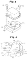
- a sensor cover 24 is attached on the plate 20 by way of a gasket 25 to cover the potentiometer 21.
- the sensor cover 24 is fixed on the upper bracket 12, together with the plate 20 by screws 26.
- the sensor cover 24 is formed of, for example, metal, in a shape to shelter the potentiometer 21. Materials other than metal such as synthetic resin and ceramics may also be used to form the sensor cover 24.
- the sensor cover 24 has an opening 24a for permitting passage of the lead wires 27 connected to the potentiometer 21.
- a sealing material 28 is charged between the sensor cover 24 and the potentiometer 21, to seal the potentiometer 21 from the environment.
- epoxy resin which is a thermosetting resin, is employed as the sealing material 28.
- the sealing material 28 which is in a fluid state, is injected inside the sensor cover 24 through the opening 24a.
- the opening 24a should be temporarily covered with a lid (not shown), which may be either left in place or taken off after the resin hardens.
- the sealing material 28 is then heated from outside the sensor cover 24 and is hardened.
- temperatures higher than 100°C are avoided during heating.
- the condition for hardening resins differ according to the kind of resin, and there is one type that hardens at normal temperatures.
- the potentiometer 21 is doubly sealed by the sensor cover 24 and the sealing material 28. As a result, the potentiometer 21 is protected from pebbles, dust, and rain water, thus avoiding degradation of its detection accuracy and durability.
- the potentiometer 21 is sealed after the assembly of the potentiometer 21 with lead wires connected and the sensor cover 24 in place.
- a sensor installation structure and method for a potentiometer (21) located on the exterior of a fork lift A sensor cover (24) is fixed to a bracket (12) to Protect the potentiometer (21).
- the cover (24) has an opening (24a, 30) permitting the passage of lead wires (27).
- a fluid sealant is charged between the cover (24) and the potentiometer (21) to seal the potentiometer (21).
Abstract
Description
Claims (15)
- A housing structure for protecting a vehicle sensor, wehrein the sensor is provided on a structural member (12), that is exposed to the environment, and wherein lead wires (27) are connected to the sensor (21), the housing structure comprising:a cover (24) fixed on the member (12) to cover the sensor (21), wherein, the cover (24) has an opening (24a; 30) for permitting the passage of the lead wires (27); the structure being characterized by:a sealing material (28) located between the cover (24) and the sensor (21) to seal the sensor (21).
- The sensor housing structure according to claim 1 characterized in that the sealing material (28) is a substantially solid hardened substance that was charged into the cover (24) when in a liquid state.
- The sensor housing structure according to claim 2 characterized in that the opening (30) is located on an upper side of the cover (24).
- The sensor housing structure according to claim 1 characterized in that the cover (24) further has a through hole (29) formed through a wall of the cover (24).
- The sensor housing structure according to claim 4 characterized in that the sealing material (28) is a substantially solid hardened substance that is charged inside the cover (24) when in a liquid state through the through hole (29).
- The sensor housing structure according to claim 4 characterized in that the sealing material (28) is a substantially solid hardened substance that is charged inside the cover (24) when in a liquid state through the opening (24a; 30), and wherein the through hole (29) serves to discharge air from inside the cover (24) during the charging of the sealing material (28).
- The sensor housing structure according to claim 4 characterized in that the through hole (29) is located on the upper side of the cover (24).
- The sensor housing structure according to claim 1 characterized in that the vehicle is a fork lift, the sensor is a potentiometer (21) installed on a kingpin (15) rotated integrally with a steered wheel (2), and the structural member is a bracket (12) supporting the kingpin (15).
- The sensor housing structure according to claim 1 characterized in that a gasket (25) is located between the cover (24) and the structural member (12).
- A cover (24) for covering a sensor (21) installed on a vehicle structural member (12), wherein the structural member is exposed to the environment, the cover (24) being characterized by:an opening (24a; 30) formed in a wall of the cover (24) for permitting the passage of lead wires (27) of the sensor (21); anda through hole (29) formed in a wall of the cover (24a) for facilitating a sealing process for sealing the sensor (21).
- The cover according to claim 10 characterized in that the through hole (29) serves as an entry passage for charging a fluid sealing material (28) into the cover (24).
- The cover according to claim 10 characterized in that the through hole (29) serves as an exit passage for discharging air displaced by a liquid sealant (28) during the sealing process.
- A method for installing a sensor (21) in a vehicle, wherein lead wires (27) are attached to the sensor (21), the method being characterized by the steps of:fixing the sensor (21) on a structural member (12) of the vehicle;covering the sensor (21) with a cover (24), wherein the cover (24) is exposed to the environment, and wherein the lead wires (27) pass through an opening (24a; 30) in the cover (24);charging a fluid sealing material (28) inside the cover (24) through the cover opening (24a; 30); andhardening the charged sealing material (28).
- The sensor installation method according to claim 13 characterized by discharging air from inside the cover (24) through a through hole (29) during the step of charging the sealing material.
- The sensor installation method according to claim 14 characterized by placing a gasket (25) between the cover (24) and the structural member (12).
Applications Claiming Priority (3)
| Application Number | Priority Date | Filing Date | Title |
|---|---|---|---|
| JP17714597 | 1997-07-02 | ||
| JP177145/97 | 1997-07-02 | ||
| JP9177145A JPH1120729A (en) | 1997-07-02 | 1997-07-02 | Sensor mounting structure for vehicle |
Publications (3)
| Publication Number | Publication Date |
|---|---|
| EP0888951A2 true EP0888951A2 (en) | 1999-01-07 |
| EP0888951A3 EP0888951A3 (en) | 2001-01-10 |
| EP0888951B1 EP0888951B1 (en) | 2002-11-06 |
Family
ID=16025984
Family Applications (1)
| Application Number | Title | Priority Date | Filing Date |
|---|---|---|---|
| EP98112175A Expired - Lifetime EP0888951B1 (en) | 1997-07-02 | 1998-07-01 | Sensor installation structure for vehicles |
Country Status (9)
| Country | Link |
|---|---|
| US (1) | US6502839B1 (en) |
| EP (1) | EP0888951B1 (en) |
| JP (1) | JPH1120729A (en) |
| KR (1) | KR100276040B1 (en) |
| CN (1) | CN1137513C (en) |
| AU (1) | AU702712B2 (en) |
| CA (1) | CA2242021C (en) |
| DE (1) | DE69809136T2 (en) |
| TW (1) | TW400305B (en) |
Cited By (6)
| Publication number | Priority date | Publication date | Assignee | Title |
|---|---|---|---|---|
| FR2783791A1 (en) * | 1998-09-30 | 2000-03-31 | Dana Corp | FOAM INSERT STEERING MECHANISM |
| WO2001081235A1 (en) * | 2000-04-21 | 2001-11-01 | Cesab Carrelli Elevatori S.P.A. | A forklift truck with reduced turning radius |
| WO2002046025A3 (en) * | 2000-12-08 | 2002-09-26 | Clark Equipment Co | Kingpin angle mounted sensor |
| EP1348668A1 (en) * | 2002-03-29 | 2003-10-01 | Manitou Bf | Variable reach lift truck with three wheels |
| EP1726512A1 (en) | 2005-05-28 | 2006-11-29 | AGCO GmbH | Steering angle sensor on a ball joint of a vehicle single wheel suspension |
| CN108802709A (en) * | 2017-05-04 | 2018-11-13 | 法拉第未来公司 | Modified lidar housings |
Families Citing this family (24)
| Publication number | Priority date | Publication date | Assignee | Title |
|---|---|---|---|---|
| DE10023196C2 (en) * | 2000-05-11 | 2003-04-03 | Orenstein & Koppel Ag | Device for detecting the angle of rotation between two components |
| NL1018697C2 (en) * | 2001-08-03 | 2003-02-04 | Skf Ab | Suspension module for a vehicle and assembly comprising such a module. |
| US6928728B2 (en) * | 2002-08-08 | 2005-08-16 | Badger Meter, Inc. | Meter register with water vapor seal |
| US7093843B2 (en) * | 2003-05-14 | 2006-08-22 | Arvinmeritor Technology Llc | King pin arrangement for steering knuckle |
| US7574926B2 (en) * | 2003-12-19 | 2009-08-18 | Deere & Company | Rotary cam driven sensor and feedback control |
| US7296810B2 (en) * | 2004-04-01 | 2007-11-20 | Cnh America Llc | Apparatus and method for installing a sensor in connection with relatively movable members for sensing relative position thereof without adjustment |
| US7543831B2 (en) * | 2004-09-01 | 2009-06-09 | Cnh America Llc | Apparatus for installing a sensor on a kingpin |
| DE102004053690A1 (en) * | 2004-11-06 | 2006-05-11 | Zf Lenksysteme Gmbh | Method and device for determining a steering angle of a vehicle |
| JP4819455B2 (en) * | 2005-09-15 | 2011-11-24 | 川崎重工業株式会社 | VEHICLE ROTATION DETECTION DEVICE AND MOTORCYCLE WITH THE SAME |
| JP4775675B2 (en) * | 2009-07-28 | 2011-09-21 | 株式会社デンソー | Range detector |
| KR101239331B1 (en) * | 2011-08-25 | 2013-03-05 | 정휘동 | Sensor mounting structure for water purifier and hot and cold water dispenser |
| US10358165B2 (en) * | 2015-08-05 | 2019-07-23 | Dennis Reid | Kingpin unit bearing steerable drive axle assembly |
| US10527464B2 (en) | 2016-08-18 | 2020-01-07 | Ford Global Technologies, Llc | Rotatable sensor cover |
| USD809995S1 (en) * | 2016-08-18 | 2018-02-13 | Ford Motor Company | Sensor cover |
| USD797646S1 (en) | 2016-08-18 | 2017-09-19 | Ford Motor Company | Sensor cover |
| USD838231S1 (en) | 2016-08-18 | 2019-01-15 | Ford Motor Company | Sensor cover |
| USD838230S1 (en) | 2016-08-18 | 2019-01-15 | Ford Motor Company | Sensor cover |
| US10654522B2 (en) * | 2017-09-07 | 2020-05-19 | Uatc, Llc | System for actively monitoring the steering angle of a vehicle using a kingpin sensor |
| US11702155B2 (en) | 2018-01-19 | 2023-07-18 | Saf-Holland, Inc. | Kingpin assembly with rotation sensor arrangement |
| CN110667703A (en) * | 2019-10-11 | 2020-01-10 | 上海科曼车辆部件系统股份有限公司 | Independent suspension axle system for commercial vehicle |
| KR102244449B1 (en) * | 2019-12-09 | 2021-04-26 | 주식회사 지에스엠 | Sensor module structure for axle-mounted car celebration |
| WO2022162676A1 (en) * | 2021-02-01 | 2022-08-04 | Ree Automotive Ltd. | Apparatus for measuring steering angle |
| EP4243230A1 (en) * | 2022-03-07 | 2023-09-13 | Elettrosud Srl | Watertight wiring between cable and ffc |
| CN114919657B (en) * | 2022-06-14 | 2023-09-15 | 安庆合力车桥有限公司 | Floating steering axle rotation angle detection device |
Citations (1)
| Publication number | Priority date | Publication date | Assignee | Title |
|---|---|---|---|---|
| JPH0424270A (en) | 1990-05-21 | 1992-01-28 | Kanebo Ltd | Continuous cleaning device for cloth |
Family Cites Families (31)
| Publication number | Priority date | Publication date | Assignee | Title |
|---|---|---|---|---|
| US3599141A (en) * | 1969-07-07 | 1971-08-10 | Spectrol Electronics Corp | Variable resistor having means for sealing between a lead screw and the housing |
| JPS5816684B2 (en) | 1978-09-28 | 1983-04-01 | 日産自動車株式会社 | Ignition prevention structure for automobile instruments |
| US4498554A (en) * | 1982-05-03 | 1985-02-12 | Young Roy E | Highly maneuverable prime mover |
| FR2560428B1 (en) * | 1984-02-28 | 1987-02-27 | Renix Electronique Sa | ROTARY POTENTIOMETER IN PARTICULAR FOR ANGULAR POSITION MEASUREMENT |
| GB2167729B (en) * | 1984-11-27 | 1988-05-11 | Kubota Ltd | Load lifting vehicle |
| JPS61261164A (en) | 1985-05-13 | 1986-11-19 | Nissan Motor Co Ltd | Fully hydraulic type power steering device |
| US4847557A (en) * | 1987-03-18 | 1989-07-11 | Sumitomo Electric Industries, Ltd. | Hermetically sealed magnetic sensor |
| JPH07121220B2 (en) | 1988-07-18 | 1995-12-25 | 株式会社日立製作所 | Animal cell culture device, culture method and activity diagnostic device |
| IT219805Z2 (en) * | 1989-10-10 | 1993-05-17 | Same Spa | STEERING ANGLE MEASURING DEVICE FOR ELECTRICAL SYSTEMS AND CONTROL OF DIFFERENTIALS AND DOUBLE TRACTION OF A TRACTOR |
| US5052119A (en) * | 1989-12-27 | 1991-10-01 | North American Philips Corporation | Angular micro-positioning device |
| US5059940A (en) * | 1990-01-24 | 1991-10-22 | Bourns, Inc. | Single turn potentiometer with direct rotor-to-housing seal |
| GB2249869B (en) * | 1990-09-17 | 1994-10-12 | Fuji Electric Co Ltd | Semiconductor device |
| US5557142A (en) * | 1991-02-04 | 1996-09-17 | Motorola, Inc. | Shielded semiconductor device package |
| FR2674177B1 (en) * | 1991-03-20 | 1993-06-25 | Telemecanique | METHOD FOR WALKING IN RESIN THE INTERIOR OF AN ELECTRICAL APPARATUS SUCH AS A PROXIMITY DETECTOR, AND ELECTRICAL APPARATUS RELATING THERETO. |
| DE4134794A1 (en) * | 1991-10-22 | 1993-04-29 | Fichtel & Sachs Ag | SENSOR FOR AN ACTUATOR, ESPECIALLY IN A VEHICLE |
| JPH0661653A (en) | 1992-05-29 | 1994-03-04 | Nec Corp | Frame body structure for controller |
| JPH0662325A (en) | 1992-08-11 | 1994-03-04 | Toshiba Corp | Image pickup device using solid-state image pickup element |
| JP3238492B2 (en) * | 1992-10-19 | 2001-12-17 | 株式会社タイセー | Piezoelectric sensor |
| US5412159A (en) * | 1993-09-27 | 1995-05-02 | Zenith Electronics Corporation | High voltage resistive network circuit board with good potting adhesion |
| EP0703613A3 (en) * | 1994-09-26 | 1996-06-05 | Motorola Inc | Protecting electronic components in acidic and basic environments |
| US5750925A (en) * | 1994-10-05 | 1998-05-12 | Loral Fairchild Corp. | Flight crash survivable storage unit with boiler for flight recorder memory |
| JP3391123B2 (en) | 1994-11-30 | 2003-03-31 | 株式会社デンソー | Sensor device packaging method |
| US5629618A (en) * | 1994-12-27 | 1997-05-13 | Ssi Technologies, Inc. | Housing for a wheel speed sensor |
| EP0722200B1 (en) * | 1995-01-10 | 2001-03-21 | Sumitomo Wiring Systems, Ltd. | Junction box |
| US5636703A (en) * | 1995-06-12 | 1997-06-10 | Deere & Company | Rotary axle-mounted feedback transducer |
| EP1372266B1 (en) * | 1995-07-18 | 2005-02-23 | Omron Corporation | Electronic equipment and method of manufacturing the same |
| US5657544A (en) * | 1995-09-26 | 1997-08-19 | Ntn Corporation | Device for detecting the angle of rotation |
| DE59509980D1 (en) * | 1995-09-28 | 2002-02-07 | Endress Hauser Gmbh Co | electronics housing |
| US5734103A (en) * | 1996-09-13 | 1998-03-31 | Badger Meter, Inc. | Sealed wire entry for instrument housing and method of sealing |
| AU706372B2 (en) * | 1997-04-25 | 1999-06-17 | Kabushiki Kaisha Toyoda Jidoshokki Seisakusho | Mounting structure for wheel angle detector and rotation amount detector for vehicle wheel |
| CA2208121A1 (en) | 1997-06-18 | 1998-12-18 | Dick A. Wolters | Temperature sensors for bearings |
-
1997
- 1997-07-02 JP JP9177145A patent/JPH1120729A/en active Pending
-
1998
- 1998-06-29 TW TW087110448A patent/TW400305B/en not_active IP Right Cessation
- 1998-06-30 CN CNB981033741A patent/CN1137513C/en not_active Expired - Fee Related
- 1998-06-30 CA CA002242021A patent/CA2242021C/en not_active Expired - Fee Related
- 1998-07-01 EP EP98112175A patent/EP0888951B1/en not_active Expired - Lifetime
- 1998-07-01 KR KR1019980026346A patent/KR100276040B1/en not_active IP Right Cessation
- 1998-07-01 DE DE69809136T patent/DE69809136T2/en not_active Expired - Fee Related
- 1998-07-01 US US09/108,511 patent/US6502839B1/en not_active Expired - Fee Related
- 1998-07-01 AU AU73977/98A patent/AU702712B2/en not_active Ceased
Patent Citations (1)
| Publication number | Priority date | Publication date | Assignee | Title |
|---|---|---|---|---|
| JPH0424270A (en) | 1990-05-21 | 1992-01-28 | Kanebo Ltd | Continuous cleaning device for cloth |
Cited By (13)
| Publication number | Priority date | Publication date | Assignee | Title |
|---|---|---|---|---|
| FR2783791A1 (en) * | 1998-09-30 | 2000-03-31 | Dana Corp | FOAM INSERT STEERING MECHANISM |
| NL1013040C2 (en) * | 1998-09-30 | 2003-11-18 | Dana Corp | Steering mechanism. |
| WO2001081235A1 (en) * | 2000-04-21 | 2001-11-01 | Cesab Carrelli Elevatori S.P.A. | A forklift truck with reduced turning radius |
| US6568696B2 (en) | 2000-12-08 | 2003-05-27 | Clark Equipment Company | Kingpin angle mounted sensor |
| WO2002046025A3 (en) * | 2000-12-08 | 2002-09-26 | Clark Equipment Co | Kingpin angle mounted sensor |
| EP1348668A1 (en) * | 2002-03-29 | 2003-10-01 | Manitou Bf | Variable reach lift truck with three wheels |
| FR2837809A1 (en) * | 2002-03-29 | 2003-10-03 | Manitou Bf | LIFT TRUCK WITH VARIABLE RANGE WITH THREE WHEELS |
| US7121372B2 (en) | 2002-03-29 | 2006-10-17 | Manitou Bf | Lift truck with variable range with at least three wheels |
| EP1726512A1 (en) | 2005-05-28 | 2006-11-29 | AGCO GmbH | Steering angle sensor on a ball joint of a vehicle single wheel suspension |
| GB2426492A (en) * | 2005-05-28 | 2006-11-29 | Agco Gmbh | Vehicle with ball joint and wheel angle sensor assembly |
| US7413201B2 (en) | 2005-05-28 | 2008-08-19 | Agco Gmbh | Steering systems |
| GB2426492B (en) * | 2005-05-28 | 2009-01-07 | Agco Gmbh | Steering systems |
| CN108802709A (en) * | 2017-05-04 | 2018-11-13 | 法拉第未来公司 | Modified lidar housings |
Also Published As
| Publication number | Publication date |
|---|---|
| JPH1120729A (en) | 1999-01-26 |
| KR100276040B1 (en) | 2000-12-15 |
| CN1208958A (en) | 1999-02-24 |
| US6502839B1 (en) | 2003-01-07 |
| CN1137513C (en) | 2004-02-04 |
| EP0888951B1 (en) | 2002-11-06 |
| KR19990013497A (en) | 1999-02-25 |
| AU7397798A (en) | 1999-01-14 |
| AU702712B2 (en) | 1999-03-04 |
| CA2242021A1 (en) | 1999-01-02 |
| DE69809136T2 (en) | 2003-05-08 |
| CA2242021C (en) | 2004-03-23 |
| DE69809136D1 (en) | 2002-12-12 |
| EP0888951A3 (en) | 2001-01-10 |
| TW400305B (en) | 2000-08-01 |
Similar Documents
| Publication | Publication Date | Title |
|---|---|---|
| US6502839B1 (en) | Sensor installation structure for vehicles | |
| AU706372B2 (en) | Mounting structure for wheel angle detector and rotation amount detector for vehicle wheel | |
| US9272729B2 (en) | Steering device for vehicle | |
| EP1693676B1 (en) | Roller bearing and method of producing roller bearing apparatus. | |
| US7347433B2 (en) | Wheel and steering sensor system | |
| US4681182A (en) | Electric power steering apparatus | |
| EP0791150B1 (en) | Protective bellows | |
| US7097184B2 (en) | Sensor in King-pin | |
| US20100025950A1 (en) | Ball joint, preferably for use in vehicles | |
| CN114537513A (en) | Steering device for hub motor, angle unit, traveling device and electric vehicle | |
| CN110366644A (en) | Bearing for fulcrum bearing | |
| WO2007049602A1 (en) | Bearing device for wheel | |
| CN107444476A (en) | Electric power-assisted steering apparatus | |
| US5558580A (en) | Boot | |
| US10385972B2 (en) | Self-sealing bellows for use with vehicles | |
| US7147081B2 (en) | Rack-and-pinion steering system for motor vehicles | |
| WO2020202775A1 (en) | Electric power steering device | |
| JP3529637B2 (en) | Vehicle steering system | |
| WO2006073159A1 (en) | Bearing device for drive wheel | |
| KR100461373B1 (en) | speed sensing steering force control device in vehicles | |
| JPH032411Y2 (en) | ||
| JPH10278810A (en) | Installation structure of steering gear box | |
| JP3764770B2 (en) | Bellows fixing structure | |
| KR100804187B1 (en) | Dust Cover for Universal Joint of Automobile Steering Column | |
| KR20230136923A (en) | Electric power steering apparatus for vehicle |
Legal Events
| Date | Code | Title | Description |
|---|---|---|---|
| PUAI | Public reference made under article 153(3) epc to a published international application that has entered the european phase |
Free format text: ORIGINAL CODE: 0009012 |
|
| 17P | Request for examination filed |
Effective date: 19980701 |
|
| AK | Designated contracting states |
Kind code of ref document: A2 Designated state(s): DE FR GB |
|
| AX | Request for extension of the european patent |
Free format text: AL;LT;LV;MK;RO;SI |
|
| PUAL | Search report despatched |
Free format text: ORIGINAL CODE: 0009013 |
|
| AK | Designated contracting states |
Kind code of ref document: A3 Designated state(s): AT BE CH CY DE DK ES FI FR GB GR IE IT LI LU MC NL PT SE |
|
| AX | Request for extension of the european patent |
Free format text: AL;LT;LV;MK;RO;SI |
|
| 17Q | First examination report despatched |
Effective date: 20010227 |
|
| GRAG | Despatch of communication of intention to grant |
Free format text: ORIGINAL CODE: EPIDOS AGRA |
|
| AKX | Designation fees paid |
Free format text: DE FR GB |
|
| RAP1 | Party data changed (applicant data changed or rights of an application transferred) |
Owner name: KABUSHIKI KAISHA TOYOTA JIDOSHOKKI |
|
| GRAG | Despatch of communication of intention to grant |
Free format text: ORIGINAL CODE: EPIDOS AGRA |
|
| GRAH | Despatch of communication of intention to grant a patent |
Free format text: ORIGINAL CODE: EPIDOS IGRA |
|
| GRAH | Despatch of communication of intention to grant a patent |
Free format text: ORIGINAL CODE: EPIDOS IGRA |
|
| GRAA | (expected) grant |
Free format text: ORIGINAL CODE: 0009210 |
|
| AK | Designated contracting states |
Kind code of ref document: B1 Designated state(s): DE FR GB |
|
| REG | Reference to a national code |
Ref country code: GB Ref legal event code: FG4D |
|
| REF | Corresponds to: |
Ref document number: 69809136 Country of ref document: DE Date of ref document: 20021212 |
|
| ET | Fr: translation filed | ||
| PLBE | No opposition filed within time limit |
Free format text: ORIGINAL CODE: 0009261 |
|
| STAA | Information on the status of an ep patent application or granted ep patent |
Free format text: STATUS: NO OPPOSITION FILED WITHIN TIME LIMIT |
|
| 26N | No opposition filed |
Effective date: 20030807 |
|
| PGFP | Annual fee paid to national office [announced via postgrant information from national office to epo] |
Ref country code: FR Payment date: 20090710 Year of fee payment: 12 |
|
| PGFP | Annual fee paid to national office [announced via postgrant information from national office to epo] |
Ref country code: GB Payment date: 20090701 Year of fee payment: 12 Ref country code: DE Payment date: 20090626 Year of fee payment: 12 |
|
| GBPC | Gb: european patent ceased through non-payment of renewal fee |
Effective date: 20100701 |
|
| REG | Reference to a national code |
Ref country code: FR Ref legal event code: ST Effective date: 20110331 |
|
| PG25 | Lapsed in a contracting state [announced via postgrant information from national office to epo] |
Ref country code: DE Free format text: LAPSE BECAUSE OF NON-PAYMENT OF DUE FEES Effective date: 20110201 |
|
| REG | Reference to a national code |
Ref country code: DE Ref legal event code: R119 Ref document number: 69809136 Country of ref document: DE Effective date: 20110201 |
|
| PG25 | Lapsed in a contracting state [announced via postgrant information from national office to epo] |
Ref country code: FR Free format text: LAPSE BECAUSE OF NON-PAYMENT OF DUE FEES Effective date: 20100802 |
|
| PG25 | Lapsed in a contracting state [announced via postgrant information from national office to epo] |
Ref country code: GB Free format text: LAPSE BECAUSE OF NON-PAYMENT OF DUE FEES Effective date: 20100701 |