EP0888464B1 - Target, magnetronquelle mit einem solchen und verfahren zur herstellung eines solchen targets - Google Patents
Target, magnetronquelle mit einem solchen und verfahren zur herstellung eines solchen targets Download PDFInfo
- Publication number
- EP0888464B1 EP0888464B1 EP97906078A EP97906078A EP0888464B1 EP 0888464 B1 EP0888464 B1 EP 0888464B1 EP 97906078 A EP97906078 A EP 97906078A EP 97906078 A EP97906078 A EP 97906078A EP 0888464 B1 EP0888464 B1 EP 0888464B1
- Authority
- EP
- European Patent Office
- Prior art keywords
- target
- blind holes
- course
- tunnel field
- given
- Prior art date
- Legal status (The legal status is an assumption and is not a legal conclusion. Google has not performed a legal analysis and makes no representation as to the accuracy of the status listed.)
- Expired - Lifetime
Links
- 238000000034 method Methods 0.000 title claims abstract description 6
- 239000003302 ferromagnetic material Substances 0.000 claims abstract description 11
- 238000004544 sputter deposition Methods 0.000 claims abstract description 10
- 238000004519 manufacturing process Methods 0.000 claims abstract description 9
- PXHVJJICTQNCMI-UHFFFAOYSA-N Nickel Chemical compound [Ni] PXHVJJICTQNCMI-UHFFFAOYSA-N 0.000 claims description 16
- 230000005291 magnetic effect Effects 0.000 claims description 12
- 238000009826 distribution Methods 0.000 claims description 9
- 238000000889 atomisation Methods 0.000 claims description 7
- 238000001755 magnetron sputter deposition Methods 0.000 claims description 6
- 229910052759 nickel Inorganic materials 0.000 claims description 6
- 229910001030 Iron–nickel alloy Inorganic materials 0.000 claims description 2
- 229910000990 Ni alloy Inorganic materials 0.000 claims description 2
- 230000001105 regulatory effect Effects 0.000 claims 4
- 230000001276 controlling effect Effects 0.000 claims 1
- 230000005294 ferromagnetic effect Effects 0.000 abstract description 2
- 230000003628 erosive effect Effects 0.000 description 8
- 239000000463 material Substances 0.000 description 8
- 238000010586 diagram Methods 0.000 description 2
- 238000010438 heat treatment Methods 0.000 description 2
- 239000013077 target material Substances 0.000 description 2
- 229910004298 SiO 2 Inorganic materials 0.000 description 1
- 239000000654 additive Substances 0.000 description 1
- 230000000996 additive effect Effects 0.000 description 1
- 238000010276 construction Methods 0.000 description 1
- 238000011109 contamination Methods 0.000 description 1
- 230000007423 decrease Effects 0.000 description 1
- 239000003989 dielectric material Substances 0.000 description 1
- 238000010410 dusting Methods 0.000 description 1
- 230000000694 effects Effects 0.000 description 1
- 238000010348 incorporation Methods 0.000 description 1
- 238000012432 intermediate storage Methods 0.000 description 1
- 239000007769 metal material Substances 0.000 description 1
- IHQKEDIOMGYHEB-UHFFFAOYSA-M sodium dimethylarsinate Chemical class [Na+].C[As](C)([O-])=O IHQKEDIOMGYHEB-UHFFFAOYSA-M 0.000 description 1
Images





Classifications
-
- H—ELECTRICITY
- H01—ELECTRIC ELEMENTS
- H01J—ELECTRIC DISCHARGE TUBES OR DISCHARGE LAMPS
- H01J37/00—Discharge tubes with provision for introducing objects or material to be exposed to the discharge, e.g. for the purpose of examination or processing thereof
- H01J37/32—Gas-filled discharge tubes
- H01J37/34—Gas-filled discharge tubes operating with cathodic sputtering
- H01J37/3411—Constructional aspects of the reactor
- H01J37/3414—Targets
- H01J37/3426—Material
-
- C—CHEMISTRY; METALLURGY
- C23—COATING METALLIC MATERIAL; COATING MATERIAL WITH METALLIC MATERIAL; CHEMICAL SURFACE TREATMENT; DIFFUSION TREATMENT OF METALLIC MATERIAL; COATING BY VACUUM EVAPORATION, BY SPUTTERING, BY ION IMPLANTATION OR BY CHEMICAL VAPOUR DEPOSITION, IN GENERAL; INHIBITING CORROSION OF METALLIC MATERIAL OR INCRUSTATION IN GENERAL
- C23C—COATING METALLIC MATERIAL; COATING MATERIAL WITH METALLIC MATERIAL; SURFACE TREATMENT OF METALLIC MATERIAL BY DIFFUSION INTO THE SURFACE, BY CHEMICAL CONVERSION OR SUBSTITUTION; COATING BY VACUUM EVAPORATION, BY SPUTTERING, BY ION IMPLANTATION OR BY CHEMICAL VAPOUR DEPOSITION, IN GENERAL
- C23C14/00—Coating by vacuum evaporation, by sputtering or by ion implantation of the coating forming material
- C23C14/22—Coating by vacuum evaporation, by sputtering or by ion implantation of the coating forming material characterised by the process of coating
- C23C14/34—Sputtering
- C23C14/3407—Cathode assembly for sputtering apparatus, e.g. Target
-
- C—CHEMISTRY; METALLURGY
- C23—COATING METALLIC MATERIAL; COATING MATERIAL WITH METALLIC MATERIAL; CHEMICAL SURFACE TREATMENT; DIFFUSION TREATMENT OF METALLIC MATERIAL; COATING BY VACUUM EVAPORATION, BY SPUTTERING, BY ION IMPLANTATION OR BY CHEMICAL VAPOUR DEPOSITION, IN GENERAL; INHIBITING CORROSION OF METALLIC MATERIAL OR INCRUSTATION IN GENERAL
- C23C—COATING METALLIC MATERIAL; COATING MATERIAL WITH METALLIC MATERIAL; SURFACE TREATMENT OF METALLIC MATERIAL BY DIFFUSION INTO THE SURFACE, BY CHEMICAL CONVERSION OR SUBSTITUTION; COATING BY VACUUM EVAPORATION, BY SPUTTERING, BY ION IMPLANTATION OR BY CHEMICAL VAPOUR DEPOSITION, IN GENERAL
- C23C14/00—Coating by vacuum evaporation, by sputtering or by ion implantation of the coating forming material
- C23C14/22—Coating by vacuum evaporation, by sputtering or by ion implantation of the coating forming material characterised by the process of coating
- C23C14/34—Sputtering
- C23C14/35—Sputtering by application of a magnetic field, e.g. magnetron sputtering
-
- H—ELECTRICITY
- H01—ELECTRIC ELEMENTS
- H01J—ELECTRIC DISCHARGE TUBES OR DISCHARGE LAMPS
- H01J37/00—Discharge tubes with provision for introducing objects or material to be exposed to the discharge, e.g. for the purpose of examination or processing thereof
- H01J37/32—Gas-filled discharge tubes
- H01J37/34—Gas-filled discharge tubes operating with cathodic sputtering
- H01J37/3402—Gas-filled discharge tubes operating with cathodic sputtering using supplementary magnetic fields
- H01J37/3405—Magnetron sputtering
Definitions
- the present invention relates to a target made of ferromagnetic Material, a magnetron source, a magnetron sputtering system and a method of manufacturing a target ferromagnetic material.
- magnetron sputtering sources have a target on and an underlying magnet arrangement. This creates usually over the sputtering surface of the target looped stray field, which for the effect of the atomization source as a magnetron atomization source is decisive. Magnetron sputtering from Targets made of ferromagnetic material act as the latter magnetic short circuit. This is only for relatively thin ones A sufficient tunnel-shaped stray field can be achieved for target plates or very strong magnets have to be used.
- the heating of the target is extremely complex, does this require, for example for a nickel target, heating to over 350 ° C.
- targets with a blind hole pattern are known from EP-0 210 858. They are used for non-magnetron high-frequency sputtering and consist, for example, of Mo, Cu, C or SiO 2 . Other metallic and dielectric materials can also be used.
- the blind holes are dimensioned such that a hollow cathode discharge burns in each of them, which is intended to achieve a particularly high plasma density.
- HF sputtering an alternative path to the magnetron sputtering, which is rather rare in HF applications, is used here.
- the targets should preferably be rectangular or be circular.
- a manufacturing process for such targets propose.
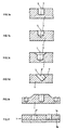
- FIG. 1 shows a target according to the invention made of ferromagnetic Material, in particular made of nickel or one Nickel alloy, such as NiFe, on its atomizing surface Pattern of blind holes.
- These can be in the target plate 1, as shown for example with reference to FIGS. 1a to 1c, be incorporated, for example be drilled.
- the blind holes 3 are rotationally symmetrical to the axis L.
- the blind holes provided according to the invention can 3, as shown at 3 ', also at an oblique angle with respect the new atomization surface 7 of the target incorporated his.
- the thickness expansion of the target 1 can when executing the blind holes provided according to the invention according to one or more of those shown with reference to FIGS. 1a to 1d Embodiments are tiered, which also the The course of the tunnel field is influenced.
- the target is again provided with blind holes 1a to 1d, formed in two parts with an upper plate 1a and a lower 1b, preferably made of the same materials.
- the top plate 1a is for Creation of blind holes 3 "drilled. This can e.g. bring significant manufacturing advantages.
- FIG. 2 schematically shows a section of a magnetron source according to the invention with a target 1 according to the invention. Dashed lines represent one of the several blind holes 3 provided according to the invention.
- the magnet arrangement 5 generates the tunnel-shaped stray field B ,
- the distribution of the intended Blind holes 3 in the Targetz sputtering area the tunnel field can be influenced in a targeted manner, in order to the dusting rate itself or to specifically design the resulting erosion profile.
- a circular target according to the invention is shown in a simple embodiment.
- a pattern of blind holes 3 is provided according to the invention, preferably defining a self-contained loop, preferably also a circular loop in T.
- FIG. 4 shows an end section of a rectangular target in a top view.
- four loops of blind holes 3 are provided here, an outermost 11 a and an innermost 11 i with blind holes of larger diameter.
- two loop patterns 13 a and 13 i of blind holes of smaller diameter are provided here, an outermost 11 a and an innermost 11 i with blind holes of larger diameter.
- An arrangement with several loop patterns in or close to T makes it possible, for example, to realize an optimally homogeneous field B rx .
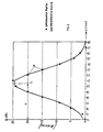
- ⁇ B x is recorded at a height of 5 mm above a 4 mm single hole in an 11 mm thick Ni target using a magnet system as used on the AK 517 magnetron source, which is sold by the applicant.
- FIG. 6 shows the course of the magnetic field increase ⁇ B x in a z / x plane, which is similar to the Gaussian function, in FIG. 6,
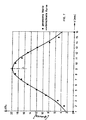
- FIG. 7 shows the comparison mentioned at the same single blind hole, viewed in the z / y plane, in each case by L ,
- the diameter 4mm (a), 5mm (b), 6mm (c) in the 11mm Ni target when using the mentioned magnet system is the maximum magnetic field increase ⁇ B xmax , measured over 5mm of the new surface and the respective hole center L shown.
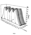
- B rx shows the resulting magnetic field B rx if, with the corresponding offset V 1 to V 4 in T and centered with respect to the y tunnel axis, four blind holes are provided, each with a diameter of 4 mm, again in an 11 mm diameter. thick Ni target and with the mentioned magnet arrangement. It can be seen from this that B rx , measured or calculated here at a height of 5 mm above the atomizing surface, can be determined by additive superimposition of the Gaussian-like distributions of B lx and ⁇ B x of the individual blind holes.
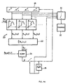
- a computer 20 receives from a given number n individual blind holes with a given magnetic field B xo (x, y) distribution, with a given offset V 1-n , a given diameter der 1-n and the given y position y 1-n , For a given hole profile and inclined position and given target thickness, enter the measured or calculated single- hole magnetic fields B lx1-n . These are additively superimposed on the computing unit 22.
- the course of the magnetic field B rx (x, y) results. This corresponds to the summation of the single-hole magnetic field profiles, for example according to FIG. 5, to the resulting magnetic field profile, for example according to FIG. 9.
- the calculated resulting curve B xr (x, y) is compared at a comparison unit 24 with a predetermined, desired TARGET curve B lxSOLL (x, y).
- the hole offsets V 1-n and / or the diameter ⁇ 1-n and / or the hole positions x, y and / or the hole profile and / or the hole inclined positions and / or the target thickness changed until the resulting field distribution B rx (x, y) with the required accuracy the nominal course rxSOLL B (x, y).
- the iterative feedback process ⁇ is interrupted, the geometric data then determined for position, profile, inclined position, thickness and hole diameter, as shown schematically with the switching unit 30, optionally via intermediate storage, to a machine tool 32 for transmit the target perforation.
- the aim is to achieve the highest possible stray field strength, and furthermore the widest possible stray field profile over the new target area.
- the hole parameters mentioned namely geometric position, profile, inclined position, local thickness of the target plate, preferably varied, but also the number of holes used n in order to achieve the TARGET profile with the required approximation, with the lowest possible number of blind holes.
- empirical values about the corresponding course of the target erosion are taken into account.
- FIG. 10 shows the measured NZ on a device according to the invention structured Ni target of 11mm thickness with the extension 5 " x 17 ", and designed as shown in Fig. 4, worn, from which it can be seen that as a function of the target operating time in kWh the sputtered material rate used is only insignificant decreases and thus the loss rate is only insignificant increases.
- N was measured with 18% Ni targets according to the invention, compared to only 13% for unstructured Ni targets.
- targets according to the invention made of ferromagnetic material it becomes possible to use much thicker target plates and thus significantly extend the target service life. Provision of a carrier plate for the target is unnecessary often.
- the erosion trenches are profiled compared to non-blind holes Targets made of the same ferromagnetic material, little constricted. This results in a significant increase from N.
- the creation of a hole pattern in the target is extremely cost-effective, and by the manufacturing method according to the invention can selectively desired field courses of the tunnel field will be realized.
- Fig. 12 is a particularly preferred pattern displayed on a rectangular target. It includes rows of holes 40, which, along the long sides of the target, zigzag are arranged inside.
- the outer holes 3a, preferably two each, and the inner 3i, again preferably two, are larger than the middle holes 3m, again preferably two.
- the diameter of the holes 3a, 3i is preferably 5mm, that of the holes 3m 4mm.
- the Holes 3 are in turn arranged in loop legs 11c.
- the pattern is essentially along the broad sides of the target segment of a circle, as shown at 4, preferably spanned by rows of holes 3m, 3a parallel to the target broadside. This pattern gives you one particularly shallow erosion trench, which is independent of the Target thickness is.
Landscapes
- Chemical & Material Sciences (AREA)
- Engineering & Computer Science (AREA)
- Organic Chemistry (AREA)
- Materials Engineering (AREA)
- Mechanical Engineering (AREA)
- Metallurgy (AREA)
- Chemical Kinetics & Catalysis (AREA)
- Physics & Mathematics (AREA)
- Plasma & Fusion (AREA)
- Analytical Chemistry (AREA)
- Physical Vapour Deposition (AREA)
- Powder Metallurgy (AREA)
- Thin Magnetic Films (AREA)
Description
- Fig. 1a bis 1f
- je einen Ausschnitt aus einem erfindungsgemässen Target, jeweils mit einer Ausführungsform der erfindungsgemäss vorgesehenen Sackbohrungen;
- Fig. 2
- schematisch einen Ausschnitt aus einer erfindungsgemässen Magnetronquelle mit einem erfindungsgemässen Target, auch zur Definition der in der Beschreibung verwendeten Grössen;
- Fig. 3
- eine bevorzugte Ausführungsform eines erfindungsgemässen Rundtargets mit Minimallochmusterung;
- Fig. 4
- die Aufsicht auf ein erfindungsgemässes Rechtecktarget mit verbesserter Lochmusterung;
- Fig. 5
- die berechnete Streufeldüberhöhung an einem versetzten Einzelsackloch am Target der Quelle nach Fig. 2;
- Fig. 6
- den Vergleich der nach Fig. 5 berechneten Streufeldüberhöhung mit der gemessenen, in x-Richtung eines x/y/z-Koordinatensystems (s. Definitionen);
- Fig. 7
- eine Darstellung analog zu Fig. 6, betrachtet in y-Richtung;
- Fig. 8
- den Verlauf der maximalen Streufeldüberhöhung an drei Einzelsacklöchern unterschiedlicher Durchmesser bei unterschiedlichem Versatz (s. Definitionen);
- Fig. 9
- den bei vier nebeneinanderliegenden Sacklöchern durch Ueberlagerung resultierenden Magnetfeldverlauf;
- Fig. 10
- den Verlauf der Nutzzerstäubungsrate an einem gemäss Fig. 4 strukturierten Nickeltarget in Funktion der Targetlebensdauer;
- Fig. 11
- ein Funktionsblock/Signalflussdiagramm einer nach dem erfindungsgemässen Verfahren arbeitenden erfindungsgemässen Targetherstellanlage und
- Fig. 12
- eine besonders bevorzugte Ausführungsform eines erfindungsgemässen Rechtecktargets in einer Darstellung analog zu Fig. 4.
- Tunnelfeld: Das Gesamtfeldmuster des aus der Targetzerstäubungsfläche
austretenden und in
diese wieder eintretenden magnetischen
Streufeldes
B der Magnetronquelle, mit Komponente Bz senkrecht zur Zerstäubungsneufläche 7 und der Komponente Bx parallel zur Neufläche 7. Die FeldlinienB verlaufen in jeweiligen Ebenen E senkrecht zur Neufläche 7. - Tunnelachse y: entsprechend Koordinatenachse y: Ort auf der Neufläche 7, worüber Bx maximal ist und Bz verschwindend.
- x-Koordinate x/y/z-System: mit dem Ursprung auf der Tunnelachse y, senkrecht zu y in der Neufläche 7. Daraus ergibt sich das System x/y/z.
- Erosionsgraben 9: Der sich im wesentlichen unter dem
Bereich T des Tunnelfeldes
B erstreckende, zunehmend tiefe Bereich abgestäubten Materials. - Neufläche 7: Unzerstäubte Targetzerstäubungsfläche.
- Feldstärke B ox: Die sich bei nicht gelochter Neufläche 7 unmittelbar an ihrer Oberfläche ergebende Feldstärkekomponente in x-Richtung.
- B ℓx: Die sich im Bereich eines erfindungsgemäss vorgesehenen Sackloches einstellende Feldstärke in x-Richtung.
- B ℓxmax: Deren Maximalwert.
ΔB x: Streufeldüberhöhung, die Differenz des an einem Ort im Bereiche eines erfindungsgemäss vorgesehenen Sackloches gemessenen Feldes Bℓx und dem am gleichen Orte gemessenen Feldes Box. - B rx: Der bei Vorsehen mehrerer Sacklöcher daraus resultierende Feldverlauf in x-Richtung.
- Lochversatz V: Der Versatz der Zentralachse L eines erfindungsgemäss vorgesehenen Sackloches senkrecht zur Tunnelachse y.
- Nutzzerstäubungsrate NZ: Die pro kWh elektrische Leistung zerstäubte und über dem Target nutzbare Materialmenge in g.
- Nutzungsgrad N: In Prozent, der Anteil des über der erodierten Targetfläche nutzbaren zerstäubten Materials, bezogen auf das Neugewicht des Targets.
Claims (14)
- Magnetrontarget aus ferromagnetischem Material, dadurch gekennzeichnet, dass es, entlang seiner Zerstäubungsfläche verteilt, ein Muster von Sacklöchern (3) aufweist.
- Magnetrontarget nach Anspruch 1, dadurch gekennzeichnet, dass die Sacklöcher (3) im wesentlichen entlang mindestens einer in sich geschlossenen Schleife (11, 13), vorzugsweise bezüglich des Targetoberflächenzentrums und/oder mindestens einer Targetoberflächen-Symmetrieachse zentriert, angeordnet sind, vorzugsweise in mindestens zwei der erwähnten in sich geschlossenen Schleifen.
- Target nach Anspruch 2, dadurch gekennzeichnet, dass zwischen zwei (11a, 11i) in sich geschlossenen Schleifen mindestens eine (13a, 13i) weitere vorgesehen ist, wobei vorzugsweise die Sackloch-Durchmesser der Sacklöcher (3) entlang der weiteren Schleife (13a, 13i) kleiner sind als die entlang der zwei äusseren Schleifen (11a, 11i).
- Target nach einem der Ansprüche 1 bis 3, dadurch gekennzeichnet, dass das Muster sich zick-zack-förmig vom Targetflächen-Rand zu deren Zentrum hin erstreckende Reihen (40) von Sacklöchern (3) umfasst.
- Target nach Anspruch 4, dadurch gekennzeichnet, dass es rechteckförmig ist, sich das Zick-zack-Muster quer zu und entlang der Längsseiten erstreckt und dass entlang der Breitseiten das Muster mindestens genähert in Form einer Kreissegmentfläche (4) die Zick-zack-Muster verbindet.
- Target nach Anspruch 4 oder 5, dadurch gekennzeichnet, dass die Reihen aus Sackbohrungen bestehen, deren äussere (3a) einen grösseren Durchmesser aufweisen als deren innere (3m).
- Target nach einem der Ansprüche 1 bis 6, dadurch gekennzeichnet, dass es aus Nickel oder einer Nickellegierung, vorzugsweise bei letzterem aus NiFe besteht.
- Target nach einem der Ansprüche 1 bis 7, dadurch gekennzeichnet, dass die Sackloch-Durchmesser im Bereich von 3mm bis 6mm (beide Grenzen eingeschlossen) liegen.
- Magnetronquelle mit einem Target nach einem der Ansprüche 1 bis 8, dadurch gekennzeichnet, dass die Sacklochverteilung sich entlang desjenigen Targetbereiches erstreckt, worüber das Tunnelfeld (
B ) der Quelle liegt. - Magnetronquelle nach Anspruch 9, dadurch gekennzeichnet, dass die Sacklochverteilung im wesentlichen symmetrisch zum Ort verschwindender Magnetfeldstärkekomponente (Bz) senkrecht zur Targetneufläche (7) des Tunnelfeldes ist.
- Magnetronsputteranlage mit einer Magnetronquelle nach einem der Ansprüche 9 oder 10, dadurch gekennzeichnet, dass die Durchmesser der Sacklöcher so dimensioniert sind, dass keine Hohlkathodenentladung bei Betriebsbedingungen der Anlage auftritt.
- Verfahren zur Herstellung eines Targets aus ferromagnetischem Material für eine gegebene Magnetronquelle mit gegebenem Tunnelfeld, dadurch gekennzeichnet, dass manden Tunnelfeldverlauf bei Vorsehen einzelner Sacklöcher in der Targetneufläche in Funktion von Lochdurchmesser und/oder ihrer Relativlage zum Tunnelfeld und/oder des Lochprofils und/oder der Lochachsenneigung bezüglich der Targetneufläche und/oder der Targetdickenprofilierung misst oder berechnet und abspeichert,diese Tunnelfeldverläufe mehrerer Einzelsacklöcher bei gegebenen Relativlagen zwischen den Löchern und zum Tunnelfeld und Lochdurchmessern, als Anfangsbedingungen, additiv überlagert zum Erhalt eines resultierenden Tunnelfeldverlaufes,den resultierenden Tunnelfeldverlauf mit einem SOLL-Tunnelfeldverlauf vergleicht,in Funktion des Vergleichsresultates die Parameter-Relativlage der Einzelsacklöcher und/oder ihre Durchmesser und/oder ihre Lage bezüglich des Tunnelfeldes und/oder ihr Profil und/oder ihre Neigung und/oder die Targetdickenprofilierung und/oder die Lochanzahl so lange verändert, bis das resultierende Feld mit gegebener Näherung dem SOLL-Feldverlauf entspricht,mit den gefundenen Parametern das Einarbeiten von Sacklöchern in die plane Targetzerstäubungsfläche steuert.
- Anordnung zur Herstellung eines Targets aus ferromagnetischem Material für eine gegebene Magnetronquelle mit gegebenem Tunnelfeld, dadurch gekennzeichnet, dass sie umfassteine Eingabeeinheit mit mehreren Ausgängen, woran Feldverteilungskurven abrufbar sind und woran (26), über Stelleingänge, Kurvenparameter (n, v, Φ, y) verstellbar sind,eine Verlaufsadditionseinheit (22), welche eingangsseitig mit der Eingabeeinheit wirkverbunden ist und welche ausgangsseitig auf den einen Eingang einer Verlaufsvergleichseinheit (24) führt, an deren zweitem Eingang ein erwünschter Verlauf eingebbar ist und deren Ausgang auf die Stelleingänge an der Eingabeeinheit (26) rückwirkt, wobei weiter die Stelleingänge gesteuert mit einer Ausgabe (30, 32) für die Ansteuerung einer Sacklochfertigungseinrichtung für das Target wirkverbunden sind.
- Anordnung nach Anspruch 13, dadurch gekennzeichnet, dass an der Eingabeeinheit die Anzahl (n) aktivierter Ausgänge über die Stelleingänge verstellbar ist.
Applications Claiming Priority (4)
| Application Number | Priority Date | Filing Date | Title |
|---|---|---|---|
| CH72496 | 1996-03-19 | ||
| CH72496 | 1996-03-19 | ||
| CH724/96 | 1996-03-19 | ||
| PCT/CH1997/000114 WO1997035043A1 (de) | 1996-03-19 | 1997-03-19 | Target, magnetronquelle mit einem solchen und verfahren zur herstellung eines solchen targets |
Publications (2)
| Publication Number | Publication Date |
|---|---|
| EP0888464A1 EP0888464A1 (de) | 1999-01-07 |
| EP0888464B1 true EP0888464B1 (de) | 2002-10-02 |
Family
ID=4193707
Family Applications (1)
| Application Number | Title | Priority Date | Filing Date |
|---|---|---|---|
| EP97906078A Expired - Lifetime EP0888464B1 (de) | 1996-03-19 | 1997-03-19 | Target, magnetronquelle mit einem solchen und verfahren zur herstellung eines solchen targets |
Country Status (6)
| Country | Link |
|---|---|
| US (1) | US6312574B1 (de) |
| EP (1) | EP0888464B1 (de) |
| JP (1) | JP2000506567A (de) |
| AT (1) | ATE225415T1 (de) |
| DE (1) | DE59708376D1 (de) |
| WO (1) | WO1997035043A1 (de) |
Families Citing this family (2)
| Publication number | Priority date | Publication date | Assignee | Title |
|---|---|---|---|---|
| US6709557B1 (en) | 2002-02-28 | 2004-03-23 | Novellus Systems, Inc. | Sputter apparatus for producing multi-component metal alloy films and method for making the same |
| US6830664B2 (en) * | 2002-08-05 | 2004-12-14 | Tegal Corporation | Cluster tool with a hollow cathode array |
Family Cites Families (11)
| Publication number | Priority date | Publication date | Assignee | Title |
|---|---|---|---|---|
| US4299678A (en) * | 1979-07-23 | 1981-11-10 | Spin Physics, Inc. | Magnetic target plate for use in magnetron sputtering of magnetic films |
| CH649578A5 (de) * | 1981-03-27 | 1985-05-31 | Ulvac Corp | Hochgeschwindigkeits-kathoden-zerstaeubungsvorrichtung. |
| DE3149910A1 (de) * | 1981-12-16 | 1983-06-23 | Siemens AG, 1000 Berlin und 8000 München | Vorrichtung zur kathodenzerstaeubung von mindestens zwei verschiedenen materialien |
| DE3223245C2 (de) * | 1982-07-23 | 1986-05-22 | Nihon Shinku Gijutsu K.K., Chigasaki, Kanagawa | Ferromagnetische Hochgeschwindigkeits-Kathodenzerstäubungs-Vorrichtung |
| JPS61105610A (ja) * | 1984-10-27 | 1986-05-23 | Citizen Watch Co Ltd | 数値制御工作機械の自動プログラミング装置 |
| US4637853A (en) * | 1985-07-29 | 1987-01-20 | International Business Machines Corporation | Hollow cathode enhanced plasma for high rate reactive ion etching and deposition |
| AT388752B (de) * | 1986-04-30 | 1989-08-25 | Plansee Metallwerk | Verfahren zur herstellung eines targets fuer die kathodenzerstaeubung |
| JPS63118067A (ja) * | 1986-11-05 | 1988-05-23 | Tokin Corp | スパツタリングタ−ゲツト |
| US4915810A (en) * | 1988-04-25 | 1990-04-10 | Unisys Corporation | Target source for ion beam sputter deposition |
| US4865708A (en) * | 1988-11-14 | 1989-09-12 | Vac-Tec Systems, Inc. | Magnetron sputtering cathode |
| US4879017A (en) * | 1988-11-29 | 1989-11-07 | Dae Ryung Vacumm Co. Ltd. | Multi-rod type magnetron sputtering apparatus |
-
1997
- 1997-03-19 DE DE59708376T patent/DE59708376D1/de not_active Expired - Lifetime
- 1997-03-19 JP JP9533009A patent/JP2000506567A/ja not_active Ceased
- 1997-03-19 WO PCT/CH1997/000114 patent/WO1997035043A1/de not_active Ceased
- 1997-03-19 EP EP97906078A patent/EP0888464B1/de not_active Expired - Lifetime
- 1997-03-19 AT AT97906078T patent/ATE225415T1/de active
-
1998
- 1998-09-21 US US09/157,408 patent/US6312574B1/en not_active Expired - Lifetime
Also Published As
| Publication number | Publication date |
|---|---|
| JP2000506567A (ja) | 2000-05-30 |
| ATE225415T1 (de) | 2002-10-15 |
| US6312574B1 (en) | 2001-11-06 |
| DE59708376D1 (de) | 2002-11-07 |
| WO1997035043A1 (de) | 1997-09-25 |
| EP0888464A1 (de) | 1999-01-07 |
Similar Documents
| Publication | Publication Date | Title |
|---|---|---|
| DE69104131T2 (de) | Drehkathode. | |
| EP0169402B1 (de) | Gesteinsbohrer | |
| EP2622113B1 (de) | Beschichten von substraten mit einer legierung mittels kathodenzerstäubung | |
| DE69704989T2 (de) | Ein elektromagnetisch betätigbares Ventil | |
| CH659484A5 (de) | Anordnung zur beschichtung von substraten mittels kathodenzerstaeubung. | |
| DE3124599A1 (de) | "verfahren und vorrichtung zum zerstaeuben mit magnetischer verstaerkung sowie zur beschichtung eines substrats" | |
| DE4117367C2 (de) | Verfahren zur Erzeugung eines homogenen Abtragprofils auf einem rotierenden Target einer Sputtervorrichtung | |
| CH658750A5 (de) | Hochgeschwindigkeits-zerstaeubungsvorrichtung. | |
| DE9301065U1 (de) | Target für eine Kathodenzerstäubungsvorrichtung | |
| WO2004057642A2 (de) | Vacuumarcquelle mit magnetfelderzeugungseinrichtung | |
| WO1997041587A1 (de) | Sputteranlage mit zwei längserstreckten magnetrons | |
| DE60104709T2 (de) | Zerstäubungstarget | |
| DE3336405A1 (de) | Verfahren zum aufbau einer wanderwellenroehre mit gekoppelten hohlraeumen | |
| DE2940369C2 (de) | Target | |
| DE4133251C2 (de) | Verfahren zum Herstellen eines Flammenhalters für einen Strahlungsbrenner und nach diesem Verfahren hergestellter Flammenhalter | |
| DE9310565U1 (de) | Target für Kathodenzerstäubungsanlagen | |
| EP2558608B1 (de) | Lichtbogenverdampfungs-beschichtungsquelle | |
| EP0888464A1 (de) | Target, magnetronquelle mit einem solchen und verfahren zur herstellung eines solchen targets | |
| DE3442206C2 (de) | ||
| EP1118832B1 (de) | Verfahren zur Innenbeschichtung eines Waffenrohres | |
| DE102019113092A1 (de) | Sputterkathode-Magnetsystem und Vakuumanordnung | |
| WO2000016373A1 (de) | Targetanordnung für eine arc-verdampfungs-kammer | |
| DE20302566U1 (de) | Lötspitze | |
| DE3128248C2 (de) | ||
| EP3583619B1 (de) | Lichtbogenkathodenverdampfung mit vorbestimmtem kathodenmaterialabtrag |
Legal Events
| Date | Code | Title | Description |
|---|---|---|---|
| PUAI | Public reference made under article 153(3) epc to a published international application that has entered the european phase |
Free format text: ORIGINAL CODE: 0009012 |
|
| 17P | Request for examination filed |
Effective date: 19980820 |
|
| AK | Designated contracting states |
Kind code of ref document: A1 Designated state(s): AT BE CH DE DK ES FR GB IE IT LI NL PT SE |
|
| 17Q | First examination report despatched |
Effective date: 19991207 |
|
| RAP1 | Party data changed (applicant data changed or rights of an application transferred) |
Owner name: UNAXIS BALZERS AKTIENGESELLSCHAFT |
|
| GRAG | Despatch of communication of intention to grant |
Free format text: ORIGINAL CODE: EPIDOS AGRA |
|
| GRAG | Despatch of communication of intention to grant |
Free format text: ORIGINAL CODE: EPIDOS AGRA |
|
| GRAH | Despatch of communication of intention to grant a patent |
Free format text: ORIGINAL CODE: EPIDOS IGRA |
|
| GRAH | Despatch of communication of intention to grant a patent |
Free format text: ORIGINAL CODE: EPIDOS IGRA |
|
| GRAH | Despatch of communication of intention to grant a patent |
Free format text: ORIGINAL CODE: EPIDOS IGRA |
|
| GRAA | (expected) grant |
Free format text: ORIGINAL CODE: 0009210 |
|
| AK | Designated contracting states |
Kind code of ref document: B1 Designated state(s): AT BE CH DE DK ES FR GB IE IT LI NL PT SE |
|
| REF | Corresponds to: |
Ref document number: 225415 Country of ref document: AT Date of ref document: 20021015 Kind code of ref document: T |
|
| REG | Reference to a national code |
Ref country code: GB Ref legal event code: FG4D Free format text: NOT ENGLISH |
|
| REG | Reference to a national code |
Ref country code: CH Ref legal event code: EP |
|
| REG | Reference to a national code |
Ref country code: IE Ref legal event code: FG4D Free format text: GERMAN |
|
| REF | Corresponds to: |
Ref document number: 59708376 Country of ref document: DE Date of ref document: 20021107 |
|
| PG25 | Lapsed in a contracting state [announced via postgrant information from national office to epo] |
Ref country code: SE Free format text: LAPSE BECAUSE OF FAILURE TO SUBMIT A TRANSLATION OF THE DESCRIPTION OR TO PAY THE FEE WITHIN THE PRESCRIBED TIME-LIMIT Effective date: 20030102 Ref country code: PT Free format text: LAPSE BECAUSE OF FAILURE TO SUBMIT A TRANSLATION OF THE DESCRIPTION OR TO PAY THE FEE WITHIN THE PRESCRIBED TIME-LIMIT Effective date: 20030102 Ref country code: DK Free format text: LAPSE BECAUSE OF FAILURE TO SUBMIT A TRANSLATION OF THE DESCRIPTION OR TO PAY THE FEE WITHIN THE PRESCRIBED TIME-LIMIT Effective date: 20030102 |
|
| GBT | Gb: translation of ep patent filed (gb section 77(6)(a)/1977) |
Effective date: 20030109 |
|
| ET | Fr: translation filed | ||
| PG25 | Lapsed in a contracting state [announced via postgrant information from national office to epo] |
Ref country code: ES Free format text: LAPSE BECAUSE OF FAILURE TO SUBMIT A TRANSLATION OF THE DESCRIPTION OR TO PAY THE FEE WITHIN THE PRESCRIBED TIME-LIMIT Effective date: 20030429 |
|
| PLBE | No opposition filed within time limit |
Free format text: ORIGINAL CODE: 0009261 |
|
| STAA | Information on the status of an ep patent application or granted ep patent |
Free format text: STATUS: NO OPPOSITION FILED WITHIN TIME LIMIT |
|
| 26N | No opposition filed |
Effective date: 20030703 |
|
| PGFP | Annual fee paid to national office [announced via postgrant information from national office to epo] |
Ref country code: CH Payment date: 20140312 Year of fee payment: 18 Ref country code: NL Payment date: 20140308 Year of fee payment: 18 |
|
| PGFP | Annual fee paid to national office [announced via postgrant information from national office to epo] |
Ref country code: IT Payment date: 20140314 Year of fee payment: 18 Ref country code: AT Payment date: 20140226 Year of fee payment: 18 Ref country code: FR Payment date: 20140311 Year of fee payment: 18 |
|
| PGFP | Annual fee paid to national office [announced via postgrant information from national office to epo] |
Ref country code: BE Payment date: 20140312 Year of fee payment: 18 |
|
| REG | Reference to a national code |
Ref country code: CH Ref legal event code: PL |
|
| REG | Reference to a national code |
Ref country code: AT Ref legal event code: MM01 Ref document number: 225415 Country of ref document: AT Kind code of ref document: T Effective date: 20150319 |
|
| REG | Reference to a national code |
Ref country code: NL Ref legal event code: MM Effective date: 20150401 |
|
| PG25 | Lapsed in a contracting state [announced via postgrant information from national office to epo] |
Ref country code: IT Free format text: LAPSE BECAUSE OF NON-PAYMENT OF DUE FEES Effective date: 20150319 |
|
| REG | Reference to a national code |
Ref country code: FR Ref legal event code: ST Effective date: 20151130 |
|
| PG25 | Lapsed in a contracting state [announced via postgrant information from national office to epo] |
Ref country code: CH Free format text: LAPSE BECAUSE OF NON-PAYMENT OF DUE FEES Effective date: 20150331 Ref country code: LI Free format text: LAPSE BECAUSE OF NON-PAYMENT OF DUE FEES Effective date: 20150331 |
|
| PG25 | Lapsed in a contracting state [announced via postgrant information from national office to epo] |
Ref country code: FR Free format text: LAPSE BECAUSE OF NON-PAYMENT OF DUE FEES Effective date: 20150331 Ref country code: AT Free format text: LAPSE BECAUSE OF NON-PAYMENT OF DUE FEES Effective date: 20150319 |
|
| PGFP | Annual fee paid to national office [announced via postgrant information from national office to epo] |
Ref country code: IE Payment date: 20160309 Year of fee payment: 20 Ref country code: DE Payment date: 20160315 Year of fee payment: 20 |
|
| PGFP | Annual fee paid to national office [announced via postgrant information from national office to epo] |
Ref country code: GB Payment date: 20160316 Year of fee payment: 20 |
|
| REG | Reference to a national code |
Ref country code: DE Ref legal event code: R071 Ref document number: 59708376 Country of ref document: DE |
|
| REG | Reference to a national code |
Ref country code: GB Ref legal event code: PE20 Expiry date: 20170318 |
|
| REG | Reference to a national code |
Ref country code: IE Ref legal event code: MK9A |
|
| PG25 | Lapsed in a contracting state [announced via postgrant information from national office to epo] |
Ref country code: GB Free format text: LAPSE BECAUSE OF EXPIRATION OF PROTECTION Effective date: 20170318 |
|
| PG25 | Lapsed in a contracting state [announced via postgrant information from national office to epo] |
Ref country code: NL Free format text: LAPSE BECAUSE OF NON-PAYMENT OF DUE FEES Effective date: 20150401 |
|
| PG25 | Lapsed in a contracting state [announced via postgrant information from national office to epo] |
Ref country code: BE Free format text: LAPSE BECAUSE OF NON-PAYMENT OF DUE FEES Effective date: 20150331 Ref country code: IE Free format text: LAPSE BECAUSE OF EXPIRATION OF PROTECTION Effective date: 20170319 |