EP0888072B1 - Brushes and process for producing the same - Google Patents
Brushes and process for producing the same Download PDFInfo
- Publication number
- EP0888072B1 EP0888072B1 EP96923964A EP96923964A EP0888072B1 EP 0888072 B1 EP0888072 B1 EP 0888072B1 EP 96923964 A EP96923964 A EP 96923964A EP 96923964 A EP96923964 A EP 96923964A EP 0888072 B1 EP0888072 B1 EP 0888072B1
- Authority
- EP
- European Patent Office
- Prior art keywords
- bristles
- brush
- bundles
- brush body
- supporting
- Prior art date
- Legal status (The legal status is an assumption and is not a legal conclusion. Google has not performed a legal analysis and makes no representation as to the accuracy of the status listed.)
- Expired - Lifetime
Links
Images


Classifications
-
- A—HUMAN NECESSITIES
- A46—BRUSHWARE
- A46B—BRUSHES
- A46B3/00—Brushes characterised by the way in which the bristles are fixed or joined in or on the brush body or carrier
- A46B3/16—Brushes characterised by the way in which the bristles are fixed or joined in or on the brush body or carrier by wires or other anchoring means, specially for U-shaped bristle tufts
-
- A—HUMAN NECESSITIES
- A46—BRUSHWARE
- A46B—BRUSHES
- A46B9/00—Arrangements of the bristles in the brush body
- A46B9/08—Supports or guides for bristles
- A46B9/12—Non-adjustable supports
-
- A—HUMAN NECESSITIES
- A46—BRUSHWARE
- A46B—BRUSHES
- A46B2200/00—Brushes characterized by their functions, uses or applications
- A46B2200/10—For human or animal care
- A46B2200/1066—Toothbrush for cleaning the teeth or dentures
Definitions
- the present invention relates to a method for producing a brush, in particular Toothbrush with a bristle bundle carrying brush body, the bristle bundle consist of plastic bristles.
- the present invention further relates to a Brush, in particular toothbrush, with a brush body carrying bristle bundles, the bristle bundles consisting of plastic bristles at least in part are each surrounded by sleeve-shaped support elements.
- a brush of the type mentioned is known from DE-PS 538 075.
- Toothbrushes are bundles of bristles in rubber sleeves that are housed in a body are used and include tufts of natural bristles or animal hair.
- the rubber sleeves in one Basic body used To produce the previously known toothbrush is therefore a considerable one Effort required.
- the previously known toothbrush has the Disadvantage that dirt and / or bacteria between the body and the can stick in the rubber sleeves used. The previously known toothbrush Accordingly, it does not meet today's hygienic requirements.
- the object of the present invention is a method To create a brush with brushes, especially toothbrushes can be economically manufactured to meet today's hygienic requirements are enough.
- the present invention is also based on the object of a brush, and in particular to create a toothbrush of the type mentioned that is economical is producible and spreading the bristle bundles on their usage side Ends, which leads to a reduced usability of the brush, and at Toothbrushes are not medically recommended to oppose resistance.
- the solution according to the invention therefore allows softer bristles or bundles of bristles to be used as before. Especially can now thinner bristles or softer bristle materials, or a combination of both become. This will be a gentler and above all very allows much more thorough brushing of the teeth and the danger injuries to the oral cavity, and especially the gums, decreased.
- the one that is clearly perceptible to the user Deformation of the bristles during cleaning also reduces too high contact pressure when cleaning, because too much Deformation of the bristle bundles involuntarily by the user will be recognized as wrong and will be corrected immediately.
- the brush thus supports a medically correct one Brush your teeth. It will also make cleaning more effective achieved because by using thinner bristles the number the bristles per bundle can be increased and thus more bristle ends are effectively engaged. This is preferably done Side support of the bristle bundles elastic.
- the invention can be used for brushes with a bristle bundle as well as with brushes with a multitude of bristle bundles be used.
- the use of the brush according to the invention is not on the dental field or limited the cosmetics area. Rather, such Brushing in all areas of everyday life and technology be used, preferably where a particular gentle cleaning of relief-like surface formations is required and / or a particularly long service life of the Bristles is desired.
- each bristle bundle There is preferably a separate support element for each bristle bundle intended. This enables, with appropriate Selection of the support element in terms of its shape and Deformation capacity, the bending characteristic of individual bristle bundles individually set. For example on a toothbrush with several rows of bristles Bristle bundle or the front bristle bundle supported by higher rigidity than the remaining. It is also conceivable that only a part to support the bristle bundle by means of supporting elements which remaining, however, remain unsupported.
- the support elements become integral with one another connected and attached as a support unit on the brush body.
- the shape and the Deformation capacity of the respective support element of a bristle bundle can be set individually the integral design simpler manufacture of the support elements, since these are produced according to the invention using an injection molding process become.
- the support element preferably has an elastic sleeve section in which a bristle receiving opening extends, and a base portion over which the sleeve portion is connected to the brush body.
- a support of the bristle bundles in a solid material body for example a support plate of constant thickness
- Support areas around the individual bristle bundles can through the formation of sleeve-like support elements more precise setting of direction-dependent deformation properties of the respective support element and a higher degree of deformation be achieved. Due to a flange-like expansion of the base section of the support element can be the contact surface between the brush body and the support element be enlarged to loosen the support element even better to prevent.
- the bristle bundles are preferably fastened in the bristle body, whereby the individual bristle bundles are characterized by the respective Extend support elements through. Alternatively, you can the bundles of bristles are only attached to the support elements be, between the bristle bundles and the support elements Group liability is achieved.
- the sleeve section or its outer contour be formed essentially cylindrical.
- the necessary Apply bevels and bends In the preparation of of the support element or elements in a form Specialist for easier removal from the mold the necessary Apply bevels and bends.
- the sleeve section can also be designed in this way be that its wall thickness at the end of use Bristles tapered.
- the bending characteristic of the Systems bristle bundle / support element influenced in the desired manner become.
- the shape of the outer sleeve can meet the requirements a desired bend line of the bristle bundle or individual bristles can be adjusted.
- an integral support element interconnected.
- the brush body can completely on the bristle side Integral support element are covered, resulting in a homogeneous Appearance and a high peel strength of the support elements leads.
- Such an integral support element can also be used manufacture in a particularly efficient manner.
- the support element can have a surface formation for enlargement the interface between the two are provided to to improve the peel strength.
- a corresponding increase in surface area can for example by corrugation on one or both parts.
- the attachment of Grooves, ribs, hole patterns or the like can be given.
- One way is to fold a bundle of bristles and then the folded end by means of an anchor in the brush body to fix.
- the anchor for example a plate-like one Metal or plastic part, can with that looped bristle bundle in a provided on the brush body Opening used, for example, punched.
- the bristles can also be made by that the ends of the bristle bundles to be fastened are melted be so that thickenings form. The thickening are then with brush body material or with support element material overmolded, so that the bristle bundles form-fitting being held.
- the brush can be used in a two-component injection molding process are produced, the brush body made of a hard plastic component and the support elements as a bristle border preferably made of a plastic soft component, for example consist of a thermoplastic elastomer, however can also be made from a hard component. Ideally, between the hard component of the brush body and the support element or the support elements composite adhesion realized. With appropriate material management can brush body and support elements in successive Manufacturing steps made in a single mold become.
- a brush body that can be formed in one piece with the handle of the brush 10 is with a variety of in any way producible blind holes 11 provided.
- Each of them serves Blind holes 11 for receiving a bundle of bristles 20 that a variety of, preferably thin, flexible bristles is made of plastic.
- This bundle of bristles 20 is folded or looped around an anchor 40, see that all bristle ends point in one direction.
- Each Bristle bundle is clawed in the brush body 11
- Anchor 40 clamped in its blind hole 11.
- the anchor is formed as a flat plate, which with respect to the Blind hole 11 essentially upright in the brush body 10 is stamped.
- the support element 30 On the bristle side of the brush body is for each bundle of bristles 20 attached a support member 30.
- the one in the figures 2a to 2c shown embodiment of the support element 30 has a bristle receiving opening 31 for lateral support of the bristle bundle 20.
- the bristle bundles are preferably supported up to about half their length.
- the Support element 30 has one in particular in the radial direction elastically deformable sleeve section 32 and one itself flange-like in the radial direction over the sleeve section 32 extending base portion 33. About this base section 33 is the respective support element 30 with the Brush body 10 connected. In the case of FIGS.
- 2a to 2c shown embodiment extends the bristle receiving opening 31 through the sleeve portion 32 and the base portion 33 through.
- the support element 30 or its base portion 33 and the brush body 10 shows a surface formation for enlarging the contact area provided between the two to ensure the peel strength of the respective support element to improve further. This can for example by corrugation or the attachment of grooves, ribs, hole patterns or similar on one or both contact surfaces respectively.
- Group liability can be achieved between the support elements 30 or their Base sections 33 and the brush body can with appropriate Material selection and suitable manufacturing parameters Group liability can be achieved.
- the individual support elements are mutually by their base sections 33 Connected to an integral support element and cover the brush body on the bristle side in the area of the bristles completely.
- the sleeve section 32 is essentially cylindrical, so that the bristle bundle the bending behavior is the same in all directions.
- the wall thickness of the sleeve section accordingly 32 and the arrangement of the bristle bundle 20 in the bristle receiving opening 31 allows the bending behavior of the bristle bundle / support element system in the desired manner and influence as needed.
- the outer bundles of bristles, and especially their outer bristles, more supported are called the inner bristles or bristle bundles, so that the durability of the most stressed bristles is further improved.
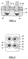
- the bending behavior of the bristle bundle 20 can the embodiment shown in Figures 2a to 2c also one only partial side support through the bristle receiving opening 31 be made, as is the case with the right Bristle bundle is shown in Fig.4.
- FIG Fig.3 Another embodiment of the support element 30 is shown in FIG Fig.3 shown.
- This support element differs from that shown in Figure 2a mainly by its essentially frustoconical formation.
- By decreasing the Wall thickness towards the end of the bristles can change the bending behavior of the bristle bundle / support element system is even more homogeneous than in the embodiment described above can be designed. In particular, this can stress the individual bristles further reduced in the exit area from the support element 30 become.
- the conical design results in the transition area of the sleeve section 32 to the base section 33 a lower notch effect, so that the Stability of the support member 30 is further improved.
- a separate support element can also be provided for each bundle of bristles 30, which is separated from the support elements of the other bristle bundles is to be provided.
- FIG Fig.4 Another embodiment of the support elements 30 is shown in FIG Fig.4 shown, which is integral with a solid body are trained. This results from the outside the impression of a conventional brush, but that already described advantages of the preferably elastic Has side support of the bristle bundle 20. How exemplary in the bristle bundle shown on the right in FIG. 4 this is only partially supported laterally to form a to achieve directional bending characteristics.
- blind holes 11 provided brush body 10, which preferably is injected from a hard plastic component the support elements 30 attached, for example by injection or also by an adhesive process or a Similar procedure, so that a deeper blind hole is created.
- the support element is preferably a two-component injection molding process used.
- the support elements 30 will make them out made of a plastic soft component. This gives a blind hole, the upper wall section one for the side support of the bristles has greater elasticity, and its lower part has sufficient strength for clawing of the armature 40.
- the bristle of the already is carried out with the support elements connected brush body 10 then by driving in the anchor 40 with the folds around it Bristles or bundles of bristles through the respective support element 30 through into the brush body 10 and there Clawing or jamming of the anchor and thus the bristle bundle 20th
- the bristle bundle 20 instructs its end to be anchored a thickening of melted Bristle material for sufficient bundle extraction worries.
- the thickened ends of the bristle bundles 20 in the brush body 10 attached.
- the individual Bristle bundle 20 introduced into prefabricated support elements 30, so that the thickenings 25 of the individual bristle bundles 20 protrude from the support members 30.
- the thickening are then made with a plastic hard component overmolded, which forms the brush body 10.
- the elastic side support of the bristle bundle 20 through the support elements 30 can also be through a plastic hard component (Material), their elasticity achieved by the shape of the individual support elements 30 becomes.
- plastic hard components are preferred for this, which have a Shore A hardness of less than 70, used.
- two-component process is not related to use limited by different materials but also includes the possibility of using the same material, for example with different colors.
Description
Die vorliegende Erfindung betrifft ein Verfahren zur Herstellung einer Bürste, insbesondere Zahnbürste mit einem Borstenbündel tragenden Bürstenkörper, wobei die Borstenbündel aus Kunststoffborsten bestehen. Die vorliegende Erfindung betrifft weiterhin eine Bürste, insbesondere Zahnbürste, mit einem Borstenbündel tragenden Bürstenkörper, wobei die aus Kunststoffborsten bestehenden Borstenbündel zumindest zu einem Teil jeweils von hülsenförmigen Stütztelementen umgeben sind.The present invention relates to a method for producing a brush, in particular Toothbrush with a bristle bundle carrying brush body, the bristle bundle consist of plastic bristles. The present invention further relates to a Brush, in particular toothbrush, with a brush body carrying bristle bundles, the bristle bundles consisting of plastic bristles at least in part are each surrounded by sleeve-shaped support elements.
Eine Bürste der eingangs genannten Art ist aus der DE-PS 538 075 bekannt. Bei dieser Zahnbürste sind Borstenbündel in Kautschuk-Hülsen aufgenommen, die in einen Grundkörper eingesetzt sind und Büschel aus Naturborsten bzw. Tierhaaren umfassen. Bei der aus dem Stand der Technik bekannten Zahnbürste sind die Kautschuk-Hülsen in einen Grundkörper eingesetzt. Zur Herstellung der vorbekannten Zahnbürste ist somit ein erheblicher Aufwand erforderlich. Darüber hinaus weist die vorbekannte Zahnbürste den Nachteil auf, daß sich Schmutz und/oder Bakterien zwischen dem Grundkörper und den in diesen eingesetzten Kautschuk-Hülsen festsetzen kann. Die vorbekannte Zahnbürste genügt dementsprechend nicht den heutigen hygienischen Anforderungen.A brush of the type mentioned is known from DE-PS 538 075. At this Toothbrushes are bundles of bristles in rubber sleeves that are housed in a body are used and include tufts of natural bristles or animal hair. In the Toothbrushes known from the prior art are the rubber sleeves in one Basic body used. To produce the previously known toothbrush is therefore a considerable one Effort required. In addition, the previously known toothbrush has the Disadvantage that dirt and / or bacteria between the body and the can stick in the rubber sleeves used. The previously known toothbrush Accordingly, it does not meet today's hygienic requirements.
Davon ausgehend liegt der vorliegenden Erfindung die Aufgabe zugrunde, ein Verfahren zur Herstellung einer Bürste zu schaffen, mit dem Bürsten, insbesondere Zahnbürsten wirschaftlich hergestellt werden können, die den heutigen hygienischen Anforderungen genügen. Der vorliegenden Erfindung liegt weiterhin die Aufgabe zugrunde, eine Bürste, und insbesondere eine Zahnbürste der eingangs genannten Art zu schaffen, die wirtschaftlich herstellbar ist und einem Aufspreizen der Borstenbündel an ihren nutzungsseitigen Enden, welches zu einer verminderten Brauchbarkeit der Bürste führt, und bei Zahnbürsten medizinisch nicht zu empfehlen ist, einen Widerstand entgegensetzt.Proceeding from this, the object of the present invention is a method To create a brush with brushes, especially toothbrushes can be economically manufactured to meet today's hygienic requirements are enough. The present invention is also based on the object of a brush, and in particular to create a toothbrush of the type mentioned that is economical is producible and spreading the bristle bundles on their usage side Ends, which leads to a reduced usability of the brush, and at Toothbrushes are not medically recommended to oppose resistance.
Die verfahrensmäßige Lösung der obigen Aufgabe wird durch das Verfahren gemäß Anspruch 1 gelöst. Bevorzugte Ausgestaltungen des erfindungsgemäßen Verfahrens sind in den Unteranspüchen 1 bis 11 angegeben.The procedural solution to the above object is achieved by the method according to claim 1 solved. Preferred configurations of the method according to the invention are specified in subclaims 1 to 11.
Die erfindungsgemäße Lösung bezüglich der Bürste ist in Anspruch 12 angegeben. Bevorzugte
Ausgestaltungen der erfindungsgemäße Bürste sind in den abhängigen Ansprüchen
13 bis 23 angegeben. The solution according to the invention with respect to the brush is specified in claim 12. Preferred
Embodiments of the brush according to the invention are in the
Die erfindungsgemäße Lösung bezüglich der Bürste ist in Anspruch 12 angegeben. Bevorzugte
Ausgestaltungen der erfindungsgemäßen Bürste sind in den abhängigen Ansprüchen
13 bis 23 angegeben.The solution according to the invention with respect to the brush is specified in claim 12. Preferred
Embodiments of the brush according to the invention are in the
Durch die Stützelemente wird ein verschleißbedingtes, bleibendes Ausweichen der Außenborsten von der ursprünglich vorgesehenen Stellung, zumindest im Bereich der Abstützung, unterbunden, so daß sich im Vergleich zu einer Bürste gleichen Verschleißgrades, jedoch ohne jegliche Abstützung, am Gebrauchsende der Borstenbündel eine geringere Aufspreizung ergibt, und somit eine längere Standzeit der Bürste ermöglicht wird.Through the support elements a wear-related, permanent evasion of the outer bristles from the original intended position, at least in the area of the support, prevented so that they look alike compared to a brush Degree of wear, but without any support, on End of use of the bristle bundles a smaller spread results, and thus enables a longer service life of the brush becomes.
Die erfindungsgemäße Lösung erlaubt es daher, weichere Borsten bzw. Borstenbündel als bisher einzusetzen. Insbesondere können nunmehr dünnere Borsten oder auch weichere Borstenmaterialien, oder auch eine Kombination aus beidem, verwendet werden. Hierdurch wird ein schonenderes und vor allem sehr viel gründlicheres Putzen der Zähne ermöglicht und die Gefahr von Verletzungen der Mundhöhle, und insbesondere des Zahnfleisches, verringert. Die für den Anwender deutlich wahrnehmbare Verformung der Borsten beim Putzen vermindert überdies einen zu hohen Anpreßdruck beim Putzen, da eine zu starke Verformung der Borstenbündel vom Anwender unwillkürlich als falsch erkannt und sofort korrigiert werden wird. Die erfindungsgemäße Bürste unterstützt somit ein medizinisch richtiges Putzen der Zähne. Außerdem wird ein effektiveres Putzen erzielt, da durch die Verwendung dünnerer Borsten die Anzahl der Borsten je Bündel erhöht werden kann und somit mehr Barstenenden wirksam in Eingriff sind. Vorzugsweise erfolgt die Seitenabstützung der Borstenbündel elastisch.The solution according to the invention therefore allows softer bristles or bundles of bristles to be used as before. Especially can now thinner bristles or softer bristle materials, or a combination of both become. This will be a gentler and above all very allows much more thorough brushing of the teeth and the danger injuries to the oral cavity, and especially the gums, decreased. The one that is clearly perceptible to the user Deformation of the bristles during cleaning also reduces too high contact pressure when cleaning, because too much Deformation of the bristle bundles involuntarily by the user will be recognized as wrong and will be corrected immediately. The invention The brush thus supports a medically correct one Brush your teeth. It will also make cleaning more effective achieved because by using thinner bristles the number the bristles per bundle can be increased and thus more bristle ends are effectively engaged. This is preferably done Side support of the bristle bundles elastic.
Die Erfindung kann sowohl bei Bürsten mit einem Borstenbündel als auch bei Bürsten mit einer Vielzahl von Borstenbündeln eingesetzt werden. Die Verwendung der erfindungsgemäßen Bürste ist jedoch nicht auf den zahnmedizinischen Bereich oder den Kosmetikbereich beschränkt. Vielmehr können derartige Bürsten in allen Bereichen des täglichen Lebens und der Technik eingesetzt werden, vorzugsweise dort, wo eine besonders schonende Reinigung von reliefartigen Oberflächenformationen erforderlich ist und/oder eine besonders hohe Standzeit der Borsten gewünscht wird.The invention can be used for brushes with a bristle bundle as well as with brushes with a multitude of bristle bundles be used. The use of the brush according to the invention however, is not on the dental field or limited the cosmetics area. Rather, such Brushing in all areas of everyday life and technology be used, preferably where a particular gentle cleaning of relief-like surface formations is required and / or a particularly long service life of the Bristles is desired.
Vorzugsweise ist für jedes Borstenbündel ein eigenes Stützelement vorgesehen. Dieses ermöglicht, bei entsprechender Auswahl des Stützelementes hinsichtlich seiner Form und seines Verformungsvermögens, die Biegekennlinie einzelner Borstenbündel individuell einzustellen. So können beispielsweise an einer Zahnbürste mit mehreren Borstenbündelreihen die außenstehenden Borstenbündel oder die vorderen Borstenbündel durch Stützelemente höherer Steifigkeit abgestützt werden als die verbleibenden. Es ist auch denkbar, lediglich einen Teil der Borstenbündel mittels Stützelementen abzustützen, die verbleibenden jedoch unabgestützt zu belassen.There is preferably a separate support element for each bristle bundle intended. This enables, with appropriate Selection of the support element in terms of its shape and Deformation capacity, the bending characteristic of individual bristle bundles individually set. For example on a toothbrush with several rows of bristles Bristle bundle or the front bristle bundle supported by higher rigidity than the remaining. It is also conceivable that only a part to support the bristle bundle by means of supporting elements which remaining, however, remain unsupported.
Nach einer weiteren vorteilhaften Ausführungsform der Erfindung werden mehrere oder alle Stützelemente integral miteinander verbunden und als Stützeinheit an dem Bürstenkörper angebracht. Abgesehen davon, daß auch hier die Form und das Verformungsvermögen des jeweiligen Stützelementes eines Borstenbündels individuell eingestellt werden kann, ermöglicht die Integralausführung eine einfachere Herstellung der Stützelemente, da diese erfindungsgemäß mit einem Spritzgußverfahren hergestellt werden.According to a further advantageous embodiment of the invention several or all of the support elements become integral with one another connected and attached as a support unit on the brush body. Apart from the fact that the shape and the Deformation capacity of the respective support element of a bristle bundle can be set individually the integral design simpler manufacture of the support elements, since these are produced according to the invention using an injection molding process become.
Vorzugsweise weist das Stützelement einen elastischen Hülsenabschnitt auf, in dem sich eine Borstenaufnahmeöffnung erstreckt, und einen Basisabschnitt, über den der Hülsenabschnitt mit dem Bürstenkörper verbunden ist. Im Gegensatz zu einer Abstützung der Borstenbündel in einem Vollmaterialkörper, beispielsweise einer Stützplatte konstanter Dicke, mit Stützbereichen um die einzelnen Borstenbündel herum, kann durch die Ausformung von hülsenartigen Stützelementen eine genauere Einstellung richtungsabhängiger Verformungseigenschaften des jeweiligen Stützelementes sowie ein höherer Verformungsgrad erzielt werden. Durch eine flanschartige Ausdehnung des Basisabschnittes des Stützelementes kann die Kontaktfläche zwischen dem Bürstenkörper und dem Stützelement vergrößert werden, um ein Lösen des Stützelementes noch besser zu verhindern.The support element preferably has an elastic sleeve section in which a bristle receiving opening extends, and a base portion over which the sleeve portion is connected to the brush body. In contrast to a support of the bristle bundles in a solid material body, for example a support plate of constant thickness, with Support areas around the individual bristle bundles, can through the formation of sleeve-like support elements more precise setting of direction-dependent deformation properties of the respective support element and a higher degree of deformation be achieved. Due to a flange-like expansion of the base section of the support element can be the contact surface between the brush body and the support element be enlarged to loosen the support element even better to prevent.
Vorzugsweise sind die Borstenbündel in dem Borstenkörper befestigt, wobei sich die einzelnen Borstenbündel durch die jeweiligen Stützelemente hindurch erstrecken. Alternativ können die Borstenbündel auch nur in den Stützelementen befestigt werden, wobei zwischen den Borstenbündeln und den Stützelementen Verbundhaftung erzielt wird.The bristle bundles are preferably fastened in the bristle body, whereby the individual bristle bundles are characterized by the respective Extend support elements through. Alternatively, you can the bundles of bristles are only attached to the support elements be, between the bristle bundles and the support elements Group liability is achieved.
Vorzugsweise kann der Hülsenabschnitt bzw. dessen Außenkontur im wesentlichen zylindrisch ausgebildet werden. Bei der Herstellung des bzw. der Stützelemente in einer Form wird der Fachmann zum leichteren Lösen aus der Form die erforderlichen Formschrägen und Krümmungen anbringen.Preferably, the sleeve section or its outer contour be formed essentially cylindrical. In the preparation of of the support element or elements in a form Specialist for easier removal from the mold the necessary Apply bevels and bends.
Alternativ hierzu kann der Hülsenabschnitt auch so ausgebildet werden, daß sich seine Wanddicke zum Gebrauchsende der Borsten hin verjüngt. Hierdurch kann die Biegekennlinie des Systems Borstenbündel/Stützelement in gewünschter Weise beeinflußt werden. Die Gestalt der Außenhülse kann den Erfordernissen einer gewünschten Biegelinie des Borstenbündels bzw. einzelner Borsten angepaßt werden.As an alternative to this, the sleeve section can also be designed in this way be that its wall thickness at the end of use Bristles tapered. As a result, the bending characteristic of the Systems bristle bundle / support element influenced in the desired manner become. The shape of the outer sleeve can meet the requirements a desired bend line of the bristle bundle or individual bristles can be adjusted.
Nach einer vorteilhaften Ausführungsform der Erfindung werden mehrere oder alle Stützelemente über ihre Basisabschnitte unter Bildung eines Integralstützelementes miteinander verbunden. Der Bürstenkörper kann borstenseitig vollständig von dem Integralstützelement abgedeckt werden, was zu einem homogenen Erscheinungsbild und einer hohen Ablösefestigkeit der Stützelemente führt. Zudem läßt sich eine derartiges Integralstützelement in besonders effizienter Weise herstellen.According to an advantageous embodiment of the invention several or all of the support elements under their base sections Formation of an integral support element interconnected. The brush body can completely on the bristle side Integral support element are covered, resulting in a homogeneous Appearance and a high peel strength of the support elements leads. Such an integral support element can also be used manufacture in a particularly efficient manner.
Zwischen dem Bürstenkörper und dem jeweiligen Basisabschnitt des Stützelementes kann eine Oberflächenformation zur Vergrößerung der Berührfläche zwischen beiden vorgesehen werden, um die Ablösefestigkeit zu verbessern. Eine entsprechende Oberflächenvergrößerung kann beispielsweise durch eine Riffelung an einem oder beiden Teilen erfolgen. Als weitere Beispiele zur Vergrößerung der Berührfläche kann die Anbringung von Rillen, Rippen, Lochmustern oder ähnlichem angeführt werden.Between the brush body and the respective base section the support element can have a surface formation for enlargement the interface between the two are provided to to improve the peel strength. A corresponding increase in surface area can for example by corrugation on one or both parts. As further examples To increase the contact area, the attachment of Grooves, ribs, hole patterns or the like can be given.
Eine Möglichkeit besteht darin, ein Borstenbündel zu falten und das gefaltete Ende dann mittels eines Ankers in dem Bürstenkörper zu fixieren. Der Anker, beispielsweise ein plättchenförmiges Metall- oder Kunststoffteil, kann mit dem darum geschlungenen Borstenbündel in eine an dem Bürstenkörper vorgesehene Öffnung eingesetzt, beispielsweise eingestanzt werden. One way is to fold a bundle of bristles and then the folded end by means of an anchor in the brush body to fix. The anchor, for example a plate-like one Metal or plastic part, can with that looped bristle bundle in a provided on the brush body Opening used, for example, punched.
Alternativ hierzu kann die Beborstung auch dadurch erfolgen, daß die zu befestigenden Enden der Borstenbündel angeschmolzen werden, so daß sich Verdickungen bilden. Die Verdickungen werden dann mit Bürstenkörpermaterial oder mit Stützelementmaterial umspritzt, so daß die Borstenbündel formschlüssig gehalten werden.As an alternative to this, the bristles can also be made by that the ends of the bristle bundles to be fastened are melted be so that thickenings form. The thickening are then with brush body material or with support element material overmolded, so that the bristle bundles form-fitting being held.
Die Bürste kann in einem Zweikomponenten-Spritzgießverfahren hergestellt werden, wobei der Bürstenkörper aus einer Kunststoff-Hartkomponente und die Stützelemente als Borsteneinfassung vorzugsweise aus einer Kunststoff-Weichkomponente, beispielsweise einem thermoplastischen Elastomer bestehen, jedoch ebenfalls aus einer Hartkomponente gefertigt werden können. Idealerweise wird zwischen der Hartkomponente des Bürstenkörpers und dem Stützelement bzw. den Stützelementen Verbundhaftung realisiert. Bei entsprechender Materialführung können Bürstenkörper und Stützelemente in aufeinanderfolgenden Fertigungsschritten in einem einzigen Formwerkzeug hergestellt werden.The brush can be used in a two-component injection molding process are produced, the brush body made of a hard plastic component and the support elements as a bristle border preferably made of a plastic soft component, for example consist of a thermoplastic elastomer, however can also be made from a hard component. Ideally, between the hard component of the brush body and the support element or the support elements composite adhesion realized. With appropriate material management can brush body and support elements in successive Manufacturing steps made in a single mold become.
Weitere Merkmale und Vorteile der Erfindung sind der nun nachfolgenden Beschreibung von Ausführungsbeispielen in Verbindung mit der Zeichnung zu entnehmen. Die Zeichnung zeigt in:
- Fig. 1:
- eine Gesamtansicht einer Bürste in Form einer Zahnbürste, nach der Erfindung,
- Fig. 2a:
- eine Schnittansicht durch den Bürstenkörper und ein Stützelement mit einem eingesetzten Borstenbündel,
- Fig. 2b:
- die gleiche Ansicht wie in Fig. 2a, jedoch vor dem Einsetzen des Borstenbündels,
- Fig. 2c:
- einen gegenüber der Fig. 2a um 90° versetzten Schnitt durch das Borstenbündel,
- Fig. 3 :
- eine zweite Ausführungsform des Stützelementes,
- Fig. 4:
- eine dritte Ausführungsform der Stützelemente,
- Fig. 5 :
- eine Teilansicht einer Draufsicht auf die Borstenenden,
- Fig. 6 :
- ein Verfahren zur Herstellung einer Bürste nach einer der Figuren 1 bis 6,
- Fig. 7 :
- eine weitere Ausführungsform nach der Erfindung, bei der die Borstenbündel jeweils mit einem angeschmolzenen Ende im Stützelement befestigt sind,
- Fig. 8 :
- eine weitere Ausführungsform nach der Erfindung, bei der die Borstenbündel jeweils mit einem angeschmolzenen Ende im Bürstenkörper befestigt sind.
- Fig. 1:
- an overall view of a brush in the form of a toothbrush, according to the invention,
- Fig. 2a:
- 2 shows a sectional view through the brush body and a support element with an inserted bristle bundle,
- Fig. 2b:
- the same view as in Fig. 2a, but before inserting the bristle bundle,
- Fig. 2c:
- a section through 90 ° offset from FIG. 2a through the bristle bundle,
- Fig. 3:
- a second embodiment of the support element,
- Fig. 4:
- a third embodiment of the support elements,
- Fig. 5:
- a partial view of a plan view of the bristle ends,
- Fig. 6:
- a method for producing a brush according to one of Figures 1 to 6,
- Fig. 7:
- a further embodiment according to the invention, in which the bristle bundles are each fastened with a melted end in the support element,
- Fig. 8:
- a further embodiment according to the invention, in which the bristle bundles are each fastened with a melted end in the brush body.
Im folgenden wird nun anhand der Figuren 2a bis c ein erstes Ausführungsbeispiel erläutert, wobei auf eine Zahnbürste mit einer Vielzahl von Borstenbündeln, wie in Fig.1 gezeigt, Bezug genommen wird.In the following, a first will now be made with reference to FIGS Embodiment explained, with a toothbrush a plurality of bristle bundles, as shown in Fig.1, reference is taken.
Ein mit dem Handgriff der Bürste einstückig ausbildbarer Bürstenkörper
10 ist mit einer Vielzahl von in beliebiger Weise
herstellbaren Sacklöchern 11 versehen. Dabei dient jedes der
Sacklöcher 11 zur Aufnahme eines Borstenbündels 20, das aus
einer Vielzahl von, vorzugsweise dünnen, flexiblen Borsten
besteht, die aus Kunststoff hergestellt sind. Dieses Borstenbündel
20 ist um einen Anker 40 gefaltet bzw. geschlungen, so
daß sämtliche Borstenenden in eine Richtung weisen. Jedes
Borstenbündel ist durch den im Bürstenkörper 11 verkrallten
Anker 40 in seinem Sackloch 11 festgeklemmt. Der Anker ist
dabei als flaches Plättchen ausgebildet, das bezüglich des
Sackloches 11 im wesentlichen hochkant in den Bürstenkörper
10 eingestanzt ist. A brush body that can be formed in one piece with the handle of the
Auf der Borstenseite des Bürstenkörpers ist für jedes Borstenbündel
20 ein Stützelement 30 angebracht. Die in den Figuren
2a bis 2c gezeigte Ausführungsform des Stützelementes
30 besitzt eine Borstenaufnahmeöffnung 31 zur seitlichen Abstützung
des Borstenbündel 20. Vorzugsweise werden die Borstenbündel
bis etwa zur Hälfte ihrer Länge abgestützt. Das
Stützelement 30 weist einen insbesondere in Radialrichtung
elastisch verformbaren Hülsenabschnitt 32 sowie einen sich
flanschartig in Radialrichtung über den Hülsenabschnitt 32
hinaus erstreckenden Basisabschnitt 33 auf. Über diesen Basisabschnitt
33 ist das jeweilige Stützelement 30 mit dem
Bürstenkörper 10 verbunden. Bei der in den Figuren 2a bis 2c
gezeigten Ausführungsform erstreckt sich die Borstenaufnahmeöffnung
31 durch den Hülsenabschnitt 32 und den Basisabschnitt
33 hindurch. Vorzugsweise ist zwischen dem Stützelement
30 bzw. dessen Basisabschnitt 33 und dem Bürstenkörper
10 eine Oberflächenformation zur Vergrößerung der Berührfläche
zwischen beiden vorgesehen, um die Ablösefestigkeit des
jeweiligen Stützelementes weiter zu verbessern. Dies kann
beispielsweise durch eine Riffelung oder auch die Anbringung
von Rillen, Rippen, Lochmustern o.ä. an einer oder beiden Berührflächen
erfolgen. Zwischen den Stützelementen 30 bzw. deren
Basisabschnitten 33 und dem Bürstenkörper kann bei entsprechender
Materialauswahl und geeigneten Herstellungsparametern
Verbundhaftung erzielt werden.On the bristle side of the brush body is for each bundle of
Die einzelnen Stützelemente sind untereinander durch ihre Basisabschnitte
33 Zu einem Integralstützelement verbunden und
decken den Bürstenkörper borstenseitig im Bereich der Borsten
vollständig ab.The individual support elements are mutually by their
Bei der in den Figuren 2a bis 2c gezeigten Ausführungsform
des Stützelementes ist der Hülsenabschnitt 32 im wesentlichen
zylindrisch ausgebildet, so daß sich für das Borstenbündel
ein in alle Richtungen gleichartiges Biegeverhalten ergibt.
Durch eine entsprechende Gestaltung der Wanddicke des Hülsenabschnittes
32 sowie die Anordnung des Borstenbündels 20 in
der Borstenaufnahmeöffnung 31 läßt sich das Biegeverhalten
des Systems Borstenbündel/Stützelement in gewünschter Weise
und je nach Bedarf beeinflussen. Durch eine exzentrische Anordnung
des Borstenbündels in dem Hülsenabschnitt 32, wie bei
den in Fig.5 rechts dargestellten Borstenbündeln gezeigt,
können beispielsweise die außenliegenden Borstenbündel, und
insbesondere wiederum deren Außenborsten, stärker abgestützt
werden als die innenliegenden Borsten bzw. Borstenbündel, so
daß die Haltbarkeit der am stärksten beanspruchten Borsten
weiter verbessert wird. Zur Beeinflussung der Richtungsabhängigkeit
des Biegeverhaltens des Borstenbündels 20 kann bei
dem in Figur 2a bis 2c gezeigten Ausführungsbeispiel auch eine
lediglich teilweise Seitenabstützung durch die Borstenaufnahmeöffnung
31 vorgenommen werden, wie dies bei dem rechten
Borstenbündel in Fig.4 gezeigt ist.In the embodiment shown in Figures 2a to 2c
of the support element, the
Eine weitere Ausführungsform des Stützelementes 30 ist in
Fig.3 gezeigt. Dieses Stützelement unterscheidet sich von der
in Fig.2a gezeigten Form vor allem durch seine im wesentlichen
kegelstumpfartige Ausbildung. Durch die Abnahme der
Wanddicke zum Ende der Borsten hin kann das Biegeverhalten
des Systems Borstenbündel/Stützelement noch homogener als in
dem zuvor beschriebenen Ausführungsbeispiel gestaltet werden.
Insbesondere kann hierdurch die Belastung der einzelnen Borsten
im Austrittsbereich aus dem Stützelement 30 weiter verringert
werden. Zudem ergibt sich durch die konische Ausgestaltung
im Übergangsbereich des Hülsenabschnittes 32 zum Basisabschnitt
33 eine geringere Kerbwirkung, so daß auch die
Standfestigkeit des Stützelementes 30 weiter verbessert wird.Another embodiment of the
Für jedes Borstenbündel kann auch ein separates Stützelement
30, das von den Stützelementen der anderen Borstenbündel getrennt
ist, vorgesehen werden.A separate support element can also be provided for each bundle of
Eine weitere Ausrührungsform der Stützelemente 30 ist in
Fig.4 gezeigt, die hierbei integral mit einem Vollmaterialkörper
ausgebildet sind. Hierdurch ergibt sich von außen
der Eindruck einer konventionellen Bürste, die jedoch die bereits
beschriebenen Vorteile der vorzugsweise elastischen
Seitenabstützung der Borstenbündel 20 besitzt. Wie beispielhaft
bei dem in Fig.4 rechten Borstenbündel gezeigt, kann
dieses auch nur teilweise seitlich abgestützt werden, um eine
richtungsabhängige Biegecharakteristik zu erzielen.Another embodiment of the
Im folgenden soll nun die Herstellung einer Bürste nach einer
in den Figuren 2 bis 4 dargestellten Ausführungsform anhand
von Fig.6 genauer beschrieben werden. An dem bereits mit
Sacklöchern 11 versehenen Bürstenkörper 10, der vorzugsweise
aus einer Kunststoff-Hartkomponente gespritzt wird, werden
die Stützelemente 30 angebracht, beispielsweise durch Anspritzen
oder aber auch durch ein Klebeverfahren oder ein
ähnliches Verfahren, so daß ein tieferes Sackloch entsteht.
Zur einfachen und rationellen Fertigung des Bürstenkörpers
und der Stützelemente wird hierzu bevorzugt ein Zweikomponenten-Spritzgußverfahren
eingesetzt. Zur Erzielung einer ausreichenden
Elastizität der Stützelemente 30 werden diese aus
einer Kunststoff-Weichkomponente hergestellt. Hierdurch ergibt
sich ein Sackloch, dessen oberer Wandabschnitt eine für
die Seitenabstützung der Borsten höhere Elastizität besitzt,
und dessen unterer Teil eine ausreichende Festigkeit zur Verkrallung
des Ankers 40 aufweist. Die Beborstung des bereits
mit den Stützelementen verbundenen Bürstenkörpers 10 erfolgt
dann durch das Eintreiben des Ankers 40 mit den darum gefalteten
Borsten bzw. Borstenbündeln durch das jeweilige Stützelement
30 hindurch bis in den Bürstenkörper 10 und die dortige
Verkrallung bzw. Verklemmung des Ankers und damit des Borstenbündels
20.In the following, the production of a brush after a
in the embodiment shown in Figures 2 to 4 based
6 are described in more detail. Already with that
Blind holes 11 provided
Zwei weitere Ausführungsformen der Erfindung sind in den Figuren
7 und 8 gezeigt. Hierbei weist das Borstenbündel 20 an
seinem zu verankernden Ende eine Verdickung aus angeschmolzenem
Borstenmaterial auf, die für eine ausreichende Bündelauszugskraft
sorgt. Two further embodiments of the invention are in the figures
7 and 8. Here, the
Bei der in Figur 7 gezeigten Ausführungsform ist lediglich
die Verdickung 25 der Borstenbündel 20 in der Borstenaufnahmeöffnung
31 des jeweiligen Stützelementes 30 aufgenommen,
somit die Borstenbündel in den Stützelementen befestigt. Zur
Erhöhung der Bündelauszugskraft wird das Borstenmaterial und
das Stützelementmaterial so ausgewählt, daß Verbundhaftung
erzielt wird.In the embodiment shown in Figure 7 is only
the thickening 25 of the bristle bundles 20 in the
Zur Herstellung einer derartigen Bürste mittels Zweikomponenten-Spritzgießverfahren
werden die Borstenbündel 20 an ihrem
in dem Stützelement 30 zu verankernden Ende angeschmolzen, so
daß sich pilzförmige Verdickungen 25 bilden. Die Verdickungen
werden dann mit Stützelementmaterial umspritzt, die die Verdickdungen
umschließt. Anschließend werden die Stützelemente
mit dem Bürstenkörper verbunden, der beispielsweise an das
bzw. die Stützelemente angespritzt werden kann.To manufacture such a brush using two-component injection molding
the bundles of
Bei einer weiteren, in Fig.8 gezeigten Ausführungform werden
die verdickten Enden der Borstenbündel 20 in dem Bürstenkörper
10 befestigt. Hierzu werden beispielsweise die einzelnen
Borstenbündel 20 in vorgefertigte Stützelemente 30 eingebracht,
so daß die Verdickungen 25 der einzelnen Borstenbündel
20 aus den Stützelementen 30 herausragen. Die Verdickungen
werden anschließend mit einer Kunststoff-Hartkomponente
umspritzt, die den Bürstenkörper 10 bildet.In a further embodiment shown in FIG
the thickened ends of the bristle bundles 20 in the
Die elastische Seitenabstützung der Borstenbundel
20 durch die Stützelemente 30 kann auch durch eine Kunststoff-Hartkomponente
(Werkstoff) erfolgen, deren Elastizität
durch die Formgestaltung der einzelnen Stützelemente 30 erzielt
wird. Bevorzugt werden hierfür jedoch Kunststoff-Weichkomponenten,
die eine Shore-A-Härte kleiner 70 aufweisen,
eingesetzt.The elastic side support of the
Der Begriff Zwei-Komponentenverfahren ist nicht auf die Verwendung von verschiedenen Materialien beschränkt, sondern schließt auch die Möglichkeit ein, gleiches Material beispielsweise mit unterschiedlicher Farbe einzusetzen.The term two-component process is not related to use limited by different materials but also includes the possibility of using the same material, for example with different colors.
Claims (23)
- A method of producing a brush, in particular a toothbrush, comprising a brush body (10) carrying bundles of bristles (20), said bundles of bristles (20) consisting of plastic bristles, characterized in that in an injection-molding process sleeve-like supporting elements (30) of plastic material that enclose the individual bundles of bristles (20) are made integral with the brush body (10) for at least part of the bundles of bristles (20).
- A method according to claim 1, characterized in that the supporting elements (30) are injection-molded onto the brush carrier (10) and the bundles of bristles (20) are subsequently introduced through the supporting elements (30) into the brush body (10) and are anchored in said body.
- A method according to claim 1, characterized in that the bundles of bristles (20) with their ends at the fastening side are surrounded by the material of the supporting elements (30) or are embedded into the surrounding brush body (10).
- A method according to at least one of the preceding claims 1 to 3, characterized in that the supporting elements (30) and the brush body (20) are produced in a two-component injection-molding process.
- A method according to claim 4, characterized in that the supporting bodies (30) are injection-molded from a rubber-like non-rigid plastic material and the brush body (10) from a rigid plastic material.
- A method according to at least one of the preceding claims 1 to 5, characterized in that the supporting bodies (30) are made integral and in planar connection with the brush body (10) by way of an injection-molding technique.
- A method according to at least one of the preceding claims 1 to 6, characterized in that the brush body (10) is injection-molded onto the supporting bodies (30).
- A method according to claim 1, characterized in that the supporting bodies (30) and the brush body (10) are injected in an injection molding process from a rigid plastic material, in particular in several colors.
- A method according to at least one of the preceding claims 1 to 8, characterized in that at the ends of the bundles of bristles (20) which are provided at the fastening side, the bundles of bristles (20) are provided with a thickened portion by way of melting and are subsequently embedded in a sleeve-like supporting element (30) by being coated by way of injection molding with said sleeve-like supporting element (30).
- A method according to at least one of the preceding claims 1 to 8, characterized in that at the ends of the bundles of bristles (20) which are provided at the fastening side, said bundles of bristles (20) are provided with a thickened portion by melting and are subsequently embedded in the brush body (10) by being coated by way of injection molding with said brush body (10).
- A method according to claim 10, characterized in that the bundles of bristles (20) are surrounded, in particular by injection molding, with the supporting elements (30) above the thickened portion.
- A brush, in particular a toothbrush, comprising a brush body (10) carrying bundles of bristles (20), said bundles of bristles (20) which consist of plastic bristles being surrounded at least in part by sleeve-like supporting elements (30), characterized in that the supporting elements (30) consist of plastic material and are integrally formed on the brush body (10) by means of injection molding.
- A brush according to claim 12, characterized in that the bundles of bristles (20) are elastically supported by the supporting elements (30).
- A brush according to claim 12 or 13, characterized in that a separate supporting element (30) is provided for each bundle of bristles (20).
- A brush according to at least one of the preceding claims 2 to 14, characterized in that a plurality or all of the supporting elements (30) are integrally connected to one another and provided as a unit on the brush body (10).
- A brush according to at least one of the preceding claims 12 to 15, characterized in that the supporting element (30) comprises an elastically deformable sleeve section (32) in which extends a bristle receiving opening (31) for receiving a bundle of bristles, as well as a base section (33) through which the sleeve section (32) is connected to the brush body (10).
- A brush according to at least one of the preceding claims 12 to 16, characterized in that the bundles of bristles are secured to the brush body (10) and extend through the respective supporting element.
- A brush according to at least one of the preceding claims 12 to 17, characterized in that the bundles of bristles are secured with one end to the respective supporting element (30).
- A brush according to at least one of the preceding claims 12 to 18, characterized in that the outer contour of the sleeve section (32) is given a substantially cylindrical shape.
- A brush according to at least one of the preceding claims 12 to 19, characterized in that the outer contour of the sleeve section (32) tapers towards the end of use of the bundles of bristles (20).
- A brush according to at least one of the preceding claims 12 to 20, characterized in that a plurality or all of the supporting elements are interconnected through their respective base sections (33).
- A brush according to at least one of the preceding claims 12 to 21, characterized in that a surface formation (12) is provided between the brush body (10) and the respective supporting element (30) for increasing the surface of contact between the brush body (10) and the respective supporting element (30).
- A brush according to at least one of the preceding claims 12 to 22, characterized in that each of the supporting elements (30) can be produced as an injection-molded part.
Applications Claiming Priority (1)
| Application Number | Priority Date | Filing Date | Title |
|---|---|---|---|
| PCT/EP1996/002822 WO1998000047A1 (en) | 1996-06-27 | 1996-06-27 | Brushes and process for producing the same |
Publications (2)
| Publication Number | Publication Date |
|---|---|
| EP0888072A1 EP0888072A1 (en) | 1999-01-07 |
| EP0888072B1 true EP0888072B1 (en) | 1999-12-08 |
Family
ID=8166253
Family Applications (1)
| Application Number | Title | Priority Date | Filing Date |
|---|---|---|---|
| EP96923964A Expired - Lifetime EP0888072B1 (en) | 1996-06-27 | 1996-06-27 | Brushes and process for producing the same |
Country Status (4)
| Country | Link |
|---|---|
| US (1) | US6311360B1 (en) |
| EP (1) | EP0888072B1 (en) |
| DE (1) | DE59603890D1 (en) |
| WO (2) | WO1998000047A1 (en) |
Cited By (3)
| Publication number | Priority date | Publication date | Assignee | Title |
|---|---|---|---|---|
| EP2210521A2 (en) | 2009-01-22 | 2010-07-28 | M+C Schiffer GmbH | Method for producing a brush, in particular a toothbrush |
| DE102011017099A1 (en) | 2011-04-14 | 2012-10-18 | M + C Schiffer Gmbh | Method for manufacturing brush e.g. toothbrush, involves extending thick portion of brush bundle during injection molding of plastic material against several support elements distributed around bundle circumference |
| EP2632293B1 (en) | 2010-10-25 | 2016-09-28 | Zahoransky Formenbau Gmbh | Brush and method for producing a brush |
Families Citing this family (45)
| Publication number | Priority date | Publication date | Assignee | Title |
|---|---|---|---|---|
| WO2000074917A1 (en) * | 1999-06-02 | 2000-12-14 | M + C Schiffer Gmbh | Method and device for producing brushes |
| US7814603B2 (en) | 1999-06-11 | 2010-10-19 | Gavney Jr James A | Powered toothbrush with polishing elements |
| US6319332B1 (en) | 1999-06-11 | 2001-11-20 | James Albert Gavney, Jr. | Squeegee device and system |
| US8276231B2 (en) | 1999-06-11 | 2012-10-02 | Gavney Jr James A | Oral-care device and system |
| US7975339B2 (en) | 1999-06-11 | 2011-07-12 | Gavney Jr James A | Aquatic scrubber |
| US6859969B2 (en) * | 1999-06-11 | 2005-03-01 | James A. Gavney, Jr. | Multi-directional wiping elements and device using the same |
| US7743448B2 (en) | 1999-06-11 | 2010-06-29 | Gavney Jr James A | Device and system with moving squeegee fields |
| US6571417B1 (en) | 1999-06-11 | 2003-06-03 | James Albert Gavney, Jr. | Dentition cleaning device and system |
| US7877833B2 (en) | 1999-06-11 | 2011-02-01 | Gavney Jr James A | Oral-care device and system |
| DE19962188A1 (en) * | 1999-12-22 | 2001-09-06 | Schiffer Fa M & C | Process for producing a brush head by injection molding |
| US6357073B1 (en) | 2000-04-10 | 2002-03-19 | Choy Heung Yue | Toothbrush |
| US6865767B1 (en) | 2000-06-05 | 2005-03-15 | James A. Gavney, Jr. | Device with multi-structural contact elements |
| DE10164336A1 (en) * | 2001-12-28 | 2003-07-17 | Trisa Holding Ag Triengen | Toothbrush and method of making such a toothbrush |
| ATE466497T1 (en) * | 2002-03-14 | 2010-05-15 | Unilever Nv | TOOTHBRUSH |
| US6788354B2 (en) | 2002-04-01 | 2004-09-07 | Sony Corporation | Method for making color separator for emissive display |
| US7614111B2 (en) | 2002-08-09 | 2009-11-10 | Colgate-Palmolive Company | Oral care implement |
| US20060026784A1 (en) | 2002-08-09 | 2006-02-09 | Colgate-Palmolive Company | Oral care implement |
| US7757326B2 (en) | 2003-10-30 | 2010-07-20 | Cologate-Palmolive Company | Toothbrush with enhanced cleaning effects |
| US7841041B2 (en) | 2002-08-09 | 2010-11-30 | Colgate-Palmolive Company | Oral care implement |
| EP2409597B1 (en) | 2002-08-09 | 2013-11-13 | Colgate-Palmolive Company | Toothbrush |
| US8151397B2 (en) | 2002-08-09 | 2012-04-10 | Colgate-Palmolive Company | Oral care implement having flexibly supported cleaning elements extending in opposite directions |
| US8990996B2 (en) | 2002-08-09 | 2015-03-31 | Colgate-Palmolive Company | Toothbrush |
| US8876221B2 (en) | 2002-08-09 | 2014-11-04 | Colgate-Palmolive Company | Oral care implement |
| US8806695B2 (en) | 2002-08-09 | 2014-08-19 | Colgate-Palmolive Company | Oral care implement having flexibly supported cleaning elements extending in opposite directions |
| US8141194B2 (en) | 2002-11-09 | 2012-03-27 | Gavney Jr James A | Absorbent structures with integrated contact elements |
| US7934284B2 (en) | 2003-02-11 | 2011-05-03 | Braun Gmbh | Toothbrushes |
| CA2644300C (en) | 2003-04-23 | 2013-07-23 | John Geoffrey Chan | Electric toothbrushes |
| US7273327B2 (en) * | 2003-06-20 | 2007-09-25 | Colgate-Palmolive Company | Oral care implement |
| US20050172436A1 (en) * | 2004-02-06 | 2005-08-11 | Harry Wineberg | Toothbrush |
| AU2014268187B2 (en) * | 2004-08-11 | 2015-10-01 | Colgate-Palmolive Company | Oral care implement |
| BRPI0517855A (en) * | 2004-11-17 | 2008-10-21 | Colgate Palmolive Co | oral care implement |
| US8281448B2 (en) | 2005-10-24 | 2012-10-09 | Colgate-Palmolive Company | Oral care implement having one or more moving sections |
| EP1958534A1 (en) * | 2007-02-14 | 2008-08-20 | Trisa Holding AG | Toothbrush |
| DE102009009034A1 (en) | 2009-02-16 | 2010-08-19 | M + C Schiffer Gmbh | Brush, particularly toothbrush, has brush handle which is connected with brush heads by brush neck that is assembled with bristles bundles |
| KR20150097709A (en) * | 2012-12-20 | 2015-08-26 | 콜게이트-파아므올리브캄파니 | Oral care implement |
| US20150209634A1 (en) * | 2014-01-28 | 2015-07-30 | William R. McMahon | Golf club face wipe |
| RU2684507C2 (en) * | 2014-03-25 | 2019-04-09 | Конинклейке Филипс Н.В. | Brush head configuration |
| US11291293B2 (en) | 2014-12-23 | 2022-04-05 | Colgate-Palmolive Company | Oral care implement |
| WO2016105357A1 (en) * | 2014-12-23 | 2016-06-30 | Colgate-Palmolive Company | Oral care implement |
| RU2721512C2 (en) | 2015-05-14 | 2020-05-19 | Конинклейке Филипс Н.В. | Design of toothbrush head |
| US10426249B2 (en) * | 2016-09-01 | 2019-10-01 | Colgate-Palmolive Company | Oral care implement |
| US10278485B2 (en) | 2016-09-01 | 2019-05-07 | Colgate-Palmolive Company | Oral care implement and filament therefor |
| US10548392B2 (en) * | 2017-11-18 | 2020-02-04 | Tifinity Oral Care, Llc | Toothbrush with bristle-mounting system for retarding bristle strain |
| WO2020215306A1 (en) * | 2019-04-26 | 2020-10-29 | 龙昌日用品工业(南宁)有限公司 | Toothbrush |
| WO2023148671A1 (en) * | 2022-02-04 | 2023-08-10 | Borghi S.P.A. | Plastic bristle tool and method for making the same |
Family Cites Families (29)
| Publication number | Priority date | Publication date | Assignee | Title |
|---|---|---|---|---|
| US668361A (en) * | 1900-03-27 | 1901-02-19 | Charles H Tesch | Brush. |
| US1370343A (en) * | 1918-07-13 | 1921-03-01 | Sanitax Brush Company | Brush and process of making same |
| US1448744A (en) * | 1922-03-25 | 1923-03-20 | Sanitax Brush Company | Brush |
| CH120480A (en) * | 1926-02-20 | 1927-05-16 | Bernard Butler Joseph | Toothbrush. |
| US1770195A (en) * | 1929-01-05 | 1930-07-08 | Gilderoy O Burlew | Toothbrush |
| US1826267A (en) * | 1929-01-24 | 1931-10-06 | Hoover Co | Brush |
| DE538075C (en) * | 1930-05-02 | 1931-11-10 | Louis Henri Paul Leclerc | Toothbrush |
| GB501124A (en) * | 1938-11-21 | 1939-02-21 | Eric Leopold Hugo Cosby Junior | Improvements in or connected with tooth and like brushes |
| US2244098A (en) * | 1938-11-21 | 1941-06-03 | William W Busick | Toothbrush |
| US2685703A (en) * | 1949-04-27 | 1954-08-10 | Edward F Dellenbach | Toothbrush |
| US2882544A (en) * | 1957-10-23 | 1959-04-21 | Puzant H Hadidian | Tooth brush |
| GB1024118A (en) * | 1964-03-31 | 1966-03-30 | Ebor Hayes | An improved device for controlling deformation or spread of bristles of brushes |
| FR88569E (en) * | 1965-07-16 | 1967-02-24 | Improvements made to the ordinary toothbrush to clean the teeth and their interstices | |
| FR1524055A (en) * | 1966-05-18 | 1968-05-10 | Leclerc Sa Des Ets | Improvements made to the production of brush heads and in particular toothbrush heads |
| US3792504A (en) * | 1972-09-25 | 1974-02-19 | D Smith | Hygienic toothbrush |
| JPS5620989Y2 (en) * | 1976-07-07 | 1981-05-18 | ||
| SE421331B (en) * | 1979-06-27 | 1981-12-14 | Walter Droeser | BRUSH ROLLS BY SWEEPING MACHINES |
| US4776054A (en) * | 1987-03-04 | 1988-10-11 | Samuel Rauch | Toothbrush |
| US5088145A (en) * | 1990-03-26 | 1992-02-18 | Whitefield Robert O | Electrically powered toothbrush |
| DE4101366A1 (en) * | 1991-01-18 | 1991-08-08 | Jovica Vukosavljevic | Tooth brush of adaptable hardness - has bristle tufts of variable hardness in vertical and horizontal motion direction respectively |
| US5269038A (en) * | 1991-03-29 | 1993-12-14 | Bradley Terry G | Rocker toothbrush |
| DE4317407C1 (en) * | 1993-05-26 | 1994-08-18 | Braun Ag | Brush part for a toothbrush |
| DE9408268U1 (en) * | 1994-05-19 | 1994-07-14 | Seever Wieland | Toothbrush head |
| GB9503706D0 (en) * | 1995-02-24 | 1995-04-12 | Lingner & Fischer Gmbh | Toothbrush |
| US5628082A (en) * | 1995-03-22 | 1997-05-13 | Colgate-Palmolive Company | Toothbrush with improved efficacy |
| GB9524580D0 (en) * | 1995-12-01 | 1996-01-31 | Unilever Plc | A toothbrush with flexibly mounted bristles |
| US6036277A (en) * | 1996-02-14 | 2000-03-14 | Coronet-Werke Gmbh | Method for the manufacture of brushware |
| GB9620092D0 (en) * | 1996-09-26 | 1996-11-13 | Unilever Plc | A brush and method for producing same |
| US5799354A (en) * | 1997-02-27 | 1998-09-01 | Amir; Ehud | Toothbrush |
-
1996
- 1996-06-27 EP EP96923964A patent/EP0888072B1/en not_active Expired - Lifetime
- 1996-06-27 DE DE59603890T patent/DE59603890D1/en not_active Expired - Fee Related
- 1996-06-27 WO PCT/EP1996/002822 patent/WO1998000047A1/en active IP Right Grant
-
1997
- 1997-06-26 WO PCT/EP1997/003366 patent/WO1997049313A1/en active Application Filing
-
1998
- 1998-12-18 US US09/215,162 patent/US6311360B1/en not_active Expired - Fee Related
Cited By (4)
| Publication number | Priority date | Publication date | Assignee | Title |
|---|---|---|---|---|
| EP2210521A2 (en) | 2009-01-22 | 2010-07-28 | M+C Schiffer GmbH | Method for producing a brush, in particular a toothbrush |
| DE102009005708A1 (en) | 2009-01-22 | 2010-07-29 | M + C Schiffer Gmbh | Method for producing a brush, in particular a toothbrush |
| EP2632293B1 (en) | 2010-10-25 | 2016-09-28 | Zahoransky Formenbau Gmbh | Brush and method for producing a brush |
| DE102011017099A1 (en) | 2011-04-14 | 2012-10-18 | M + C Schiffer Gmbh | Method for manufacturing brush e.g. toothbrush, involves extending thick portion of brush bundle during injection molding of plastic material against several support elements distributed around bundle circumference |
Also Published As
| Publication number | Publication date |
|---|---|
| EP0888072A1 (en) | 1999-01-07 |
| DE59603890D1 (en) | 2000-01-13 |
| WO1998000047A1 (en) | 1998-01-08 |
| WO1997049313A1 (en) | 1997-12-31 |
| US6311360B1 (en) | 2001-11-06 |
Similar Documents
| Publication | Publication Date | Title |
|---|---|---|
| EP0888072B1 (en) | Brushes and process for producing the same | |
| EP1282373B1 (en) | Head of a toothbrush | |
| DE3923495C1 (en) | ||
| EP2114196B1 (en) | Toothbrush | |
| DE60016591T2 (en) | A TOOTHBRUSH | |
| EP2298126B1 (en) | Toothbrush and method for producing the same | |
| EP1458261B1 (en) | Toothbrush and method for production of such a toothbrush | |
| EP0784443B1 (en) | Toothbrush | |
| EP1726237B1 (en) | Brush and associated production method | |
| EP1199957B1 (en) | Brush, especially toothbrush | |
| DE60019442T2 (en) | TOOTHBRUSH WITH BRISTLE ASSEMBLY FOR IMPROVED CLEANING | |
| DE19533144C2 (en) | toothbrush | |
| DE3628722C2 (en) | ||
| DE212005000010U1 (en) | toothbrush | |
| EP2298122B1 (en) | Method for producing brushes, in particular toothbrushes | |
| AT3615U2 (en) | TOOTHBRUSH | |
| EP1593321A1 (en) | Brush head | |
| DE10360102A1 (en) | manual toothbrush | |
| DE19640726A1 (en) | Bristle for a toothbrush | |
| DE10221786A1 (en) | Toothbrush construction comprises plastic layers of different hardness with bristles embedded in one layer and passing through the other | |
| DE69738051T2 (en) | CARE UNIT | |
| EP1908371B1 (en) | Method for producting a toothbrush | |
| EP0758534B1 (en) | Brush and manufacturing method therefore | |
| DE60010514T2 (en) | TOOTHBRUSH | |
| DE60107276T2 (en) | TOOTHBRUSH |
Legal Events
| Date | Code | Title | Description |
|---|---|---|---|
| PUAI | Public reference made under article 153(3) epc to a published international application that has entered the european phase |
Free format text: ORIGINAL CODE: 0009012 |
|
| 17P | Request for examination filed |
Effective date: 19981007 |
|
| AK | Designated contracting states |
Kind code of ref document: A1 Designated state(s): DE ES FR GB IT NL |
|
| GRAG | Despatch of communication of intention to grant |
Free format text: ORIGINAL CODE: EPIDOS AGRA |
|
| 17Q | First examination report despatched |
Effective date: 19990114 |
|
| GRAG | Despatch of communication of intention to grant |
Free format text: ORIGINAL CODE: EPIDOS AGRA |
|
| GRAH | Despatch of communication of intention to grant a patent |
Free format text: ORIGINAL CODE: EPIDOS IGRA |
|
| GRAH | Despatch of communication of intention to grant a patent |
Free format text: ORIGINAL CODE: EPIDOS IGRA |
|
| GRAA | (expected) grant |
Free format text: ORIGINAL CODE: 0009210 |
|
| AK | Designated contracting states |
Kind code of ref document: B1 Designated state(s): DE ES FR GB IT NL |
|
| PG25 | Lapsed in a contracting state [announced via postgrant information from national office to epo] |
Ref country code: NL Free format text: LAPSE BECAUSE OF FAILURE TO SUBMIT A TRANSLATION OF THE DESCRIPTION OR TO PAY THE FEE WITHIN THE PRESCRIBED TIME-LIMIT Effective date: 19991208 Ref country code: ES Free format text: THE PATENT HAS BEEN ANNULLED BY A DECISION OF A NATIONAL AUTHORITY Effective date: 19991208 |
|
| GBT | Gb: translation of ep patent filed (gb section 77(6)(a)/1977) |
Effective date: 19991208 |
|
| REF | Corresponds to: |
Ref document number: 59603890 Country of ref document: DE Date of ref document: 20000113 |
|
| ET | Fr: translation filed | ||
| ITF | It: translation for a ep patent filed |
Owner name: BUZZI, NOTARO&ANTONIELLI D'OULX |
|
| NLV1 | Nl: lapsed or annulled due to failure to fulfill the requirements of art. 29p and 29m of the patents act | ||
| PLBI | Opposition filed |
Free format text: ORIGINAL CODE: 0009260 |
|
| 26 | Opposition filed |
Opponent name: UNILEVER N.V.ROTTERDAM/UNILEVER PLC LONDON Effective date: 20000907 |
|
| REG | Reference to a national code |
Ref country code: GB Ref legal event code: IF02 |
|
| PGFP | Annual fee paid to national office [announced via postgrant information from national office to epo] |
Ref country code: GB Payment date: 20020527 Year of fee payment: 7 |
|
| PGFP | Annual fee paid to national office [announced via postgrant information from national office to epo] |
Ref country code: FR Payment date: 20020619 Year of fee payment: 7 |
|
| PLBO | Opposition rejected |
Free format text: ORIGINAL CODE: EPIDOS REJO |
|
| PG25 | Lapsed in a contracting state [announced via postgrant information from national office to epo] |
Ref country code: GB Free format text: LAPSE BECAUSE OF NON-PAYMENT OF DUE FEES Effective date: 20030627 |
|
| PLBN | Opposition rejected |
Free format text: ORIGINAL CODE: 0009273 |
|
| STAA | Information on the status of an ep patent application or granted ep patent |
Free format text: STATUS: OPPOSITION REJECTED |
|
| 27O | Opposition rejected |
Effective date: 20030419 |
|
| GBPC | Gb: european patent ceased through non-payment of renewal fee |
Effective date: 20030627 |
|
| PG25 | Lapsed in a contracting state [announced via postgrant information from national office to epo] |
Ref country code: FR Free format text: LAPSE BECAUSE OF NON-PAYMENT OF DUE FEES Effective date: 20040227 |
|
| REG | Reference to a national code |
Ref country code: FR Ref legal event code: ST |
|
| PG25 | Lapsed in a contracting state [announced via postgrant information from national office to epo] |
Ref country code: IT Free format text: LAPSE BECAUSE OF NON-PAYMENT OF DUE FEES Effective date: 20050627 |
|
| PGFP | Annual fee paid to national office [announced via postgrant information from national office to epo] |
Ref country code: DE Payment date: 20080730 Year of fee payment: 13 |
|
| PG25 | Lapsed in a contracting state [announced via postgrant information from national office to epo] |
Ref country code: DE Free format text: LAPSE BECAUSE OF NON-PAYMENT OF DUE FEES Effective date: 20100101 |