EP0887613B1 - Im-Flug-Programmierverfahren für Auslösungsmoment eines Geschosselements, Feuerleitung und Zünder zur Durchführung dieses Verfahrens - Google Patents
Im-Flug-Programmierverfahren für Auslösungsmoment eines Geschosselements, Feuerleitung und Zünder zur Durchführung dieses Verfahrens Download PDFInfo
- Publication number
- EP0887613B1 EP0887613B1 EP98104650A EP98104650A EP0887613B1 EP 0887613 B1 EP0887613 B1 EP 0887613B1 EP 98104650 A EP98104650 A EP 98104650A EP 98104650 A EP98104650 A EP 98104650A EP 0887613 B1 EP0887613 B1 EP 0887613B1
- Authority
- EP
- European Patent Office
- Prior art keywords
- projectile
- trajectory
- velocity
- programming
- fire control
- Prior art date
- Legal status (The legal status is an assumption and is not a legal conclusion. Google has not performed a legal analysis and makes no representation as to the accuracy of the status listed.)
- Expired - Lifetime
Links
- 238000010304 firing Methods 0.000 title claims description 33
- 238000000034 method Methods 0.000 title claims description 33
- 238000005259 measurement Methods 0.000 claims description 22
- 238000012937 correction Methods 0.000 claims description 20
- 230000008569 process Effects 0.000 claims description 14
- 230000005540 biological transmission Effects 0.000 claims description 8
- 230000001960 triggered effect Effects 0.000 claims description 7
- 238000005516 engineering process Methods 0.000 claims description 2
- 238000004422 calculation algorithm Methods 0.000 description 12
- 238000004364 calculation method Methods 0.000 description 9
- 230000006870 function Effects 0.000 description 9
- 230000004048 modification Effects 0.000 description 7
- 238000012986 modification Methods 0.000 description 7
- 230000008901 benefit Effects 0.000 description 5
- 230000015654 memory Effects 0.000 description 4
- 235000015842 Hesperis Nutrition 0.000 description 3
- 235000012633 Iberis amara Nutrition 0.000 description 3
- 238000010586 diagram Methods 0.000 description 3
- 239000006185 dispersion Substances 0.000 description 3
- 239000000843 powder Substances 0.000 description 3
- 238000000926 separation method Methods 0.000 description 3
- 239000002360 explosive Substances 0.000 description 2
- 239000003380 propellant Substances 0.000 description 2
- 239000002689 soil Substances 0.000 description 2
- 238000012360 testing method Methods 0.000 description 2
- 229910000831 Steel Inorganic materials 0.000 description 1
- 230000009471 action Effects 0.000 description 1
- 238000004026 adhesive bonding Methods 0.000 description 1
- 230000000694 effects Effects 0.000 description 1
- 239000003999 initiator Substances 0.000 description 1
- 230000000977 initiatory effect Effects 0.000 description 1
- 230000007246 mechanism Effects 0.000 description 1
- 230000035945 sensitivity Effects 0.000 description 1
- 239000010959 steel Substances 0.000 description 1
Images


Classifications
-
- F—MECHANICAL ENGINEERING; LIGHTING; HEATING; WEAPONS; BLASTING
- F41—WEAPONS
- F41G—WEAPON SIGHTS; AIMING
- F41G7/00—Direction control systems for self-propelled missiles
- F41G7/20—Direction control systems for self-propelled missiles based on continuous observation of target position
- F41G7/30—Command link guidance systems
-
- F—MECHANICAL ENGINEERING; LIGHTING; HEATING; WEAPONS; BLASTING
- F42—AMMUNITION; BLASTING
- F42C—AMMUNITION FUZES; ARMING OR SAFETY MEANS THEREFOR
- F42C11/00—Electric fuzes
- F42C11/06—Electric fuzes with time delay by electric circuitry
- F42C11/065—Programmable electronic delay initiators in projectiles
-
- F—MECHANICAL ENGINEERING; LIGHTING; HEATING; WEAPONS; BLASTING
- F42—AMMUNITION; BLASTING
- F42C—AMMUNITION FUZES; ARMING OR SAFETY MEANS THEREFOR
- F42C17/00—Fuze-setting apparatus
- F42C17/04—Fuze-setting apparatus for electric fuzes
-
- G—PHYSICS
- G01—MEASURING; TESTING
- G01P—MEASURING LINEAR OR ANGULAR SPEED, ACCELERATION, DECELERATION, OR SHOCK; INDICATING PRESENCE, ABSENCE, OR DIRECTION, OF MOVEMENT
- G01P3/00—Measuring linear or angular speed; Measuring differences of linear or angular speeds
- G01P3/64—Devices characterised by the determination of the time taken to traverse a fixed distance
- G01P3/66—Devices characterised by the determination of the time taken to traverse a fixed distance using electric or magnetic means
- G01P3/665—Devices characterised by the determination of the time taken to traverse a fixed distance using electric or magnetic means for projectile velocity measurements
Definitions
- the technical field of the invention is that of processes allowing the programming in flight of an instant of firing of a projectile element from a fire control of a weapon.
- the patent US3995792 thus describes a projectile whose actual trajectory is measured with tracking means laser.
- a fire line calculates from this measurement the difference between the actual trajectory and the trajectory theoretical and transmits correction orders to the projectile allowing to approximate the real trajectory of the theoretical trajectory.
- the trajectory correction is for example obtained at by means of impellers or control surfaces.
- Such tracking means are also bulky and delicate implementation.
- laser tracking of a large part of the trajectory of the projectile harms the discretion of the shot and may facilitate the location of artillery by the opposing forces.
- the projectile receives a program before firing which gives its theoretical trajectory and its point of impact on the ground wish. He himself measures his real trajectory and, at the by means of appropriate algorithms, commands the implementation of trajectory correction means.
- Such a projectile is very expensive because it incorporates a electronics associated with a self-location device by satellites.
- the auto-location system is bulky and harms the carrying capacity of the projectile.
- WO84 / 03759 describes a device for reduce the dispersion of artillery fire. These measures implements a cinemometer, a radar for tracking the projectile and radio transmission means.
- the radar ensures the continuation of the entire trajectory of the projectile and another radar monitors the position of the target.
- the firing line sends to the projectile at an instant issued a trajectory correction order for the get closer to its target.
- Such a device is costly to implement since two radars are mobilized: one for target tracking, the other for that of the projectile. Discretion is not no more assured since the correction order is sent to trajectory very far from the shooting platform.
- WO96 / 25641 describes a correction method of a trajectory of a ballistic projectile by impellers at radial action.
- This correction method implements a fire control connected to a fire control radar allowing to continue the projectile to determine its real trajectory, and to a speed measurement system initial of the projectile.
- Such a device is also complex implementation.
- the method according to the invention makes it possible to improve notably the accuracy of the shot while not requiring expensive equipment.
- the invention also relates to a rocket intended for equip a projectile and receive programming transmitted by the method according to the invention.
- This simple and inexpensive rocket can be adapted to any type of projectile and thus allows in a simple way improve the shooting accuracy of conventional projectiles already in stock in the armed forces.
- the subject of the invention is a method of programming in flight an instant of triggering of an element of a projectile from a firing pipe of a weapon, method in which the initial speed Vo of the projectile, then the velocity of removal of the projectile is measured at at least one other point on its trajectory after the exit from the barrel of the weapon, a process characterized in that the measurements of initial velocity and of velocity of removal are carried out at using the same kinemometer and by determining from these measured values an optimal triggering moment for the projectile element so as to minimize the difference between the impact on the real ground and the impact on the ground desired for the projectile or a payload that it releases on trajectory, then a programming or a programming correction is transmitted to the projectile taking into account this optimal triggering instant.
- the transmission to the projectile will be performed in the first moments of the trajectory of the projectile, for example at a distance from the lower weapon or equal to ten kilometers.
- the invention also relates to a firing line implementing such a method, fire control characterized in that it comprises a cinemometer ensuring the measurement of the initial velocity Vo of the projectile, as well as the measurement of the projectile's removal speed in at minus another point on its trajectory after leaving the weapon barrel, calculator and transmission means.
- the cinemometer will advantageously be of radar technology.
- the means of transmission which can be constituted by the radar radar meter itself.
- the invention finally relates to a programmable rocket intended to be placed on a projectile and to be programmed by such a fire control, characterized rocket in that it includes a clock, a receiver, a unit of calculation and an element whose triggering is controlled on trajectory.
- the element triggered on trajectory could be a means braking the projectile modifying its aerodynamic drag, or a pyrotechnic ejection charge of at least one submunition.
- One of the advantages of the invention is that it allows a rapid acquisition of an estimated projectile trajectory with simple and inexpensive means.
- Another advantage of the invention is that it promotes the discretion of the shot, the distance velocity measurements being few (one to three), carried out punctually and not continuously and at a short distance from the weapon.
- Another advantage is that the rocket programming intervenes at a reduced distance from the weapon which improves the reliability of the programming and reduces its sensitivity to interference.
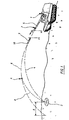
- an artillery 1 such that a self-propelled vessel seeks to reach a target 2 by means of a projectile 3.
- the theoretical ballistic trajectory of the projectile is represented by curve 4.
- a pipe of fire (not shown) integrated into artillery 1 determines in function of the coordinates of target 2 and self-propelled vehicle 1, the elevation and bearing angles that it is necessary to give the tube 5 as well as the propellant charge that it is necessary to use to get the theoretical trajectory 4.
- initial velocity Vo of the projectile at the exit of the tube the weapon will not be the one desired.
- the wind also has an influence on the trajectory of the 5 projectile 3.
- the result for projectile 3 is an actual trajectory 6 which deviates significantly from the theoretical trajectory and which leads to a deviation E at the point of impact on the ground of the projectile.
- the method according to the invention proposes to measure non only the Vo but also at least one other value (V1) of the speed of removal of the projectile 3.
- the second measurement V1 is carried out at a distance of the weapon of the order of 5000 m.
- Velocities measured using a Doppler kinemometer are distances, i.e. velocities along a straight line joining the cinemometer to the projectile.
- the fire control therefore has two real values of speed. It can deduce an approximation of the real trajectory 6 and in particular of the initial speed and the drag coefficient.
- the projectile is an explosive projectile intended to have a trajectory to the ground.
- the fire control may deduct a moment from optimal triggering for the projectile element so that minimize the difference E between the impact on the real ground and the impact at desired soil.
- This trigger instant corresponds to point A shown in figure 1. After point A, the trajectory 8 followed by the projectile brings the target closer 2 impact on the ground of the projectile, thus minimizing the difference E.
- this value is transmitted to the projectile, for example by means of the cinemometer or by separate radio link.
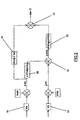
- FIG. 2 shows an example of an algorithm allowing, from two measurements of the speed of separation projectile, to determine the difference that would be observed (without trajectory correction) in the vicinity of the target.
- Step 18 corresponds to the measurement of Vo, the value measured is compared to the Voth (theoretical Vo) which is in memory (firing table).
- the computer deduces a ⁇ Vo which is the difference measured.
- Step 19 corresponds to the measurement of V1. This value measured is compared to a Vlth (theoretical) value which is in memory (other firing table), which allows to deduce the difference on V1, noted ⁇ V1.
- the difference measured on V1 partly corresponds to the difference observed on the Vo and partly to the influence of the drag real aerodynamics.
- Another algorithm will then be used to determine the time at which a correction of trajectory to minimize the deviation E.
- the optimal instant will depend on the characteristics of the braking means used, characteristics which will be memorized in the conduct of shoot.
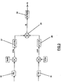
- Figure 3 shows a variant of the algorithm previous in which the measured deviations ⁇ Vo and ⁇ V1 are respectively multiplied by ⁇ o coefficients (block 27) and ⁇ 1 (block 28) which are read in firing tables and which depend on the shooting conditions (angles initial speeds and speeds).
- the forecast difference E is obtained by performing the sum (summator 29) ⁇ o x ⁇ Vo + ⁇ 1 x ⁇ V1.
- the coefficients ⁇ o and ⁇ 1 tables will be determined by calculation (and / or tests).
- This function k depends on the characteristics of the means of braking used.
- the standard deviation observed on impact on the ground is about 560m for a projectile without a device for correction. It is close to 150 m for a projectile with braking means on the trajectory and implemented with the programming method according to the invention.
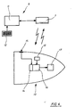
- Figure 4 shows schematically, on the one hand the firing line 9 implementing such a method, and on the other hand the rocket 10 equipping the projectile 3.
- the firing line comprises a computer 11, a programming interface 12 and a Doppler radar kinemometer 7.
- Rocket 10 contains a clock 13, a receiver 14 of programming commands which is connected to an antenna 15, a calculation unit 16 and an element 17 whose triggering is controlled on trajectory and which will cause for example the deployment of braking means. It also contains an energy source (of known type and not shown) such a battery which can be started by firing the projectile.
- an energy source of known type and not shown
- the antenna 15 is produced in the form for example of a plate carrying a printed circuit (or patch) arranged on the rocket wall.
- the computer 11 of the firing line comprises different memories or registers storing the firing tables giving the theoretical values of the speeds Vo and V1 in according to the increases and propellant charges used.
- the firing line 9 After calculating the optimal triggering time of element 17, the firing line 9 transmits to the rocket 10 programming information from the computing unit 16.
- This information may be transmitted by over the air with a radio frequency transmitter (not shown) or be transmitted by the cinemometer 7 using the radar frequency as carrier.
- the rocket antenna 15 receives this information from programming which is eventually decoded and converted to digital signal from receiver 14. Programming is then entered into a memory or register of the unit of calculation 16 which will trigger element 17 at the desired time.
- the rocket will include known means and not shown to determine the firing instant.
- the programming transmitted may correspond to a time interval counted from the moment of firing, or yet counted from another reference time to transmitted by the fire control.
- the rocket calculation unit then contains both information relating to the reference time and a information relating to the duration which must separate the instant from reference and when the element should be triggered 17. It then suffices for him to measure the time (given by the clock 13) which flows from the moment of benchmark, to constantly compare this time with duration programmed and trigger element 17 when the time actually elapsed is equal to the programmed time.
- rocket 10 can receive a pre-programming in the weapon which will give it a instant of triggering of element 17 corresponding to a theoretical deviation E to be corrected, deviation calculated taking into account known shooting conditions.
- the method according to the invention will make it possible to calculate certain real parameters of the shot considered (initial speed real, decrease in speed due to drag real aerodynamics). It will deduce therefrom an estimated difference E and will send the rocket a simple modification of the initial programming to account for the difference between the predicted theoretical deviation E and the estimated deviation E.
- the rocket will then contain the algorithms allowing it to determine the trigger time itself.
- Figure Sa shows by way of example a rocket 10 which has a front part 10a and a rear part 10b.
- the rear part 10b contains the different circuits electronics and in particular the calculation unit 16 connected to antenna 15.
- the front part 10a contains the element 17 which is constituted here by a pyrotechnic charge initiated by a electrical primer.
- Front part 10a and rear part 10b are separated by a circular rupture initiator 24.
- the front part 10a could for example be constituted by a thin envelope in steel which will be fixed by clipping or gluing in a groove carried by the rear part 10b.
- the latter causes initiation of the pyrotechnic charge 17.
- the increase resulting pressure inside the front 10a causes its separation from the rear part 10b.
- Element 17 could then be a micromotor, or a pyrotechnic means, or even a centrifugal device ensuring the deployment of the fins.
- the braking characteristics of these means will also determined and stored in the fire control 9, several types of rockets having braking means different can also be managed by the same pipe shooting.
- the invention can also be applied to a shell whose efficiency does not result from an actual impact on the ground but which releases on trajectory submunitions, guided or not.
- the rocket used will in this case have a function which is to trigger the ejection of the submunitions at a given time.
- timekeeping rockets receive a flight duration programming at the end of which ejection must be ordered, this ejection occurs usually in the last moments of the trajectory, at a time such that the projectile is about 500 to 1000 m altitude above the ground.
- the rocket according to the invention will also command ejection but at a time which will be corrected so as to take into account the trajectory modification which is intervened.
- This new programming of the moment ejection may be transmitted to the rocket by the pipe firing at the same time as the programming of the instant of trajectory correction.
- element 17 will be the charge pyrotechnic ejection of submunitions.
- FIG. 6 shows schematically such an implementation of the process according to the invention.
- the rocket 10 used will implement the method according to the invention.
- the ejection will then take place at point A of the actual trajectory 6, point located before the ejection point theoretical DR.
- the submunitions will then follow paths 8.1, 8.2 and 8.3 which will bring them into the area target 2.
- the fire control will therefore determine, depending on the measured speeds, not the difference between impacts on the ground theoretical and predictable for the projectile itself but the foreseeable difference for the arrivals on the ground of the sub ammunition (i.e. the gap between zones 2 and 31).
- the optimal instant determined by the fire control will be then the one to which the ejection of submunitions must be triggered so that they can treat the area target 2 despite the deviation of the real trajectory from the theoretical trajectory.
Claims (12)
- Verfahren, das die Programmierung eines Auslösezeitpunktes eines Elementes (17) eines Projektils (3) von einer Feuerleitung (9) einer Waffe (1) aus im Flug ermöglicht, wobei in dem Verfahren die Anfangsgeschwindigkeit V0 des Projektils (3) gemessen wird, dann die Geschwindigkeit, mit der sich das Projektil (3) entfernt, an wenigstens einem weiteren Punkt seiner Flugbahn nach dem Austritt aus dem Waffenrohr gemessen wird, wobei das Verfahren dadurch gekennzeichnet ist, dass die Messungen der Anfangsgeschwindigkeit und der Geschwindigkeit, mit der sich das Projektil entfernt, mit Hilfe eines gleichen Geschwindigkeitsmessers bewerkstelligt werden und dass von diesen gemessenen Werten ausgehend ein optimaler Auslösezeitpunkt für das Projektilelement (17) in der Weise bestimmt wird, dass die Abweichung zwischen dem Ist-Aufprall und dem Soll-Aufprall am Boden für das Projektil oder eine Nutzlast, die es auf der Flugbahn freisetzt, minimiert wird, dann wird eine Programmierung oder eine Korrektur der Programmierung, die diesem optimalen Auslösezeitpunkt Rechnung trägt, dem Projektil übermittelt.
- Verfahren nach Anspruch 1, dadurch gekennzeichnet, dass zum Bestimmen des optimalen Auslösezeitpunktes, wird/werden:die Abweichung im Bereich des vorhergesehenen Aufpralls am Boden, der auf die gemessene Veränderung der Anfangsgeschwindigkeit V0 des Projektils zurückzuführen ist, bestimmt wird,daraus auf die vorhergesehene Abweichung im Bereich des Aufpralls am Boden geschlossen, die auf die Veränderung des aerodynamischen Widerstands zurückzuführen ist, indem von einer Messung der Geschwindigkeit des sich Entfernens die Veränderung der Geschwindigkeit des sich Entfernens, die auf die Veränderung der Anfangsgeschwindigkeit zurückzuführen ist, abgezogen wird,die zwei vorhergesehenen so ausgewerteten Abweichungen hinzugefügt.
- Verfahren nach Anspruch 1, dadurch gekennzeichnet, dass zum Bestimmen des optimalen Auslösezeitpunktes wird:die vorhergesehene Abweichung im Bereich des Aufpralls am Boden bestimmt, indem eine lineare Verknüpfung der an wenigsten zwei Punkten gemessenen Geschwindigkeitsabweichung vorgenommen wird.
- Verfahren nach einem der Ansprüche 1 bis 3, dadurch gekennzeichnet, dass:vor dem Abschuss ein theoretischer Auslösezeitpunkt programmiert, der Eigenschaften der gesuchten theoretischen Flugbahn berücksichtigt wird,dem Projektil nach dem Abschuss eine Korrektur der anfänglichen Programmierung übermittelt wird.
- Verfahren nach einem der Ansprüche 1 bis 3, dadurch gekennzeichnet, dass dem Projektil nach dem Abschuss eine Programmierung in Form eines Auslösezeitpunktes übermittelt wird, welcher von einem Referenzzeitpunkt aus zurückgerechnet wurde.
- Verfahren nach einem der Ansprüche 1 bis 5, dadurch gekennzeichnet, dass die Übermittlung zum Projektil in den ersten Augenblicken der Flugbahn des Projektils bewerkstelligt wird, zum Beispiel bei einem Abstand zur Waffe von kleiner oder gleich zehn Kilometern.
- Feuerleitung (9), die das Verfahren nach einem der Ansprüche 1 bis 6 verwendet, dadurch gekennzeichnet, dass sie einen Geschwindigkeitsmesser (7), der die Messung der Anfangsgeschwindigkeit V0 des Projektils (3) sowie die Messung der Geschwindigkeit, mit der sich das Projektil (3) entfernt, an wenigstens einem weiteren Punkt seiner Flugbahn nach dem Verlassen des Waffenrohres, gewährleistet, einen Rechner (11) und Mittel zur Übermittlung umfasst.
- Feuerleitung nach Anspruch 7, dadurch gekennzeichnet, dass der Geschwindigkeitsmesser (7) sich der Radar-Technologie bedient.
- Feuerleitung nach Anspruch 8, dadurch gekennzeichnet, dass die Mittel zur Übermittlung aus dem Radar-Geschwindigkeitsmesser (7) selbst gebildet werden.
- Programmierbarer Zünder (10), der dafür vorgesehen ist, in einem Projektil (3) eingesetzt und durch die Feuerleitung (9) nach der Ansprüche 7 bis 9 programmiert zu werden, wobei der Zünder dadurch gekennzeichnet ist, dass er einen Zeitgeber (13), einen Empfänger (14), eine Recheneinheit (16) und ein Element (17), dessen Auslösung auf der Flugbahn betätigt wird, umfasst.
- Zünder nach Anspruch 10, dadurch gekennzeichnet, dass das auf der Flugbahn ausgelöste Element (17) ein Mittel zum Abbremsen des Projektils, das seinen aerodynamischen Widerstand verändert, ist.
- Zünder nach Anspruch 10, dadurch gekennzeichnet, dass Das auf der Flugbahn ausgelöste Element (17) eine pyrotechnische Ladung zum Ausstoß wenigstens einer Teilmunition ist.
Applications Claiming Priority (2)
| Application Number | Priority Date | Filing Date | Title |
|---|---|---|---|
| FR9704051 | 1997-04-03 | ||
| FR9704051A FR2761767B1 (fr) | 1997-04-03 | 1997-04-03 | Procede de programmation en vol d'un instant de declenchement d'un element de projectile, conduite de tir et fusee mettant en oeuvre un tel procede |
Publications (3)
| Publication Number | Publication Date |
|---|---|
| EP0887613A2 EP0887613A2 (de) | 1998-12-30 |
| EP0887613A3 EP0887613A3 (de) | 1999-01-20 |
| EP0887613B1 true EP0887613B1 (de) | 2003-08-20 |
Family
ID=9505465
Family Applications (1)
| Application Number | Title | Priority Date | Filing Date |
|---|---|---|---|
| EP98104650A Expired - Lifetime EP0887613B1 (de) | 1997-04-03 | 1998-03-14 | Im-Flug-Programmierverfahren für Auslösungsmoment eines Geschosselements, Feuerleitung und Zünder zur Durchführung dieses Verfahrens |
Country Status (5)
| Country | Link |
|---|---|
| US (1) | US6216595B1 (de) |
| EP (1) | EP0887613B1 (de) |
| DE (1) | DE69817267T2 (de) |
| DK (1) | DK0887613T3 (de) |
| FR (1) | FR2761767B1 (de) |
Cited By (1)
| Publication number | Priority date | Publication date | Assignee | Title |
|---|---|---|---|---|
| WO2021066698A1 (en) | 2019-09-30 | 2021-04-08 | Bae Systems Bofors Ab | Method, computer program and weapons system for calculating a bursting point of a projectile |
Families Citing this family (37)
| Publication number | Priority date | Publication date | Assignee | Title |
|---|---|---|---|---|
| ES2185285T3 (es) * | 1998-10-08 | 2003-04-16 | Contraves Pyrotec Ag | Procedimiento para corregir una activacion previamente programada de un proceso en un proyectil estabilizado por rotacion, dispositivo para la realizacion del procedimiento y utilizacion del dispositivo. |
| US6349652B1 (en) * | 2001-01-29 | 2002-02-26 | The United States Of America As Represented By The Secretary Of The Army | Aeroballistic diagnostic system |
| FR2847034B1 (fr) * | 2002-11-08 | 2007-03-02 | Giat Ind Sa | Procede de correction de la trajectoire d'un projectile gyrostabilise et projectile mettant en oeuvre un tel procede |
| US7121210B2 (en) * | 2003-02-18 | 2006-10-17 | Kdi Precision Products, Inc. | Accuracy fuze for airburst cargo delivery projectiles |
| ES2301750T3 (es) * | 2003-02-26 | 2008-07-01 | Rwm Schweiz Ag | Procedimiento para programar la fragmentacion de proyectiles y armas de cañon con sistema de programacion. |
| US7530315B2 (en) | 2003-05-08 | 2009-05-12 | Lone Star Ip Holdings, Lp | Weapon and weapon system employing the same |
| US8661980B1 (en) | 2003-05-08 | 2014-03-04 | Lone Star Ip Holdings, Lp | Weapon and weapon system employing the same |
| US6892644B2 (en) * | 2003-08-12 | 2005-05-17 | Omnitek Partners Llc | Projectile having a casing and/or interior acting as a communication bus between electronic components |
| US20050163151A1 (en) * | 2003-08-12 | 2005-07-28 | Omnitek Partners Llc | Projectile having a casing and/or interior acting as a communication bus between electronic components |
| US7249730B1 (en) | 2004-09-23 | 2007-07-31 | United States Of America As Represented By The Secretary Of The Army | System and method for in-flight trajectory path synthesis using the time sampled output of onboard sensors |
| DE102005024179A1 (de) * | 2005-05-23 | 2006-11-30 | Oerlikon Contraves Ag | Verfahren und Vorrichtung zur Tempierung und/oder Korrektur des Zündzeitpunktes eines Geschosses |
| US7352319B2 (en) * | 2005-06-10 | 2008-04-01 | Honeywell International Inc. | Methods and systems utilizing Doppler prediction to enable fusing |
| FR2889300B1 (fr) * | 2005-07-29 | 2007-10-12 | Tda Armements Sas Soc Par Acti | Procede pour determiner la valeur reelle des parametres conditionnant la trajectoire balistique suivie par un projectile |
| US7895946B2 (en) | 2005-09-30 | 2011-03-01 | Lone Star Ip Holdings, Lp | Small smart weapon and weapon system employing the same |
| US7690304B2 (en) | 2005-09-30 | 2010-04-06 | Lone Star Ip Holdings, Lp | Small smart weapon and weapon system employing the same |
| US7591225B1 (en) * | 2005-10-27 | 2009-09-22 | The United States Of America As Represented By The Secretary Of The Navy | Fuze module |
| US7698983B1 (en) * | 2005-11-04 | 2010-04-20 | The United States Of America As Represented By The Secretary Of The Army | Reconfigurable fire control apparatus and method |
| FR2899679A1 (fr) * | 2006-04-07 | 2007-10-12 | Tda Armements Sas Soc Par Acti | Dispositif de controle de mise a feu de la charge d'une roquette et procede de lancement d'une roquette equipe d'un tel dispositif. |
| US7652615B2 (en) * | 2006-05-26 | 2010-01-26 | Thomas Steven H | Methods and systems providing an adaptive threshold for a beam sharpened pulse radar |
| US8541724B2 (en) | 2006-09-29 | 2013-09-24 | Lone Star Ip Holdings, Lp | Small smart weapon and weapon system employing the same |
| US8117955B2 (en) | 2006-10-26 | 2012-02-21 | Lone Star Ip Holdings, Lp | Weapon interface system and delivery platform employing the same |
| US7926402B2 (en) * | 2006-11-29 | 2011-04-19 | Alliant Techsystems Inc. | Method and apparatus for munition timing and munitions incorporating same |
| AU2008343985B2 (en) | 2007-09-21 | 2014-04-17 | Rheinmetall Waffe Munition Gmbh | Method and apparatus for optically programming a projectile |
| SG155076A1 (en) | 2008-02-18 | 2009-09-30 | Advanced Material Engineering | In-flight programming of trigger time of a projectile |
| DE102009011447B9 (de) * | 2009-03-03 | 2012-08-16 | Diehl Bgt Defence Gmbh & Co. Kg | Verfahren zum Zünden eines Gefechtskopfs einer Granate und Fahrzeug |
| GB2479211B (en) * | 2010-03-31 | 2014-07-23 | Qinetiq Ltd | System for the detection of incoming munitions |
| US11047663B1 (en) * | 2010-11-10 | 2021-06-29 | True Velocity Ip Holdings, Llc | Method of coding polymer ammunition cartridges |
| US8935958B2 (en) * | 2010-11-22 | 2015-01-20 | Drs Technologies Canada, Ltd. | Muzzle velocity sensor |
| DE102011018248B3 (de) * | 2011-04-19 | 2012-03-29 | Rheinmetall Air Defence Ag | Vorrichtung und Verfahren zur Programmierung eines Geschosses |
| US9068803B2 (en) | 2011-04-19 | 2015-06-30 | Lone Star Ip Holdings, Lp | Weapon and weapon system employing the same |
| US10514234B2 (en) | 2013-03-27 | 2019-12-24 | Nostromo Holdings, Llc | Method and apparatus for improving the aim of a weapon station, firing a point-detonating or an air-burst projectile |
| US11933585B2 (en) | 2013-03-27 | 2024-03-19 | Nostromo Holdings, Llc | Method and apparatus for improving the aim of a weapon station, firing a point-detonating or an air-burst projectile |
| FR3035205B1 (fr) * | 2015-04-20 | 2018-10-05 | Roxel France | Dispositif de correction de trajectoire d'un projectile et procede de correction de trajectoire |
| US10222188B2 (en) * | 2016-01-15 | 2019-03-05 | Joshua M. Kunz | Projectile with enhanced ballistic efficiency |
| DE102018129786B4 (de) * | 2018-11-26 | 2022-03-03 | Rheinmetall Waffe Munition Gmbh | Erprobungs- und/oder Übungsmunition |
| US10883809B1 (en) * | 2019-05-07 | 2021-01-05 | U.S. Government As Represented By The Secretary Of The Army | Muzzle velocity correction |
| DE102022124558A1 (de) | 2022-09-23 | 2024-03-28 | Rheinmetall Waffe Munition Gmbh | Modulares Zündsystem sowie Munition umfassend ein modulares Zündsystem |
Family Cites Families (13)
| Publication number | Priority date | Publication date | Assignee | Title |
|---|---|---|---|---|
| US3995792A (en) * | 1974-10-15 | 1976-12-07 | The United States Of America As Represented By The Secretary Of The Army | Laser missile guidance system |
| US4237789A (en) * | 1978-09-28 | 1980-12-09 | Motorola, Inc. | Programmable fuze for projectiles |
| US4283989A (en) * | 1979-07-31 | 1981-08-18 | Ares, Inc. | Doppler-type projectile velocity measurement and communication apparatus, and method |
| CA1242516A (en) * | 1982-04-21 | 1988-09-27 | William H. Bell | Terminally guided weapon delivery system |
| SE445952B (sv) * | 1983-03-25 | 1986-07-28 | Bofors Ab | Anordning for att minska projektilspridning |
| US4837718A (en) * | 1987-02-05 | 1989-06-06 | Lear Siegler, Inc. | Doppler radar method and apparatus for measuring a projectile's muzzle velocity |
| US5102065A (en) * | 1988-02-17 | 1992-04-07 | Thomson - Csf | System to correct the trajectory of a projectile |
| US5440990A (en) * | 1993-09-16 | 1995-08-15 | The Walt Disney Company | Electronic time fuze |
| US5647558A (en) * | 1995-02-14 | 1997-07-15 | Bofors Ab | Method and apparatus for radial thrust trajectory correction of a ballistic projectile |
| DE59608912D1 (de) * | 1995-09-28 | 2002-04-25 | Contraves Pyrotec Ag | Verfahren und Vorrichtung zum Programmieren von Zeitzündern von Geschossen |
| NO311953B1 (no) * | 1996-04-19 | 2002-02-18 | Contraves Ag | Fremgangsmåte og innretning for å bestemme et programmerbart prosjektils oppdelingstidspunkt |
| NO311954B1 (no) * | 1996-04-19 | 2002-02-18 | Contraves Ag | Fremgangsmåte for å bestemme et programmerbart prosjektils oppdelingstidspunkt |
| NO312143B1 (no) * | 1996-04-19 | 2002-03-25 | Contraves Ag | Fremgangsmåte for å bestemme önsket oppdelingstidspunkt, s¶rlig for et programmerbart prosjektil |
-
1997
- 1997-04-03 FR FR9704051A patent/FR2761767B1/fr not_active Expired - Lifetime
-
1998
- 1998-03-14 EP EP98104650A patent/EP0887613B1/de not_active Expired - Lifetime
- 1998-03-14 DE DE69817267T patent/DE69817267T2/de not_active Expired - Lifetime
- 1998-03-14 DK DK98104650T patent/DK0887613T3/da active
- 1998-04-03 US US09/054,520 patent/US6216595B1/en not_active Expired - Lifetime
Cited By (2)
| Publication number | Priority date | Publication date | Assignee | Title |
|---|---|---|---|---|
| WO2021066698A1 (en) | 2019-09-30 | 2021-04-08 | Bae Systems Bofors Ab | Method, computer program and weapons system for calculating a bursting point of a projectile |
| US11940249B2 (en) | 2019-09-30 | 2024-03-26 | Bae Systems Bofors Ab | Method, computer program and weapons system for calculating a bursting point of a projectile |
Also Published As
| Publication number | Publication date |
|---|---|
| FR2761767B1 (fr) | 1999-05-14 |
| FR2761767A1 (fr) | 1998-10-09 |
| EP0887613A3 (de) | 1999-01-20 |
| DE69817267T2 (de) | 2004-04-08 |
| EP0887613A2 (de) | 1998-12-30 |
| DE69817267D1 (de) | 2003-09-25 |
| US6216595B1 (en) | 2001-04-17 |
| DK0887613T3 (da) | 2003-12-08 |
Similar Documents
| Publication | Publication Date | Title |
|---|---|---|
| EP0887613B1 (de) | Im-Flug-Programmierverfahren für Auslösungsmoment eines Geschosselements, Feuerleitung und Zünder zur Durchführung dieses Verfahrens | |
| EP0028966B1 (de) | Verfahren zur Endphasenlenkung und -führung von Flugkörpern | |
| FR2704639A1 (fr) | Système de réglage de fusée électronique pour une munition de canon. | |
| EP0273787B1 (de) | Geschoss zum indirekten Angriff auf Panzerfahrzeuge | |
| EP1719969B1 (de) | Verfahren zum Steuern einer Munition oder einer Submunition, Angreifsystem, Munition und Zielanzeiger für eine Durchführung eines solchen Verfahrens | |
| FR2768500A1 (fr) | Procede de guidage autonome d'un projectile d'artillerie stabilise par rotation et projectile d'artillerie guide de facon autonome pour la mise en oeuvre du procede | |
| FR2517818A1 (fr) | Methode de guidage terminal et missile guide operant selon cette methode | |
| EP2009387A1 (de) | Steuerverfahren zur Auslösung eines Angriffsmoduls und Vorrichtung zur Umsetzung eines solchen Verfahrens | |
| EP0800054B1 (de) | Geschoss dessen Sprengladung durch einen Zielanzeiger ausgelöst wird | |
| EP2187163A1 (de) | Programmierungsverfahren einer Rakete mit Geschoss und Programmiervorrichtung, die die Umsetzung eines solchen Verfahrens erlaubt | |
| FR2742540A1 (fr) | Projectile avec un dispositif de correction de la trajectoire | |
| FR2563000A1 (fr) | Systeme d'arme et missile pour la destruction structurale d'une cible aerienne au moyen d'une charge focalisee | |
| FR2695992A1 (fr) | Sous munition à effet dirigé. | |
| EP0918205B1 (de) | Projektil mit radialer Wirkrichtung | |
| FR2792399A1 (fr) | Procede de lancement d'un projectile a portee variable, munition et lanceur associes a un tel projectile | |
| EP2600097B1 (de) | Kontrollverfahren zur Auslösung eines Gefechtskopfes, Kontrollvorrichtung und Zünder eines Geschosses, in dem ein solches Verfahren zur Anwendung kommt | |
| EP1293751B1 (de) | Verfahren zum Einstellen eines Geschosszünders, Programmiereinrichtung und Zeitzünder die in einen solchem Verfahren verwendet werden | |
| EP0913662B1 (de) | Hohlladungsprojektil und dazugehöriges Waffensystem | |
| FR2577036A1 (fr) | Systeme d'arme a projectiles contenant une charge vulnerante | |
| EP0624805A1 (de) | Verfahren zur Verbesserung des Richtens einer Waffe mittels Vorläufergranaten und derartige Granate | |
| EP0420760B1 (de) | Selbstlenkungssystem und -verfahren einer getriebenen ballistischen Luftfahrzeuggeschosses gegen ein Ziel | |
| EP1782018A1 (de) | Verfahren und system zur aktivierung einer munitionslast, mit einer hochpräzisen aktivierungsvorrichtung versehene munition und system zur neutralisierung eines ziels | |
| FR2646903A1 (fr) | Dispositif de mise a feu pour tete de combat a double charge creuse | |
| EP2175226B1 (de) | Steuerungsverfahren eines Angriffsmoduls und Angriffsmodul zur Umsetzung eines solchen Verfahrens | |
| WO2016169760A1 (fr) | Dispositif de correction de trajectoire d'un projectile et procede de correction de trajectoire |
Legal Events
| Date | Code | Title | Description |
|---|---|---|---|
| PUAI | Public reference made under article 153(3) epc to a published international application that has entered the european phase |
Free format text: ORIGINAL CODE: 0009012 |
|
| PUAL | Search report despatched |
Free format text: ORIGINAL CODE: 0009013 |
|
| AK | Designated contracting states |
Kind code of ref document: A2 Designated state(s): DE DK GB NL SE |
|
| AX | Request for extension of the european patent |
Free format text: AL;LT;LV;MK;RO;SI |
|
| AK | Designated contracting states |
Kind code of ref document: A3 Designated state(s): AT BE CH DE DK ES FI FR GB GR IE IT LI LU MC NL PT SE |
|
| AX | Request for extension of the european patent |
Free format text: AL;LT;LV;MK;RO;SI |
|
| K1C3 | Correction of patent application (complete document) published |
Effective date: 19981230 |
|
| 17P | Request for examination filed |
Effective date: 19990623 |
|
| AKX | Designation fees paid |
Free format text: DE DK GB NL SE |
|
| 17Q | First examination report despatched |
Effective date: 20020402 |
|
| GRAH | Despatch of communication of intention to grant a patent |
Free format text: ORIGINAL CODE: EPIDOS IGRA |
|
| GRAH | Despatch of communication of intention to grant a patent |
Free format text: ORIGINAL CODE: EPIDOS IGRA |
|
| GRAA | (expected) grant |
Free format text: ORIGINAL CODE: 0009210 |
|
| AK | Designated contracting states |
Designated state(s): DE DK GB NL SE |
|
| REG | Reference to a national code |
Ref country code: GB Ref legal event code: FG4D Free format text: NOT ENGLISH |
|
| REF | Corresponds to: |
Ref document number: 69817267 Country of ref document: DE Date of ref document: 20030925 Kind code of ref document: P |
|
| GBT | Gb: translation of ep patent filed (gb section 77(6)(a)/1977) | ||
| REG | Reference to a national code |
Ref country code: SE Ref legal event code: TRGR |
|
| REG | Reference to a national code |
Ref country code: DK Ref legal event code: T3 |
|
| PLBE | No opposition filed within time limit |
Free format text: ORIGINAL CODE: 0009261 |
|
| STAA | Information on the status of an ep patent application or granted ep patent |
Free format text: STATUS: NO OPPOSITION FILED WITHIN TIME LIMIT |
|
| 26N | No opposition filed |
Effective date: 20040524 |
|
| REG | Reference to a national code |
Ref country code: GB Ref legal event code: 732E Free format text: REGISTERED BETWEEN 20090625 AND 20090701 |
|
| REG | Reference to a national code |
Ref country code: NL Ref legal event code: SD Effective date: 20150323 |
|
| PGFP | Annual fee paid to national office [announced via postgrant information from national office to epo] |
Ref country code: SE Payment date: 20170224 Year of fee payment: 20 Ref country code: DE Payment date: 20170222 Year of fee payment: 20 |
|
| PGFP | Annual fee paid to national office [announced via postgrant information from national office to epo] |
Ref country code: GB Payment date: 20170224 Year of fee payment: 20 Ref country code: NL Payment date: 20170221 Year of fee payment: 20 Ref country code: DK Payment date: 20170222 Year of fee payment: 20 |
|
| REG | Reference to a national code |
Ref country code: DE Ref legal event code: R071 Ref document number: 69817267 Country of ref document: DE Ref country code: NL Ref legal event code: MK Effective date: 20180313 |
|
| REG | Reference to a national code |
Ref country code: DK Ref legal event code: EUP Effective date: 20180314 |
|
| REG | Reference to a national code |
Ref country code: GB Ref legal event code: PE20 Expiry date: 20180313 |
|
| PG25 | Lapsed in a contracting state [announced via postgrant information from national office to epo] |
Ref country code: GB Free format text: LAPSE BECAUSE OF EXPIRATION OF PROTECTION Effective date: 20180313 |
|
| REG | Reference to a national code |
Ref country code: SE Ref legal event code: EUG |