EP0887613B1 - In-flight programming method of the triggering moment of a projectile element, firing control and fuse for carrying out this method - Google Patents
In-flight programming method of the triggering moment of a projectile element, firing control and fuse for carrying out this method Download PDFInfo
- Publication number
- EP0887613B1 EP0887613B1 EP98104650A EP98104650A EP0887613B1 EP 0887613 B1 EP0887613 B1 EP 0887613B1 EP 98104650 A EP98104650 A EP 98104650A EP 98104650 A EP98104650 A EP 98104650A EP 0887613 B1 EP0887613 B1 EP 0887613B1
- Authority
- EP
- European Patent Office
- Prior art keywords
- projectile
- trajectory
- velocity
- programming
- fire control
- Prior art date
- Legal status (The legal status is an assumption and is not a legal conclusion. Google has not performed a legal analysis and makes no representation as to the accuracy of the status listed.)
- Expired - Lifetime
Links
- 238000010304 firing Methods 0.000 title claims description 33
- 238000000034 method Methods 0.000 title claims description 33
- 238000005259 measurement Methods 0.000 claims description 22
- 238000012937 correction Methods 0.000 claims description 20
- 230000008569 process Effects 0.000 claims description 14
- 230000005540 biological transmission Effects 0.000 claims description 8
- 230000001960 triggered effect Effects 0.000 claims description 7
- 238000005516 engineering process Methods 0.000 claims description 2
- 238000004422 calculation algorithm Methods 0.000 description 12
- 238000004364 calculation method Methods 0.000 description 9
- 230000006870 function Effects 0.000 description 9
- 230000004048 modification Effects 0.000 description 7
- 238000012986 modification Methods 0.000 description 7
- 230000008901 benefit Effects 0.000 description 5
- 230000015654 memory Effects 0.000 description 4
- 235000015842 Hesperis Nutrition 0.000 description 3
- 235000012633 Iberis amara Nutrition 0.000 description 3
- 238000010586 diagram Methods 0.000 description 3
- 239000006185 dispersion Substances 0.000 description 3
- 239000000843 powder Substances 0.000 description 3
- 238000000926 separation method Methods 0.000 description 3
- 239000002360 explosive Substances 0.000 description 2
- 239000003380 propellant Substances 0.000 description 2
- 239000002689 soil Substances 0.000 description 2
- 238000012360 testing method Methods 0.000 description 2
- 229910000831 Steel Inorganic materials 0.000 description 1
- 230000009471 action Effects 0.000 description 1
- 238000004026 adhesive bonding Methods 0.000 description 1
- 230000000694 effects Effects 0.000 description 1
- 239000003999 initiator Substances 0.000 description 1
- 230000000977 initiatory effect Effects 0.000 description 1
- 230000007246 mechanism Effects 0.000 description 1
- 230000035945 sensitivity Effects 0.000 description 1
- 239000010959 steel Substances 0.000 description 1
Images


Classifications
-
- F—MECHANICAL ENGINEERING; LIGHTING; HEATING; WEAPONS; BLASTING
- F41—WEAPONS
- F41G—WEAPON SIGHTS; AIMING
- F41G7/00—Direction control systems for self-propelled missiles
- F41G7/20—Direction control systems for self-propelled missiles based on continuous observation of target position
- F41G7/30—Command link guidance systems
-
- F—MECHANICAL ENGINEERING; LIGHTING; HEATING; WEAPONS; BLASTING
- F42—AMMUNITION; BLASTING
- F42C—AMMUNITION FUZES; ARMING OR SAFETY MEANS THEREFOR
- F42C11/00—Electric fuzes
- F42C11/06—Electric fuzes with time delay by electric circuitry
- F42C11/065—Programmable electronic delay initiators in projectiles
-
- F—MECHANICAL ENGINEERING; LIGHTING; HEATING; WEAPONS; BLASTING
- F42—AMMUNITION; BLASTING
- F42C—AMMUNITION FUZES; ARMING OR SAFETY MEANS THEREFOR
- F42C17/00—Fuze-setting apparatus
- F42C17/04—Fuze-setting apparatus for electric fuzes
-
- G—PHYSICS
- G01—MEASURING; TESTING
- G01P—MEASURING LINEAR OR ANGULAR SPEED, ACCELERATION, DECELERATION, OR SHOCK; INDICATING PRESENCE, ABSENCE, OR DIRECTION, OF MOVEMENT
- G01P3/00—Measuring linear or angular speed; Measuring differences of linear or angular speeds
- G01P3/64—Devices characterised by the determination of the time taken to traverse a fixed distance
- G01P3/66—Devices characterised by the determination of the time taken to traverse a fixed distance using electric or magnetic means
- G01P3/665—Devices characterised by the determination of the time taken to traverse a fixed distance using electric or magnetic means for projectile velocity measurements
Definitions
- the technical field of the invention is that of processes allowing the programming in flight of an instant of firing of a projectile element from a fire control of a weapon.
- the patent US3995792 thus describes a projectile whose actual trajectory is measured with tracking means laser.
- a fire line calculates from this measurement the difference between the actual trajectory and the trajectory theoretical and transmits correction orders to the projectile allowing to approximate the real trajectory of the theoretical trajectory.
- the trajectory correction is for example obtained at by means of impellers or control surfaces.
- Such tracking means are also bulky and delicate implementation.
- laser tracking of a large part of the trajectory of the projectile harms the discretion of the shot and may facilitate the location of artillery by the opposing forces.
- the projectile receives a program before firing which gives its theoretical trajectory and its point of impact on the ground wish. He himself measures his real trajectory and, at the by means of appropriate algorithms, commands the implementation of trajectory correction means.
- Such a projectile is very expensive because it incorporates a electronics associated with a self-location device by satellites.
- the auto-location system is bulky and harms the carrying capacity of the projectile.
- WO84 / 03759 describes a device for reduce the dispersion of artillery fire. These measures implements a cinemometer, a radar for tracking the projectile and radio transmission means.
- the radar ensures the continuation of the entire trajectory of the projectile and another radar monitors the position of the target.
- the firing line sends to the projectile at an instant issued a trajectory correction order for the get closer to its target.
- Such a device is costly to implement since two radars are mobilized: one for target tracking, the other for that of the projectile. Discretion is not no more assured since the correction order is sent to trajectory very far from the shooting platform.
- WO96 / 25641 describes a correction method of a trajectory of a ballistic projectile by impellers at radial action.
- This correction method implements a fire control connected to a fire control radar allowing to continue the projectile to determine its real trajectory, and to a speed measurement system initial of the projectile.
- Such a device is also complex implementation.
- the method according to the invention makes it possible to improve notably the accuracy of the shot while not requiring expensive equipment.
- the invention also relates to a rocket intended for equip a projectile and receive programming transmitted by the method according to the invention.
- This simple and inexpensive rocket can be adapted to any type of projectile and thus allows in a simple way improve the shooting accuracy of conventional projectiles already in stock in the armed forces.
- the subject of the invention is a method of programming in flight an instant of triggering of an element of a projectile from a firing pipe of a weapon, method in which the initial speed Vo of the projectile, then the velocity of removal of the projectile is measured at at least one other point on its trajectory after the exit from the barrel of the weapon, a process characterized in that the measurements of initial velocity and of velocity of removal are carried out at using the same kinemometer and by determining from these measured values an optimal triggering moment for the projectile element so as to minimize the difference between the impact on the real ground and the impact on the ground desired for the projectile or a payload that it releases on trajectory, then a programming or a programming correction is transmitted to the projectile taking into account this optimal triggering instant.
- the transmission to the projectile will be performed in the first moments of the trajectory of the projectile, for example at a distance from the lower weapon or equal to ten kilometers.
- the invention also relates to a firing line implementing such a method, fire control characterized in that it comprises a cinemometer ensuring the measurement of the initial velocity Vo of the projectile, as well as the measurement of the projectile's removal speed in at minus another point on its trajectory after leaving the weapon barrel, calculator and transmission means.
- the cinemometer will advantageously be of radar technology.
- the means of transmission which can be constituted by the radar radar meter itself.
- the invention finally relates to a programmable rocket intended to be placed on a projectile and to be programmed by such a fire control, characterized rocket in that it includes a clock, a receiver, a unit of calculation and an element whose triggering is controlled on trajectory.
- the element triggered on trajectory could be a means braking the projectile modifying its aerodynamic drag, or a pyrotechnic ejection charge of at least one submunition.
- One of the advantages of the invention is that it allows a rapid acquisition of an estimated projectile trajectory with simple and inexpensive means.
- Another advantage of the invention is that it promotes the discretion of the shot, the distance velocity measurements being few (one to three), carried out punctually and not continuously and at a short distance from the weapon.
- Another advantage is that the rocket programming intervenes at a reduced distance from the weapon which improves the reliability of the programming and reduces its sensitivity to interference.
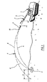
- an artillery 1 such that a self-propelled vessel seeks to reach a target 2 by means of a projectile 3.
- the theoretical ballistic trajectory of the projectile is represented by curve 4.
- a pipe of fire (not shown) integrated into artillery 1 determines in function of the coordinates of target 2 and self-propelled vehicle 1, the elevation and bearing angles that it is necessary to give the tube 5 as well as the propellant charge that it is necessary to use to get the theoretical trajectory 4.
- initial velocity Vo of the projectile at the exit of the tube the weapon will not be the one desired.
- the wind also has an influence on the trajectory of the 5 projectile 3.
- the result for projectile 3 is an actual trajectory 6 which deviates significantly from the theoretical trajectory and which leads to a deviation E at the point of impact on the ground of the projectile.
- the method according to the invention proposes to measure non only the Vo but also at least one other value (V1) of the speed of removal of the projectile 3.
- the second measurement V1 is carried out at a distance of the weapon of the order of 5000 m.
- Velocities measured using a Doppler kinemometer are distances, i.e. velocities along a straight line joining the cinemometer to the projectile.
- the fire control therefore has two real values of speed. It can deduce an approximation of the real trajectory 6 and in particular of the initial speed and the drag coefficient.
- the projectile is an explosive projectile intended to have a trajectory to the ground.
- the fire control may deduct a moment from optimal triggering for the projectile element so that minimize the difference E between the impact on the real ground and the impact at desired soil.
- This trigger instant corresponds to point A shown in figure 1. After point A, the trajectory 8 followed by the projectile brings the target closer 2 impact on the ground of the projectile, thus minimizing the difference E.
- this value is transmitted to the projectile, for example by means of the cinemometer or by separate radio link.
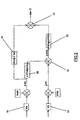
- FIG. 2 shows an example of an algorithm allowing, from two measurements of the speed of separation projectile, to determine the difference that would be observed (without trajectory correction) in the vicinity of the target.
- Step 18 corresponds to the measurement of Vo, the value measured is compared to the Voth (theoretical Vo) which is in memory (firing table).
- the computer deduces a ⁇ Vo which is the difference measured.
- Step 19 corresponds to the measurement of V1. This value measured is compared to a Vlth (theoretical) value which is in memory (other firing table), which allows to deduce the difference on V1, noted ⁇ V1.
- the difference measured on V1 partly corresponds to the difference observed on the Vo and partly to the influence of the drag real aerodynamics.
- Another algorithm will then be used to determine the time at which a correction of trajectory to minimize the deviation E.
- the optimal instant will depend on the characteristics of the braking means used, characteristics which will be memorized in the conduct of shoot.
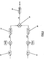
- Figure 3 shows a variant of the algorithm previous in which the measured deviations ⁇ Vo and ⁇ V1 are respectively multiplied by ⁇ o coefficients (block 27) and ⁇ 1 (block 28) which are read in firing tables and which depend on the shooting conditions (angles initial speeds and speeds).
- the forecast difference E is obtained by performing the sum (summator 29) ⁇ o x ⁇ Vo + ⁇ 1 x ⁇ V1.
- the coefficients ⁇ o and ⁇ 1 tables will be determined by calculation (and / or tests).
- This function k depends on the characteristics of the means of braking used.
- the standard deviation observed on impact on the ground is about 560m for a projectile without a device for correction. It is close to 150 m for a projectile with braking means on the trajectory and implemented with the programming method according to the invention.
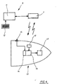
- Figure 4 shows schematically, on the one hand the firing line 9 implementing such a method, and on the other hand the rocket 10 equipping the projectile 3.
- the firing line comprises a computer 11, a programming interface 12 and a Doppler radar kinemometer 7.
- Rocket 10 contains a clock 13, a receiver 14 of programming commands which is connected to an antenna 15, a calculation unit 16 and an element 17 whose triggering is controlled on trajectory and which will cause for example the deployment of braking means. It also contains an energy source (of known type and not shown) such a battery which can be started by firing the projectile.
- an energy source of known type and not shown
- the antenna 15 is produced in the form for example of a plate carrying a printed circuit (or patch) arranged on the rocket wall.
- the computer 11 of the firing line comprises different memories or registers storing the firing tables giving the theoretical values of the speeds Vo and V1 in according to the increases and propellant charges used.
- the firing line 9 After calculating the optimal triggering time of element 17, the firing line 9 transmits to the rocket 10 programming information from the computing unit 16.
- This information may be transmitted by over the air with a radio frequency transmitter (not shown) or be transmitted by the cinemometer 7 using the radar frequency as carrier.
- the rocket antenna 15 receives this information from programming which is eventually decoded and converted to digital signal from receiver 14. Programming is then entered into a memory or register of the unit of calculation 16 which will trigger element 17 at the desired time.
- the rocket will include known means and not shown to determine the firing instant.
- the programming transmitted may correspond to a time interval counted from the moment of firing, or yet counted from another reference time to transmitted by the fire control.
- the rocket calculation unit then contains both information relating to the reference time and a information relating to the duration which must separate the instant from reference and when the element should be triggered 17. It then suffices for him to measure the time (given by the clock 13) which flows from the moment of benchmark, to constantly compare this time with duration programmed and trigger element 17 when the time actually elapsed is equal to the programmed time.
- rocket 10 can receive a pre-programming in the weapon which will give it a instant of triggering of element 17 corresponding to a theoretical deviation E to be corrected, deviation calculated taking into account known shooting conditions.
- the method according to the invention will make it possible to calculate certain real parameters of the shot considered (initial speed real, decrease in speed due to drag real aerodynamics). It will deduce therefrom an estimated difference E and will send the rocket a simple modification of the initial programming to account for the difference between the predicted theoretical deviation E and the estimated deviation E.
- the rocket will then contain the algorithms allowing it to determine the trigger time itself.
- Figure Sa shows by way of example a rocket 10 which has a front part 10a and a rear part 10b.
- the rear part 10b contains the different circuits electronics and in particular the calculation unit 16 connected to antenna 15.
- the front part 10a contains the element 17 which is constituted here by a pyrotechnic charge initiated by a electrical primer.
- Front part 10a and rear part 10b are separated by a circular rupture initiator 24.
- the front part 10a could for example be constituted by a thin envelope in steel which will be fixed by clipping or gluing in a groove carried by the rear part 10b.
- the latter causes initiation of the pyrotechnic charge 17.
- the increase resulting pressure inside the front 10a causes its separation from the rear part 10b.
- Element 17 could then be a micromotor, or a pyrotechnic means, or even a centrifugal device ensuring the deployment of the fins.
- the braking characteristics of these means will also determined and stored in the fire control 9, several types of rockets having braking means different can also be managed by the same pipe shooting.
- the invention can also be applied to a shell whose efficiency does not result from an actual impact on the ground but which releases on trajectory submunitions, guided or not.
- the rocket used will in this case have a function which is to trigger the ejection of the submunitions at a given time.
- timekeeping rockets receive a flight duration programming at the end of which ejection must be ordered, this ejection occurs usually in the last moments of the trajectory, at a time such that the projectile is about 500 to 1000 m altitude above the ground.
- the rocket according to the invention will also command ejection but at a time which will be corrected so as to take into account the trajectory modification which is intervened.
- This new programming of the moment ejection may be transmitted to the rocket by the pipe firing at the same time as the programming of the instant of trajectory correction.
- element 17 will be the charge pyrotechnic ejection of submunitions.
- FIG. 6 shows schematically such an implementation of the process according to the invention.
- the rocket 10 used will implement the method according to the invention.
- the ejection will then take place at point A of the actual trajectory 6, point located before the ejection point theoretical DR.
- the submunitions will then follow paths 8.1, 8.2 and 8.3 which will bring them into the area target 2.
- the fire control will therefore determine, depending on the measured speeds, not the difference between impacts on the ground theoretical and predictable for the projectile itself but the foreseeable difference for the arrivals on the ground of the sub ammunition (i.e. the gap between zones 2 and 31).
- the optimal instant determined by the fire control will be then the one to which the ejection of submunitions must be triggered so that they can treat the area target 2 despite the deviation of the real trajectory from the theoretical trajectory.
Description
Le domaine technique de l'invention est celui des procédés permettant la programmation en vol d'un instant de déclenchement d'un élément de projectile à partir d'une conduite de tir d'une arme.The technical field of the invention is that of processes allowing the programming in flight of an instant of firing of a projectile element from a fire control of a weapon.
Les projectiles tirés par canon ont théoriquement une trajectoire balistique bien connue.Cannon-fired projectiles theoretically have a well-known ballistic trajectory.
Cependant certains facteurs externes non reproductibles sont susceptibles d'influer sur la trajectoire.However, certain non-reproducible external factors are likely to influence the trajectory.
On sait ainsi que la vitesse initiale (Vo) du projectile peut varier de quelques pour-cent d'une charge de poudre à une autre en fonction des conditions de tir (température, dispersion des caractéristiques des poudres, usure du tube...). Il en résulte des écarts au niveau de l'impact au sol du projectile qui peuvent être de l'ordre de 1 à 35 km.We thus know that the initial velocity (Vo) of the projectile can vary from a few percent of a powder charge to another depending on the firing conditions (temperature, dispersion of powder characteristics, wear of the tube...). This results in deviations in terms of impact projectile ground which can be of the order of 1 to 35 km.
Les conditions atmosphériques ainsi que les écarts concernant le coefficient de traínée du projectile influent également notablement sur la trajectoire de celui-ci.Weather conditions and deviations concerning the drag coefficient of the influential projectile also notably on the trajectory of this one.
Afin d'améliorer la précision d'un tir, il est connu de transmettre à un projectile un ordre de correction de trajectoire.In order to improve the accuracy of a shot, it is known to transmitting a correction order to a projectile path.
Le brevet US3995792 décrit ainsi un projectile dont la trajectoire réelle est mesurée avec un moyen de poursuite laser. Une conduite de tir calcule à partir de cette mesure l'écart entre la trajectoire réelle et la trajectoire théorique et transmet au projectile des ordres de correction permettant de rapprocher la trajectoire réelle de la trajectoire théorique.The patent US3995792 thus describes a projectile whose actual trajectory is measured with tracking means laser. A fire line calculates from this measurement the difference between the actual trajectory and the trajectory theoretical and transmits correction orders to the projectile allowing to approximate the real trajectory of the theoretical trajectory.
La correction de trajectoire est par exemple obtenue au moyen d'impulseurs ou de gouvernes.The trajectory correction is for example obtained at by means of impellers or control surfaces.
Un inconvénient d'une telle solution est son coût. En effet la poursuite de la trajectoire du projectile implique la mise en oeuvre de moyens puissants (donc chers) dont la portée dépasse 15 km.A disadvantage of such a solution is its cost. In effect the continuation of the trajectory of the projectile implies the implementation of powerful means (therefore expensive) including the range exceeds 15 km.
De tels moyens de poursuite sont également encombrants et de mise en oeuvre délicate.Such tracking means are also bulky and delicate implementation.
De plus la poursuite par laser d'une grande partie de la trajectoire du projectile nuit à la discrétion du tir et risque de faciliter la localisation de l'artillerie par les forces adverses.In addition, laser tracking of a large part of the trajectory of the projectile harms the discretion of the shot and may facilitate the location of artillery by the opposing forces.
On connaít également un projectile totalement autonome qui se localise lui même au moyen d'un dispositif de positionnement par satellites (GPS).We also know a totally autonomous projectile which locates itself by means of a satellite positioning (GPS).
Le projectile reçoit avant tir une programmation qui lui donne sa trajectoire théorique et son point d'impact au sol souhaité. Il mesure lui même sa trajectoire réelle et, au moyen d'algorithmes appropriés, commande la mise en oeuvre de moyens de correction de trajectoire.The projectile receives a program before firing which gives its theoretical trajectory and its point of impact on the ground wish. He himself measures his real trajectory and, at the by means of appropriate algorithms, commands the implementation of trajectory correction means.
Un tel projectile est très coûteux car il intègre une électronique associée à un dispositif d'auto-localisation par satellites. De plus, le système d'auto-localisation est encombrant et nuit à la capacité d'emport du projectile.Such a projectile is very expensive because it incorporates a electronics associated with a self-location device by satellites. In addition, the auto-location system is bulky and harms the carrying capacity of the projectile.
Le brevet WO84/03759 décrit un dispositif permettant de réduire la dispersion des tirs d'artillerie. Ce dispositif met en oeuvre un cinémomètre, un radar de poursuite du projectile et des moyens de transmission radio.WO84 / 03759 describes a device for reduce the dispersion of artillery fire. These measures implements a cinemometer, a radar for tracking the projectile and radio transmission means.
Le radar assure la poursuite de toute la trajectoire du projectile et un autre radar surveille la position de la cible. La conduite de tir envoie au projectile à un instant donné un ordre de correction de trajectoire pour le rapprocher de sa cible.The radar ensures the continuation of the entire trajectory of the projectile and another radar monitors the position of the target. The firing line sends to the projectile at an instant issued a trajectory correction order for the get closer to its target.
Un tel dispositif est coûteux à mettre en oeuvre puisque deux radars sont mobilisés : un pour la poursuite de cible, l'autre pour celle du projectile. La discrétion n'est pas non plus assurée puisque l'ordre de correction est envoyé sur trajectoire très loin de la plateforme de tir.Such a device is costly to implement since two radars are mobilized: one for target tracking, the other for that of the projectile. Discretion is not no more assured since the correction order is sent to trajectory very far from the shooting platform.
Le document WO96/25641 décrit un procédé de correction d'une trajectoire d'un projectile balistique par impulseurs à action radiale. Ce procédé de correction met en oeuvre une conduite de tir reliée à un radar de contrôle de tir permettant de poursuivre le projectile pour déterminer sa trajectoire réelle, et à un système de mesure de vitesse initiale du projectile. Un tel dispositif est également de mise en oeuvre complexe. WO96 / 25641 describes a correction method of a trajectory of a ballistic projectile by impellers at radial action. This correction method implements a fire control connected to a fire control radar allowing to continue the projectile to determine its real trajectory, and to a speed measurement system initial of the projectile. Such a device is also complex implementation.
C'est le but de l'invention que de proposer un procédé (et une conduite de tir associée) permettant la programmation en vol d'un instant de déclenchement d'un élément de projectile, procédé et conduite de tir ne présentant pas les inconvénients des systèmes connus.It is the object of the invention to propose a method (and an associated fire control) allowing programming in flight from an instant of triggering an element of projectile, method and fire control not having the disadvantages of known systems.
Ainsi le procédé selon l'invention permet d'améliorer notablement la précision du tir tout en ne nécessitant pas d'équipements coûteux.Thus the method according to the invention makes it possible to improve notably the accuracy of the shot while not requiring expensive equipment.
Il ne nuit pas en outre à la discrétion du système d'arme.It also does not harm the discretion of the system weapon.
L'invention a également pour objet une fusée destinée à équiper un projectile et à recevoir la programmation transmise par le procédé selon l'invention.The invention also relates to a rocket intended for equip a projectile and receive programming transmitted by the method according to the invention.
Cette fusée simple et peu coûteuse peut être adaptée à tout type de projectile et permet ainsi d'une façon simple d'améliorer la précision de tir des projectiles conventionnels déjà en stocks dans les forces armées.This simple and inexpensive rocket can be adapted to any type of projectile and thus allows in a simple way improve the shooting accuracy of conventional projectiles already in stock in the armed forces.
Ainsi l'invention a pour objet un procédé de programmation en vol d'un instant de déclenchement d'un élément d'un projectile à partir d'une conduite de tir d'une arme, procédé dans lequel on mesure la vitesse initiale Vo du projectile, puis on mesure la vitesse d'éloignement du projectile en au moins un autre point de sa trajectoire après la sortie du tube de l'arme, procédé caractérisé en ce que les mesures de vitesse initiale et de vitesse d'éloignement sont effectuées à l'aide d'un même cinémomètre et en ce qu'on détermine à partir de ces valeurs mesurées un instant de déclenchement optimal pour l'élément de projectile de façon à minimiser l'écart entre l'impact au sol réel et l'impact au sol souhaité pour le projectile ou une charge utile qu'il libère sur trajectoire, puis on transmet au projectile une programmation ou une correction de la programmation tenant compte de cet instant de déclenchement optimal.Thus, the subject of the invention is a method of programming in flight an instant of triggering of an element of a projectile from a firing pipe of a weapon, method in which the initial speed Vo of the projectile, then the velocity of removal of the projectile is measured at at least one other point on its trajectory after the exit from the barrel of the weapon, a process characterized in that the measurements of initial velocity and of velocity of removal are carried out at using the same kinemometer and by determining from these measured values an optimal triggering moment for the projectile element so as to minimize the difference between the impact on the real ground and the impact on the ground desired for the projectile or a payload that it releases on trajectory, then a programming or a programming correction is transmitted to the projectile taking into account this optimal triggering instant.
Avantageusement, pour déterminer l'instant de déclenchement optimal on pourra :
- déterminer l'écart au niveau de l'impact au sol prévisible qui est imputable à la variation mesurée de vitesse initiale Vo du projectile,
- en déduire l'écart prévisible au niveau de l'impact au 5 sol qui est imputable à la variation de traínée aérodynamique en soustrayant d'une mesure de la vitesse d'éloignement la variation de vitesse d'éloignement imputable à la variation de vitesse initiale,
- ajouter les deux écarts prévisibles ainsi évalués.
- determining the deviation from the foreseeable impact on the ground which is attributable to the measured variation in the initial velocity Vo of the projectile,
- deduce therefrom the foreseeable difference in impact on the ground which is attributable to the variation in aerodynamic drag by subtracting from a measurement of the distance velocity the variation in separation velocity attributable to the variation in initial speed ,
- add the two foreseeable deviations thus evaluated.
Pour déterminer l'instant de déclenchement optimal, on pourra également :
- déterminer l'écart prévisible au niveau de l'impact au sol en effectuant une combinaison linéaire des écarts de vitesse mesurés en au moins deux points.
- determine the foreseeable deviation from the ground impact by performing a linear combination of the speed deviations measured at at least two points.
Suivant une variante, on pourra :
- programmer avant tir un instant de déclenchement théorique tenant compte des caractéristiques de la trajectoire théorique recherchée,
- transmettre au projectile après tir une correction de la programmation initiale.
- program before firing a theoretical trigger instant taking into account the characteristics of the theoretical trajectory sought,
- transmit to the projectile after firing a correction of the initial programming.
Alternativement on pourra transmettre au projectile après tir une programmation sous la forme d'un instant de déclenchement décompté à partir d'un instant de référence.Alternatively we can transmit to the projectile after shooting a programming in the form of a moment of triggered countdown from a reference time.
Dans tous les cas, la transmission au projectile sera effectuée dans les premiers instants de la trajectoire du projectile, par exemple à une distance de l'arme inférieure ou égale à dix kilomètres.In all cases, the transmission to the projectile will be performed in the first moments of the trajectory of the projectile, for example at a distance from the lower weapon or equal to ten kilometers.
L'invention a également pour objet une conduite de tir mettant en oeuvre une tel procédé, conduite de tir caractérisée en ce qu'elle comprend un cinémomètre assurant la mesure de la vitesse initiale Vo du projectile, ainsi que la mesure de la vitesse d'éloignement du projectile en au moins un autre point de sa trajectoire après la sortie du tube de l'arme, un calculateur et des moyens de transmission.The invention also relates to a firing line implementing such a method, fire control characterized in that it comprises a cinemometer ensuring the measurement of the initial velocity Vo of the projectile, as well as the measurement of the projectile's removal speed in at minus another point on its trajectory after leaving the weapon barrel, calculator and transmission means.
Le cinémomètre sera avantageusement de technologie radar. The cinemometer will advantageously be of radar technology.
Les moyens de transmission pouvant être constitués par le cinémomètre radar lui même.The means of transmission which can be constituted by the radar radar meter itself.
L'invention a enfin pour objet une fusée programmable destinée à être mise en place sur un projectile et à être programmée par une telle conduite de tir, fusée caractérisée en ce qu'elle comporte une horloge, un récepteur, une unité de calcul et un élément dont le déclenchement est commandé sur trajectoire.The invention finally relates to a programmable rocket intended to be placed on a projectile and to be programmed by such a fire control, characterized rocket in that it includes a clock, a receiver, a unit of calculation and an element whose triggering is controlled on trajectory.
L'élément déclenché sur trajectoire pourra être un moyen de freinage du projectile modifiant sa traínée aérodynamique, ou encore une charge pyrotechnique d'éjection d'au moins une sous-munition.The element triggered on trajectory could be a means braking the projectile modifying its aerodynamic drag, or a pyrotechnic ejection charge of at least one submunition.
Un des avantages de l'invention est qu'elle permet une acquisition rapide d'une trajectoire estimée du projectile avec des moyens simples et peu coûteux.One of the advantages of the invention is that it allows a rapid acquisition of an estimated projectile trajectory with simple and inexpensive means.
Un autre avantage de l'invention est qu'elle favorise la discrétion du tir, les mesures de vitesse d'éloignement étant peu nombreuses (une à trois), réalisées ponctuellement et non en continu et à faible distance de l'arme.Another advantage of the invention is that it promotes the discretion of the shot, the distance velocity measurements being few (one to three), carried out punctually and not continuously and at a short distance from the weapon.
Un autre avantage est que la programmation de la fusée intervient à une distance réduite de l'arme ce qui améliore la fiabilité de la programmation et réduit sa sensibilité au brouillage.Another advantage is that the rocket programming intervenes at a reduced distance from the weapon which improves the reliability of the programming and reduces its sensitivity to interference.
L'invention sera mieux comprise à la lecture de la description de différents modes de réalisation, description faite en référence aux dessins annexés et dans lesquels :
- la figure 1 représente schématiquement la mise en oeuvre du procédé selon l'invention à partir d'une artillerie,
- la figure 2 schématise un algorithme permettant, à partir de deux mesures de la vitesse d'éloignement du projectile, de déterminer l'écart qui serait observé au voisinage de la cible,
- la figure 3 schématise un autre algorithme permettant de déterminer l'écart,
- la figure 4 est un synoptique représentant la conduite de tir solidaire de l'arme et la fusée portée par le projectile,
- les figures 5a et 5b représentent un mode particulier de réalisation de la fusée, respectivement en position de vol et en position de freinage,
- la figure 6 représente schématiquement une autre mise en oeuvre du procédé selon l'invention à partir d'une artillerie.
- FIG. 1 schematically represents the implementation of the method according to the invention from an artillery,
- FIG. 2 diagrams an algorithm making it possible, from two measurements of the speed of removal of the projectile, to determine the difference which would be observed in the vicinity of the target,
- FIG. 3 diagrams another algorithm making it possible to determine the difference,
- FIG. 4 is a block diagram showing the firing line secured to the weapon and the rocket carried by the projectile,
- FIGS. 5a and 5b represent a particular embodiment of the rocket, respectively in the flight position and in the braking position,
- FIG. 6 schematically represents another implementation of the method according to the invention from an artillery.
En se reportant à la figure 1, une artillerie 1 telle
qu'un automoteur cherche à atteindre une cible 2 au moyen
d'un projectile 3. La trajectoire balistique théorique du
projectile est représentée par la courbe 4. Une conduite de
tir (non représentée) intégrée à l'artillerie 1 détermine en
fonction des coordonnées de la cible 2 et de l'automoteur 1,
les angles de site et de gisement qu'il est nécessaire de
donner au tube 5 ainsi que la charge propulsive qu'il est
nécessaire d'utiliser pour obtenir la trajectoire théorique
4.Referring to Figure 1, an
Compte tenu notamment des dispersions des caractéristiques de la poudre et de celles dues à la température, la vitesse initiale Vo du projectile à la sortie du tube de l'arme ne sera pas celle souhaitée.Taking into account in particular the dispersions of the characteristics powder and those due to temperature, initial velocity Vo of the projectile at the exit of the tube the weapon will not be the one desired.
De plus la résistance (ou traínée aérodynamique) du projectile n'est pas totalement maítrisée (elle dépendra notamment du profil de la ceinture du projectile à la sortie du tube, donc de l'usure de celui-ci).In addition the resistance (or aerodynamic drag) of the projectile is not fully controlled (it will depend including the profile of the projectile belt at the exit of the tube, therefore the wear thereof).
Le vent a également une influence sur la trajectoire du
5 projectile 3.The wind also has an influence on the trajectory of the
5
Il en résulte pour le projectile 3 une trajectoire réelle
6 qui s'écarte notablement de la trajectoire théorique et qui
conduit à un écart E au niveau du point d'impact au sol du
projectile.The result for
Concrètement, on a pu montrer que pour une variation de 1% du Vo on obtenait un écart de 600 m par rapport au point visé à une distance de 35 km de l'artillerie.Concretely, we have been able to show that for a variation of 1% of Vo we got a difference of 600 m from the point aimed at a distance of 35 km from the artillery.
On a également vérifié que les variations du coefficient de traínée aérodynamique du projectile pouvaient atteindre 2% et conduisaient à une erreur de 900 m par rapport au point visé pour une distance de tir de 35 km.We also checked that the variations in the coefficient aerodynamic drag of the projectile could reach 2% and led to an error of 900 m from the point aimed for a shooting distance of 35 km.
Il était connu jusqu'à présent de mesurer le Vo au moyen
d'un cinémomètre 7 par exemple radar, cela afin de tenir
compte de cette mesure pour le tir du projectile suivant.It has hitherto been known to measure Vo using
of a
Le procédé selon l'invention propose de mesurer non
seulement le Vo mais aussi au moins une autre valeur (V1) de
la vitesse d'éloignement du projectile 3.The method according to the invention proposes to measure non
only the Vo but also at least one other value (V1) of
the speed of removal of the
La deuxième mesure V1 est effectuée à une distance de l'arme de l'ordre de 5000 m.The second measurement V1 is carried out at a distance of the weapon of the order of 5000 m.
Les vitesses mesurées au moyen d'un cinémomètre Doppler sont des vitesses d'éloignement, c'est à dire des vitesses le long d'une droite joignant le cinémomètre au projectile.Velocities measured using a Doppler kinemometer are distances, i.e. velocities along a straight line joining the cinemometer to the projectile.
La conduite de tir dispose donc de deux valeurs réelles
de la vitesse. Elle peut en déduire une approximation de la
trajectoire réelle 6 et notamment de la vitesse initiale et
du coefficient de traínée.The fire control therefore has two real values
of speed. It can deduce an approximation of the
Dans un premier mode particulier de réalisation, le projectile est un projectile explosif destiné à avoir une trajectoire jusqu'au sol.In a first particular embodiment, the projectile is an explosive projectile intended to have a trajectory to the ground.
Afin qu'il puisse parvenir au sol au niveau de la cible
2, il est donc nécessaire de corriger la trajectoire du
projectile.So that it can reach the ground at the
On pourra par exemple avoir recours à un impulseur pyrotechnique, ou encore utiliser des gouvernes déployables.We could for example use an impeller pyrotechnic, or use deployable control surfaces.
Il sera particulièrement avantageux de prévoir un dispositif qui permette d'accroítre la traínée aérodynamique du projectile, par exemple des aérofreins déployables.It will be particularly advantageous to provide a device that increases aerodynamic drag of the projectile, for example deployable airbrakes.
Le déploiement d'un tel dispositif provoquera un freinage du projectile et une modification de sa trajectoire balistique.The deployment of such a device will cause braking of the projectile and a modification of its trajectory ballistic.
En fonction des caractéristiques du dispositif de freinage adopté, et à partir des mesures de vitesse précédentes, la conduite de tir pourra déduire un instant de déclenchement optimal pour l'élément de projectile de façon à minimiser l'écart E entre l'impact au sol réel et l'impact au sol souhaité.Depending on the characteristics of the braking adopted, and from speed measurements previous, the fire control may deduct a moment from optimal triggering for the projectile element so that minimize the difference E between the impact on the real ground and the impact at desired soil.
Cet instant de déclenchement correspond au point A
représenté sur la figure 1. Après le point A, la trajectoire
8 suivie par le projectile rapproche de la cible 2 l'impact
au sol du projectile, minimisant ainsi l'écart E.This trigger instant corresponds to point A
shown in figure 1. After point A, the
Après calcul de l'instant de déclenchement optimal, cette valeur est transmise au projectile, par exemple au moyen du cinémomètre ou bien par liaison hertzienne distincte.After calculating the optimal trigger time, this value is transmitted to the projectile, for example by means of the cinemometer or by separate radio link.
Concrètement, il suffira lors de la définition de la conduite de tir de connaítre les caractéristiques de freinage du dispositif de modification de traínée.Concretely, it will suffice when defining the fire control to know the braking characteristics the drag modification device.
Des tables de tir seront établies (au moyen d'essais préliminaires et de calculs) permettant de corréler pour chaque trajectoire théorique (définie par les angles de tir et la vitesse initiale) les écarts E par rapport au point visé en fonction des écarts mesurés. Ces corrélations seront établies tant pour la vitesse initiale que pour une vitesse ultérieure, cette deuxième mesure de vitesse permettant d'estimer la part de l'écart due à la variation de traínée aérodynamique réelle du projectile.Shooting tables will be established (by means of tests preliminary and calculations) allowing to correlate for each theoretical trajectory (defined by the firing angles and the initial speed) the deviations E from the point targeted according to the deviations measured. These correlations will be established both for the initial speed and for a speed this second speed measurement allowing estimate the part of the difference due to the variation in drag actual aerodynamics of the projectile.
Les algorithmes réalisés permettront pour une trajectoire théorique donnée (donc un Vo théorique et des angles de tir donnés) et à partir de deux mesures successives de la vitesse d'éloignement, de déduire l'instant auquel le dispositif d'augmentation de la traínée (ou de freinage) doit être déployé. The algorithms performed will allow for a trajectory given theoretical (therefore a theoretical Vo and shooting angles given) and from two successive speed measurements distance, to deduct the instant at which the device increase in drag (or braking) must be deployed.
La figure 2 montre un exemple d'algorithme permettant, à partir de deux mesures de la vitesse d'éloignement du projectile, de déterminer l'écart qui serait observé (sans correction de trajectoire) au voisinage de la cible.FIG. 2 shows an example of an algorithm allowing, from two measurements of the speed of separation projectile, to determine the difference that would be observed (without trajectory correction) in the vicinity of the target.
L'étape 18 correspond à la mesure de Vo, la valeur
mesurée est comparée au Voth (Vo théorique) qui est en
mémoire (table de tir). Le calculateur en déduit un ΔVo qui
est l'écart mesuré.
L'étape 19 correspond à la mesure de V1. Cette valeur
mesurée est comparée à une valeur Vlth (théorique) qui est en
mémoire (autre table de tir), ce qui permet d'en déduire
l'écart sur le V1, noté ΔV1.
L'écart mesuré sur V1 correspond pour partie à l'écart observé sur le Vo et pour partie à l'influence de la traínée aérodynamique réelle.The difference measured on V1 partly corresponds to the difference observed on the Vo and partly to the influence of the drag real aerodynamics.
On a également mémorisé une fonction h qui lie le ΔV1 au ΔVo (bloc 20). On calcule donc (comparateur 21) la différence entre le ΔV1 mesuré et celui auquel on doit s'attendre compte tenu du ΔVo mesuré. Cette différence est notée ΔV1D et correspond à l'écart de vitesse dû uniquement à la traínée aérodynamique réelle.We also memorized a function h which links the ΔV1 to ΔVo (block 20). We therefore calculate (comparator 21) the difference between the measured ΔV1 and that which should be expected given the measured ΔVo. This difference is noted ΔV1D and corresponds to the speed difference due only to the drag real aerodynamics.
On a mémorisé d'un part (bloc 26) dans une table de tir la fonction f qui donne l'écart prévisionnel observé au voisinage de la cible pour une variation donnée de vitesse due à la vitesse initiale (ΔVo).We memorized on the one hand (block 26) in a firing table the function f which gives the forecast difference observed at vicinity of the target for a given speed variation due to the initial speed (ΔVo).
On a mémorisé d'autre part (bloc 22) dans une autre table de tir la fonction g qui donne l'écart prévisionnel observé au voisinage de la cible pour une variation donnée de vitesse due à la traínée aérodynamique (ΔV1D).We also stored (block 22) in another table of firing the function g which gives the observed forecast difference in the vicinity of the target for a given speed variation due to aerodynamic drag (ΔV1D).
On ajoute enfin (sommateur 23) les écarts dus à la fois à la variation de vitesse initiale et à la variation de traínée pour en déduire l'écart E qui sera observé par rapport à la cible.Finally, we add (summator 23) the differences due to both the initial speed variation and the drag variation to deduce the difference E which will be observed with respect to the target.
Un autre algorithme sera ensuite utilisé pour déterminer l'instant auquel doit être appliqué une correction de trajectoire pour minimiser l'écart E. L'instant optimal dépendra des caractéristiques du moyen de freinage utilisé, caractéristiques qui seront mémorisées dans la conduite de tir.Another algorithm will then be used to determine the time at which a correction of trajectory to minimize the deviation E. The optimal instant will depend on the characteristics of the braking means used, characteristics which will be memorized in the conduct of shoot.
La figure 3 représente une variante de l'algorithme précédent dans laquelle les écarts mesurés ΔVo et ΔV1 sont respectivement multipliés par des coefficients µo (bloc 27) et µ1 (bloc 28) qui sont lus dans des tables de tir particulières et qui dépendent des conditions de tir (angles de tir et vitesses initiales).Figure 3 shows a variant of the algorithm previous in which the measured deviations ΔVo and ΔV1 are respectively multiplied by µo coefficients (block 27) and µ1 (block 28) which are read in firing tables and which depend on the shooting conditions (angles initial speeds and speeds).
L'écart prévisionnel E est obtenu en effectuant la somme (sommateur 29) µo x ΔVo + µ1 x ΔV1.The forecast difference E is obtained by performing the sum (summator 29) µo x ΔVo + µ1 x ΔV1.
Les tables de coefficients µo et µ1 seront déterminées par calcul (et/ou essais).The coefficients µo and µ1 tables will be determined by calculation (and / or tests).
On a d'autre part mémorisé dans une autre table de tir (bloc 30) une fonction k qui donne en fonction de l'écart prévisionnel E l'instant de correction tc qui doit être envoyé au projectile de façon à minimiser l'écart obtenu.We also stored in another shooting table (block 30) a function k which gives as a function of the difference provisional At the instant of correction tc which must be sent to the projectile so as to minimize the difference obtained.
Cette fonction k dépend des caractéristiques du moyen de freinage utilisé.This function k depends on the characteristics of the means of braking used.
L'avantage d'un tel procédé est qu'il peut être mis en oeuvre de façon extrêmement simple en utilisant un cinémomètre Doppler classique. Il n'est donc plus nécessaire d'avoir recours à un radar assurant une poursuite sur la plus grande partie de la trajectoire. Il en résulte une économie substantielle et une amélioration de la discrétion.The advantage of such a process is that it can be implemented works in an extremely simple way using a classic Doppler cinemometer. It is therefore no longer necessary to use a radar ensuring tracking on the most much of the trajectory. This results in an economy substantial and improved discretion.
A titre d'exemple numérique, pour un tir à une distance de 35 km, l'écart type observé à l'impact au sol est d'environ 560m pour un projectile dépourvu de dispositif de correction. Il est de proche de 150 m pour un projectile doté d'un moyen de freinage sur trajectoire et mis en oeuvre avec le procédé de programmation selon l'invention.As a numerical example, for a distance shooting 35 km, the standard deviation observed on impact on the ground is about 560m for a projectile without a device for correction. It is close to 150 m for a projectile with braking means on the trajectory and implemented with the programming method according to the invention.
La figure 4 schématise, d'une part la conduite de tir 9
mettant en oeuvre un tel procédé, et d'autre part la fusée 10
équipant le projectile 3.Figure 4 shows schematically, on the one hand the
La conduite de tir comporte un calculateur 11, une
interface de programmation 12 et un cinémomètre radar Doppler
7.The firing line comprises a
La fusée 10 contient une horloge 13, un récepteur 14 des
ordres de programmation qui est relié à une antenne 15, une
unité de calcul 16 et un élément 17 dont le déclenchement est
commandé sur trajectoire et qui provoquera par exemple le
déploiement de moyens de freinage. Elle contient également
une source d'énergie (de type connu et non représentée) telle
une pile amorçable par le tir du projectile.
L'antenne 15 est réalisée sous la forme par exemple d'une
plaquette portant un circuit imprimé (ou patch) disposée sur
la paroi de la fusée.The
Le calculateur 11 de la conduite de tir comporte
différentes mémoires ou registres stockant les tables de tir
donnant les valeurs théoriques des vitesses Vo et V1 en
fonction des hausses et charges propulsives utilisées.The
Il comporte également les algorithmes de calcul permettant d'exploiter convenablement les mesures de vitesse effectuées (par exemple l'algorithme de la figure 2).It also includes calculation algorithms allowing proper use of speed measurements performed (eg the algorithm in Figure 2).
Il contient aussi l'algorithme permettant, en fonction de
l'écart E prévisionnel par rapport à l'objectif visé et par
exemple des caractéristiques de freinage de l'élément 17, de
déterminer l'instant optimal de déclenchement de l'élément 17
permettant de minimiser l'écart E.It also contains the algorithm allowing, depending on
the projected deviation E from the target and by
example of the braking characteristics of
Après calcul de l'instant de déclenchement optimal de
l'élément 17, la conduite de tir 9 transmet vers la fusée 10
une information de programmation de l'unité de calcul 16.After calculating the optimal triggering time of
Cette information pourra être transmise par voie
hertzienne avec un émetteur radio fréquence (non représenté)
ou encore être transmise par le cinémomètre 7 en utilisant la
fréquence radar comme porteuse.This information may be transmitted by
over the air with a radio frequency transmitter (not shown)
or be transmitted by the
L'antenne 15 de la fusée reçoit cette information de
programmation qui est éventuellement décodée et convertie en
signal numérique par le récepteur 14. La programmation est
alors introduite dans une mémoire ou registre de l'unité de
calcul 16 qui déclenchera à l'instant souhaité l'élément 17.The
La fusée comportera des moyens connus et non représentés permettant de déterminer l'instant de tir.The rocket will include known means and not shown to determine the firing instant.
La programmation transmise pourra correspondre à un intervalle de temps décompté à partir de l'instant de tir, ou encore décompté à partir d'un autre instant de référence to transmis par la conduite de tir.The programming transmitted may correspond to a time interval counted from the moment of firing, or yet counted from another reference time to transmitted by the fire control.
L'unité de calcul de la fusée contient alors à la fois
une information relative à l'instant de référence et une
information relative à la durée qui doit séparer l'instant de
référence et l'instant auquel doit être déclenché l'élément
17. Il lui suffit alors de mesurer le temps (donné par
l'horloge 13) qui s'écoule à partir de l'instant de
référence, de comparer en permanence ce temps avec la durée
programmée et de déclencher l'élément 17 lorsque le temps
réellement écoulé est égal au temps programmé.The rocket calculation unit then contains both
information relating to the reference time and a
information relating to the duration which must separate the instant from
reference and when the element should be triggered
17. It then suffices for him to measure the time (given by
the clock 13) which flows from the moment of
benchmark, to constantly compare this time with duration
programmed and trigger
Alternativement la fusée 10 pourra recevoir une
programmation préalable dans l'arme qui lui donnera un
instant de déclenchement de l'élément 17 correspondant à un
écart théorique E à corriger, écart calculé en tenant compte
des conditions de tir connues.Alternatively
Le procédé selon l'invention va permettre de calculer certains paramètres réels du tir considéré (vitesse initiale réelle, décroissance de vitesse due à la traínée aérodynamique réelle). Elle en déduira un écart E estimé et enverra à la fusée une simple modification de la programmation initiale pour tenir compte de la différence entre l'écart E théorique prévu et l'écart E estimé.The method according to the invention will make it possible to calculate certain real parameters of the shot considered (initial speed real, decrease in speed due to drag real aerodynamics). It will deduce therefrom an estimated difference E and will send the rocket a simple modification of the initial programming to account for the difference between the predicted theoretical deviation E and the estimated deviation E.
Il est bien entendu possible de modifier la répartition
des composants entre la conduite de tir 9 et la fusée 10.It is of course possible to modify the distribution
components between the
On pourra par exemple transmettre à la fusée les valeurs de vitesses d'éloignement mesurées par le radar Doppler, la fusée contiendra alors les algorithmes lui permettant de déterminer elle même l'instant de déclenchement.We could for example transmit to the rocket the values of distance velocities measured by the Doppler radar, the rocket will then contain the algorithms allowing it to determine the trigger time itself.
La figure Sa montre à titre d'exemple une fusée 10 qui
comporte une partie avant 10a et une partie arrière 10b. La
partie arrière 10b contient les différents circuits
électroniques et notamment l'unité de calcul 16 reliée à
l'antenne 15.Figure Sa shows by way of example a
La partie avant 10a contient l'élément 17 qui est
constitué ici par une charge pyrotechnique initiée par une
amorce électrique.The
Partie avant 10a et partie arrière 10b sont séparées par
une amorce de rupture circulaire 24. La partie avant 10a
pourra par exemple être constituée par une enveloppe mince en
acier qui se fixera par clipsage ou collage dans une gorge
portée par la partie arrière 10b.
A l'instant optimal, déterminé par la conduite de tir et
contenu dans l'unité de calcul 16, cette dernière provoque
l'initiation de la charge pyrotechnique 17. L'accroissement
de pression qui en résulte à l'intérieur de la partie avant
10a entraíne sa séparation de la partie arrière 10b.At the optimal time, determined by fire control and
contained in the
Cette éjection de la partie avant 10a provoque une
brutale modification du profil de la fusée 10 qui oppose
alors à l'écoulement aérodynamique une face plane 25 (fig
5b).This ejection of the
Il en résulte un freinage du projectile et une
modification de sa trajectoire balistique, qui passe (voir
figure 1) de la trajectoire 6 à la trajectoire 8, rapprochant
ainsi le projectile 3 de la cible 2.This results in braking of the projectile and a
modification of its ballistic trajectory, which passes (see
Figure 1) from
Bien évidemment les caractéristiques du freinage provoqué
par la face plane 25 ont été intégrées sous forme de table de
tir dans la conduite de tir 9 ce qui permet à cette dernière
de déterminer l'instant de déclenchement optimal permettant
de minimiser l'écart E.Obviously the characteristics of the braking caused
by the
L'avantage d'une telle fusée est qu'elle est très compacte. Son encombrement total n'excède pas celui des fusées d'artillerie habituelles. Il est donc possible de l'utiliser sur tous les obus d'artillerie conventionnels qui sont en dotation dans les forces armées et d'accroítre ainsi les performances des systèmes d'artillerie pour un coût relativement réduit.The advantage of such a rocket is that it is very compact. Its total size does not exceed that of usual artillery rockets. It is therefore possible to use it on all conventional artillery shells that are endowed in the armed forces and thus increase the performance of artillery systems at a cost relatively reduced.
Il est bien entendu possible de choisir des moyens de
freinage aérodynamique différents, par exemples des ailettes
ou aérofreins déployables. L'élément 17 pourra alors être un
micromoteur, ou un moyen pyrotechnique, ou encore un
dispositif centrifuge assurant le déploiement des ailettes.It is of course possible to choose means of
different aerodynamic braking, for example fins
or deployable airbrakes.
Les caractéristiques de freinage de ces moyens seront
elles aussi déterminées et mémorisées dans la conduite de tir
9, plusieurs types de fusées ayant des moyens de freinage
différents pourront également être gérés par la même conduite
de tir.The braking characteristics of these means will
also determined and stored in the
La description précédente a été faite en référence à un obus explosif ayant un point d'impact au sol théorique par rapport auquel la conduite de tir détermine un écart prévisionnel qu'elle cherche à minimiser.The foregoing description has been made with reference to a explosive shell having a theoretical ground impact point by ratio at which the fire control determines a deviation forecast that it seeks to minimize.
L'invention peut également s'appliquer à un obus dont l'efficacité ne résulte pas d'un impact au sol réel mais qui libère sur trajectoire des sous munitions, guidées ou non.The invention can also be applied to a shell whose efficiency does not result from an actual impact on the ground but which releases on trajectory submunitions, guided or not.
Dans ce cas, le principe de fonctionnement reste le même. Les trajectoires calculées sont déterminées par rapport à un impact au sol théorique et la correction de trajectoire est toujours commandée de façon à minimiser l'écart théorique.In this case, the operating principle remains the same. The calculated trajectories are determined with respect to a theoretical ground impact and the trajectory correction is always ordered to minimize the theoretical deviation.
La fusée utilisée aura dans ce cas une fonction complémentaire qui est de déclencher l'éjection de la ou des sous-munitions à un instant donné.The rocket used will in this case have a function which is to trigger the ejection of the submunitions at a given time.
Les fusées chronométriques connues reçoivent une programmation de la durée de vol à l'issue de laquelle l'éjection doit être commandée, cette éjection intervient habituellement dans les derniers instants de la trajectoire, à un instant tel que le projectile se trouve à environ 500 à 1000 m d'altitude par rapport au sol.Known timekeeping rockets receive a flight duration programming at the end of which ejection must be ordered, this ejection occurs usually in the last moments of the trajectory, at a time such that the projectile is about 500 to 1000 m altitude above the ground.
La fusée selon l'invention commandera elle aussi l'éjection mais à un instant qui sera corrigé de façon à tenir compte de la modification de trajectoire qui est intervenue. Cette nouvelle programmation de l'instant d'éjection pourra être transmise à la fusée par la conduite de tir en même temps que la programmation de l'instant de correction de la trajectoire.The rocket according to the invention will also command ejection but at a time which will be corrected so as to take into account the trajectory modification which is intervened. This new programming of the moment ejection may be transmitted to the rocket by the pipe firing at the same time as the programming of the instant of trajectory correction.
Elle pourra également avantageusement être calculée par l'unité de calcul de la fusée en fonction de l'instant de déclenchement du mécanisme de correction reçu de la conduite de tir et au moyen d'un algorithme approprié mémorisé dans la fusée.It can also advantageously be calculated by the unit of calculation of the rocket according to the moment of triggering of the correction mechanism received from the pipe and using an appropriate algorithm stored in the rocket.
Il est enfin possible de programmer par le procédé selon
l'invention, non pas une correction de trajectoire à un
instant donné mais un ordre d'éjection des sous munitions sur
trajectoire. Dans ce cas l'élément 17 sera la charge
pyrotechnique d'éjection des sous munitions.It is finally possible to program by the method according to
the invention, not a trajectory correction to a
given time but an order to eject the submunitions on
path. In this
La figure 6 schématise un tel mode de mise en oeuvre du procédé selon l'invention.Figure 6 shows schematically such an implementation of the process according to the invention.
La trajectoire balistique théorique du projectile est
représentée par la courbe 4. Au niveau du point Dth de cette
courbe le projectile 3 éjecte des sous munitions (ici trois)
qui suivent alors des trajectoires théoriques 4.1, 4.2 et 4.3
qui les amènent à impacter le sol dans la zone cible 2.The theoretical ballistic trajectory of the projectile is
represented by curve 4. At the point Dth of this
Compte tenu des perturbations en vol, la trajectoire
réelle suivie par le projectile 3 après tir est celle
représentée par la courbe 6.Given the flight disturbances, the trajectory
real followed by
Le déclenchement normal de la fusée conduirait à une
dispersion des sous munitions à partir d'un point DR de cette
trajectoire. Les sous munitions suivraient alors des
trajectoires 6.1, 6.2 et 6.3 qui les amèneraient dans une
zone 31 distincte de la zone cible 2 et à une distance
moyenne de celle ci qui correspond à un écart E.Normal firing of the rocket would lead to a
dispersal of submunitions from a DR point of this
path. The submunitions would then follow
trajectories 6.1, 6.2 and 6.3 which would bring them into a
De façon à pouvoir minimiser cet écart E, la fusée 10
utilisée mettra en oeuvre le procédé selon l'invention.So as to be able to minimize this difference E, the
Elle commandera ainsi l'éjection à un instant qui sera corrigé de façon à tenir compte de la modification de trajectoire qui est intervenue pour le projectile.It will thus command the ejection at an instant which will be corrected to take account of the modification of trajectory which intervened for the projectile.
L'éjection interviendra alors au niveau du point A de la
trajectoire réelle 6, point situé avant le point d'éjection
théorique DR. Les sous munitions suivront alors des
trajectoires 8.1, 8.2 et 8.3 qui les amèneront dans la zone
cible 2.The ejection will then take place at point A of the
La conduite de tir déterminera donc, en fonction des
vitesses mesurées, non pas l'écart entre les impacts au sol
théorique et prévisible pour le projectile lui même mais
l'écart prévisible pour les arrivées au sol de la ou des sous
munitions (c'est à dire l'écart entre les zones 2 et 31).The fire control will therefore determine, depending on the
measured speeds, not the difference between impacts on the ground
theoretical and predictable for the projectile itself but
the foreseeable difference for the arrivals on the ground of the sub
ammunition (i.e. the gap between
L'instant optimal déterminé par la conduite de tir sera
alors celui auquel l'éjection de sous munitions doit être
déclenchée pour que ces dernières puissent traiter la zone
cible 2 malgré l'écart de la trajectoire réelle par rapport à
la trajectoire théorique.The optimal instant determined by the fire control will be
then the one to which the ejection of submunitions must be
triggered so that they can treat the
Les tables de tir décrites précédemment en référence aux figures 2 et 3, et notamment celle qui donne l'instant de déclenchement (tc) en fonction de l'écart prévisionnel E, seront établies non pas en fonction des caractéristiques d'un moyen de freinage (ici absent) mais en fonction des trajectoires balistiques moyenne des sous munitions pour une éjection en un point donné d'une trajectoire.The firing tables described above with reference to Figures 2 and 3, and in particular that which gives the instant of trip (tc) as a function of the forecast difference E, will not be based on the characteristics of a braking means (here absent) but depending on average ballistic trajectories of submunitions for a ejection at a given point of a trajectory.
En variante, il est bien entendu possible de mettre en oeuvre un procédé dans lequel on réalise une deuxième mesure de la vitesse d'éloignement du projectile ou encore plusieurs mesures successives de cette vitesse, ou encore une mesure continue de cette vitesse sur une partie de la trajectoire initiale du projectile.As a variant, it is of course possible to set performs a process in which a second measurement is carried out of the speed of removal of the projectile or several successive measurements of this speed, or a measurement continues at this speed over part of the trajectory initial of the projectile.
Dans tous les cas ces mesures seront réalisées à une distance réduite de l'arme (inférieure à 10km) ce qui permet l'emploi de moyen de transmission simples et peu puissants et favorise la discrétion du tir.In all cases these measurements will be carried out at a reduced distance from the weapon (less than 10km) which allows the use of simple and not very powerful means of transmission and promotes the discretion of the shot.
Claims (12)
- A process for the in- flight programming of a trigger time for a projectile (3) element (17) by a fire control system (9) of a weapon (1), process in whichthe muzzle velocity (Vo) of the projectile (3) is measured, thenthe distancing velocity of the projectile (3) at at least one other point during its trajectory after exiting the weapon barrel is also measured, process characterized in that the measures of muzzle velocity and distancing velocity are made with a same velocimeter and in that, based on these measured values, an optimal trigger time is determined for the projectile element (17) so as to minimize the difference between the actual ground impact point and the desired ground impact point for the projectile or for a payload released during its trajectory, then a programming or corrective programming is transmitted to the projectile which takes this optimal trigger time into account.
- A process according to claim 1, characterized in that to determine the optimal trigger time :the difference with respect to the predictable ground impact point which can be attributed to the variation measured in the muzzle velocity (Vo) of the projectile is determined,the predictable deviation with respect to the ground impact point attributable to the variation in aerodynamic drag is calculated by subtracting from a measurement of the distancing velocity the variation in distancing velocity attributable to the variation in muzzle velocity,the two predictable deviations thus estimated are added together.
- A process according to claim 1, characterized in that to determine the optimal trigger time :the predictable deviation with respect to the ground impact point is determined by carrying out a linear combination of the differences in velocity measured at at least two points.
- A process according to one of claims 1 to 3, characterized in that :before firing a theoretical trigger time is programmed taking into account the characteristics of the required theoretical trajectory,after firing, a correction to the initial programming is transmitted to the projectile.
- A process according to one of claims 1 to 3, characterized in that a programming is transmitted to the projectile after firing in the form of a trigger time counted from a reference time.
- A process according to one of claims 1 to 5, characterized in that transmission to the projectile is carried out in the first moments of the projectile trajectory, for exemple at a distance from the weapon less than or equal to ten kilometres.
- A fire control system (9) implementing process according to one of claims 1 to 6, characterized in that it comprises a velocimeter (7) which insures the measures of muzzle velocity (Vo) and distancing velocity at at least one other point during its trajectory after exiting the weapon barrel, a computer (11) and transmission means.
- A fire control system according to claim 7, characterized in that the velocimeter (7) uses radar technology.
- A fire control system according to claim 8, characterized in that the transmission means are formed by the radar velocimeter (7) itself.
- A programmable fuse (10) intended to be installed on a projectile (3) and programmed by the fire control system (9) according to claims 7 to 9, characterized in that it comprises a timer (13), a receiver (14), a computation unit (16) and an element (17) which is triggered during the trajectory.
- A fuse according to claim 10, characterized in that the element (17) triggered during the trajectory is a means to brake the projectile thus modifying its aerodynamic drag.
- A fuse according to claim 10, characterized in that the element (17) triggered during the trajectory is a pyrotechnic charge to eject at least one sub-munition.
Applications Claiming Priority (2)
| Application Number | Priority Date | Filing Date | Title |
|---|---|---|---|
| FR9704051A FR2761767B1 (en) | 1997-04-03 | 1997-04-03 | METHOD FOR PROGRAMMING IN FLIGHT A TRIGGERING MOMENT OF A PROJECTILE ELEMENT, FIRE CONTROL AND ROCKET IMPLEMENTING SUCH A METHOD |
| FR9704051 | 1997-04-03 |
Publications (3)
| Publication Number | Publication Date |
|---|---|
| EP0887613A2 EP0887613A2 (en) | 1998-12-30 |
| EP0887613A3 EP0887613A3 (en) | 1999-01-20 |
| EP0887613B1 true EP0887613B1 (en) | 2003-08-20 |
Family
ID=9505465
Family Applications (1)
| Application Number | Title | Priority Date | Filing Date |
|---|---|---|---|
| EP98104650A Expired - Lifetime EP0887613B1 (en) | 1997-04-03 | 1998-03-14 | In-flight programming method of the triggering moment of a projectile element, firing control and fuse for carrying out this method |
Country Status (5)
| Country | Link |
|---|---|
| US (1) | US6216595B1 (en) |
| EP (1) | EP0887613B1 (en) |
| DE (1) | DE69817267T2 (en) |
| DK (1) | DK0887613T3 (en) |
| FR (1) | FR2761767B1 (en) |
Cited By (1)
| Publication number | Priority date | Publication date | Assignee | Title |
|---|---|---|---|---|
| WO2021066698A1 (en) | 2019-09-30 | 2021-04-08 | Bae Systems Bofors Ab | Method, computer program and weapons system for calculating a bursting point of a projectile |
Families Citing this family (37)
| Publication number | Priority date | Publication date | Assignee | Title |
|---|---|---|---|---|
| ES2185285T3 (en) * | 1998-10-08 | 2003-04-16 | Contraves Pyrotec Ag | PROCEDURE FOR CORRECTING A PRE-PROGRAMMED ACTIVATION OF A PROCESS IN A PROJECT STABILIZED BY ROTATION, DEVICE FOR THE PERFORMANCE OF THE PROCEDURE AND USE OF THE DEVICE. |
| US6349652B1 (en) * | 2001-01-29 | 2002-02-26 | The United States Of America As Represented By The Secretary Of The Army | Aeroballistic diagnostic system |
| FR2847034B1 (en) * | 2002-11-08 | 2007-03-02 | Giat Ind Sa | METHOD OF CORRECTING THE TRACK OF A GYROSTABILIZED AND PROJECTILE PROJECTILE USING SUCH A METHOD |
| US7121210B2 (en) * | 2003-02-18 | 2006-10-17 | Kdi Precision Products, Inc. | Accuracy fuze for airburst cargo delivery projectiles |
| ATE391893T1 (en) * | 2003-02-26 | 2008-04-15 | Rwm Schweiz Ag | METHOD FOR PROGRAMMING THE DISASSEMBLY OF PROJECTILES AND TUBE WEAPONS USING A PROGRAMMING SYSTEM |
| US7530315B2 (en) | 2003-05-08 | 2009-05-12 | Lone Star Ip Holdings, Lp | Weapon and weapon system employing the same |
| WO2005026654A2 (en) | 2003-05-08 | 2005-03-24 | Incucomm, Inc. | Weapon and weapon system employing the same |
| US6892644B2 (en) * | 2003-08-12 | 2005-05-17 | Omnitek Partners Llc | Projectile having a casing and/or interior acting as a communication bus between electronic components |
| US20050163151A1 (en) * | 2003-08-12 | 2005-07-28 | Omnitek Partners Llc | Projectile having a casing and/or interior acting as a communication bus between electronic components |
| US7249730B1 (en) | 2004-09-23 | 2007-07-31 | United States Of America As Represented By The Secretary Of The Army | System and method for in-flight trajectory path synthesis using the time sampled output of onboard sensors |
| DE102005024179A1 (en) * | 2005-05-23 | 2006-11-30 | Oerlikon Contraves Ag | Method and device for temping and / or correction of the ignition timing of a projectile |
| US7352319B2 (en) * | 2005-06-10 | 2008-04-01 | Honeywell International Inc. | Methods and systems utilizing Doppler prediction to enable fusing |
| FR2889300B1 (en) * | 2005-07-29 | 2007-10-12 | Tda Armements Sas Soc Par Acti | METHOD FOR DETERMINING THE REAL VALUE OF PARAMETERS CONDITIONING THE BALLISTIC TRACK FOLLOWED BY A PROJECTILE |
| US7690304B2 (en) | 2005-09-30 | 2010-04-06 | Lone Star Ip Holdings, Lp | Small smart weapon and weapon system employing the same |
| US7895946B2 (en) | 2005-09-30 | 2011-03-01 | Lone Star Ip Holdings, Lp | Small smart weapon and weapon system employing the same |
| US7591225B1 (en) * | 2005-10-27 | 2009-09-22 | The United States Of America As Represented By The Secretary Of The Navy | Fuze module |
| US7698983B1 (en) * | 2005-11-04 | 2010-04-20 | The United States Of America As Represented By The Secretary Of The Army | Reconfigurable fire control apparatus and method |
| FR2899679A1 (en) * | 2006-04-07 | 2007-10-12 | Tda Armements Sas Soc Par Acti | DEVICE FOR CONTROLLING THE FIREFIGHTING OF THE LOAD OF A ROQUETTE AND METHOD OF LAUNCHING A ROQUETTE EQUIPPED WITH SUCH A DEVICE. |
| US7652615B2 (en) * | 2006-05-26 | 2010-01-26 | Thomas Steven H | Methods and systems providing an adaptive threshold for a beam sharpened pulse radar |
| US8541724B2 (en) | 2006-09-29 | 2013-09-24 | Lone Star Ip Holdings, Lp | Small smart weapon and weapon system employing the same |
| US8117955B2 (en) | 2006-10-26 | 2012-02-21 | Lone Star Ip Holdings, Lp | Weapon interface system and delivery platform employing the same |
| US7926402B2 (en) * | 2006-11-29 | 2011-04-19 | Alliant Techsystems Inc. | Method and apparatus for munition timing and munitions incorporating same |
| EP2191226B1 (en) | 2007-09-21 | 2016-04-20 | Rheinmetall Waffe Munition GmbH | Method and apparatus for optically programming a projectile |
| SG155076A1 (en) * | 2008-02-18 | 2009-09-30 | Advanced Material Engineering | In-flight programming of trigger time of a projectile |
| DE102009011447B9 (en) * | 2009-03-03 | 2012-08-16 | Diehl Bgt Defence Gmbh & Co. Kg | Method for igniting a warhead of a grenade and vehicle |
| GB2479211B (en) * | 2010-03-31 | 2014-07-23 | Qinetiq Ltd | System for the detection of incoming munitions |
| US11047663B1 (en) * | 2010-11-10 | 2021-06-29 | True Velocity Ip Holdings, Llc | Method of coding polymer ammunition cartridges |
| US8935958B2 (en) * | 2010-11-22 | 2015-01-20 | Drs Technologies Canada, Ltd. | Muzzle velocity sensor |
| DE102011018248B3 (en) * | 2011-04-19 | 2012-03-29 | Rheinmetall Air Defence Ag | Device and method for programming a projectile |
| US9068803B2 (en) | 2011-04-19 | 2015-06-30 | Lone Star Ip Holdings, Lp | Weapon and weapon system employing the same |
| US10514234B2 (en) | 2013-03-27 | 2019-12-24 | Nostromo Holdings, Llc | Method and apparatus for improving the aim of a weapon station, firing a point-detonating or an air-burst projectile |
| US11933585B2 (en) | 2013-03-27 | 2024-03-19 | Nostromo Holdings, Llc | Method and apparatus for improving the aim of a weapon station, firing a point-detonating or an air-burst projectile |
| FR3035205B1 (en) * | 2015-04-20 | 2018-10-05 | Roxel France | DEVICE FOR CORRECTING THE TRACK OF A PROJECTILE AND METHOD OF CORRECTING A TRACK |
| US10222188B2 (en) * | 2016-01-15 | 2019-03-05 | Joshua M. Kunz | Projectile with enhanced ballistic efficiency |
| DE102018129786B4 (en) * | 2018-11-26 | 2022-03-03 | Rheinmetall Waffe Munition Gmbh | Test and/or practice ammunition |
| US10883809B1 (en) * | 2019-05-07 | 2021-01-05 | U.S. Government As Represented By The Secretary Of The Army | Muzzle velocity correction |
| DE102022124558A1 (en) | 2022-09-23 | 2024-03-28 | Rheinmetall Waffe Munition Gmbh | Modular ignition system and ammunition comprising a modular ignition system |
Family Cites Families (13)
| Publication number | Priority date | Publication date | Assignee | Title |
|---|---|---|---|---|
| US3995792A (en) * | 1974-10-15 | 1976-12-07 | The United States Of America As Represented By The Secretary Of The Army | Laser missile guidance system |
| US4237789A (en) * | 1978-09-28 | 1980-12-09 | Motorola, Inc. | Programmable fuze for projectiles |
| US4283989A (en) * | 1979-07-31 | 1981-08-18 | Ares, Inc. | Doppler-type projectile velocity measurement and communication apparatus, and method |
| CA1242516A (en) * | 1982-04-21 | 1988-09-27 | William H. Bell | Terminally guided weapon delivery system |
| SE445952B (en) * | 1983-03-25 | 1986-07-28 | Bofors Ab | DEVICE FOR REDUCING PROJECT DISTRIBUTION |
| US4837718A (en) * | 1987-02-05 | 1989-06-06 | Lear Siegler, Inc. | Doppler radar method and apparatus for measuring a projectile's muzzle velocity |
| US5102065A (en) * | 1988-02-17 | 1992-04-07 | Thomson - Csf | System to correct the trajectory of a projectile |
| US5440990A (en) * | 1993-09-16 | 1995-08-15 | The Walt Disney Company | Electronic time fuze |
| US5647558A (en) * | 1995-02-14 | 1997-07-15 | Bofors Ab | Method and apparatus for radial thrust trajectory correction of a ballistic projectile |
| EP0769673B1 (en) * | 1995-09-28 | 2002-03-20 | Oerlikon Contraves Pyrotec AG | Method and device to program time fuses for projectiles |
| NO311953B1 (en) * | 1996-04-19 | 2002-02-18 | Contraves Ag | Method and apparatus for determining the time of division of a programmable projectile |
| NO311954B1 (en) * | 1996-04-19 | 2002-02-18 | Contraves Ag | Procedure for determining a programmable projectile breakdown time |
| NO312143B1 (en) * | 1996-04-19 | 2002-03-25 | Contraves Ag | Procedure for determining the desired split time, especially for a programmable projectile |
-
1997
- 1997-04-03 FR FR9704051A patent/FR2761767B1/en not_active Expired - Lifetime
-
1998
- 1998-03-14 EP EP98104650A patent/EP0887613B1/en not_active Expired - Lifetime
- 1998-03-14 DK DK98104650T patent/DK0887613T3/en active
- 1998-03-14 DE DE69817267T patent/DE69817267T2/en not_active Expired - Lifetime
- 1998-04-03 US US09/054,520 patent/US6216595B1/en not_active Expired - Lifetime
Cited By (2)
| Publication number | Priority date | Publication date | Assignee | Title |
|---|---|---|---|---|
| WO2021066698A1 (en) | 2019-09-30 | 2021-04-08 | Bae Systems Bofors Ab | Method, computer program and weapons system for calculating a bursting point of a projectile |
| US11940249B2 (en) | 2019-09-30 | 2024-03-26 | Bae Systems Bofors Ab | Method, computer program and weapons system for calculating a bursting point of a projectile |
Also Published As
| Publication number | Publication date |
|---|---|
| FR2761767B1 (en) | 1999-05-14 |
| DE69817267D1 (en) | 2003-09-25 |
| EP0887613A2 (en) | 1998-12-30 |
| US6216595B1 (en) | 2001-04-17 |
| DK0887613T3 (en) | 2003-12-08 |
| FR2761767A1 (en) | 1998-10-09 |
| EP0887613A3 (en) | 1999-01-20 |
| DE69817267T2 (en) | 2004-04-08 |
Similar Documents
| Publication | Publication Date | Title |
|---|---|---|
| EP0887613B1 (en) | In-flight programming method of the triggering moment of a projectile element, firing control and fuse for carrying out this method | |
| EP0028966B1 (en) | Method of piloting and guiding missiles in terminal flight | |
| FR2704639A1 (en) | Electronic rocket adjustment system for a barrel ammunition. | |
| EP0273787B1 (en) | Projectile for the indirect attack of armoured vehicles | |
| EP1719969B1 (en) | Method for controlling an ammunition or a submunition, attack system, ammunition and target designator for carrying out such a method | |
| FR2768500A1 (en) | METHOD OF AUTONOMOUS GUIDANCE OF A ROTATION-STABILIZED ARTILLERY PROJECTILE AND ARTILLERY PROJECT OF AUTONOMOUSLY GUIDED FOR THE IMPLEMENTATION OF THE PROCESS | |
| FR2517818A1 (en) | GUIDING METHOD TERMINAL AND MISSILE GUIDE OPERATING ACCORDING TO THIS METHOD | |
| EP2009387A1 (en) | Method of controlling the triggering of an attack module and device implementing such a method | |
| EP0800054B1 (en) | Projectile the warhead of which is triggered by means of a target designator | |
| FR2938638A1 (en) | METHOD FOR PROGRAMMING A PROJECTILE ROCKET AND PROGRAMMING DEVICE FOR IMPLEMENTING SUCH A METHOD | |
| FR2742540A1 (en) | PROJECTILE WITH TRAJECTORY CORRECTION DEVICE | |
| FR2563000A1 (en) | ARMY AND MISSILE SYSTEM FOR THE STRUCTURAL DESTRUCTION OF AN AIR TARGET USING FOCUSED LOAD | |
| FR2695992A1 (en) | Under directed ammunition. | |
| EP0918205B1 (en) | Projectile having radial direction of action | |
| FR2792399A1 (en) | Projectile launcher with multiple charges uses controlled time delay between charges to determine exact speed of launch | |
| EP2600097B1 (en) | Method for controlling the triggering of a warhead, control device and projectile fuse implementing such a method | |
| EP1293751B1 (en) | Method for adjusting the ignition time of a projectile, programming device and time fuse used in such a method | |
| EP0913662B1 (en) | Hollow charge projectile and appropriate weapon system | |
| FR2577036A1 (en) | Weapon system for projectiles containing a wounding charge | |
| EP0624805A1 (en) | Method for improving weapon aiming by means of forerunner shell, and corresponding shell | |
| EP0420760B1 (en) | Method and system for autonomous guidance of a propelled airborne ballistic projectile towards a target | |
| EP1782018A1 (en) | Method and system for activating an ammunition load, ammunition equipped with a high-precision activating device and system for neutralizing a target | |
| FR2646903A1 (en) | FIRE-FIGHTING DEVICE FOR HOLLOW DOUBLE LOADED FIGHT HEAD | |
| EP2175226B1 (en) | Method for controlling an attack module and attack module implementing such a method | |
| WO2016169760A1 (en) | Device for correcting the trajectory of a projectile and trajectory correction method |
Legal Events
| Date | Code | Title | Description |
|---|---|---|---|
| PUAI | Public reference made under article 153(3) epc to a published international application that has entered the european phase |
Free format text: ORIGINAL CODE: 0009012 |
|
| PUAL | Search report despatched |
Free format text: ORIGINAL CODE: 0009013 |
|
| AK | Designated contracting states |
Kind code of ref document: A2 Designated state(s): DE DK GB NL SE |
|
| AX | Request for extension of the european patent |
Free format text: AL;LT;LV;MK;RO;SI |
|
| AK | Designated contracting states |
Kind code of ref document: A3 Designated state(s): AT BE CH DE DK ES FI FR GB GR IE IT LI LU MC NL PT SE |
|
| AX | Request for extension of the european patent |
Free format text: AL;LT;LV;MK;RO;SI |
|
| K1C3 | Correction of patent application (complete document) published |
Effective date: 19981230 |
|
| 17P | Request for examination filed |
Effective date: 19990623 |
|
| AKX | Designation fees paid |
Free format text: DE DK GB NL SE |
|
| 17Q | First examination report despatched |
Effective date: 20020402 |
|
| GRAH | Despatch of communication of intention to grant a patent |
Free format text: ORIGINAL CODE: EPIDOS IGRA |
|
| GRAH | Despatch of communication of intention to grant a patent |
Free format text: ORIGINAL CODE: EPIDOS IGRA |
|
| GRAA | (expected) grant |
Free format text: ORIGINAL CODE: 0009210 |
|
| AK | Designated contracting states |
Designated state(s): DE DK GB NL SE |
|
| REG | Reference to a national code |
Ref country code: GB Ref legal event code: FG4D Free format text: NOT ENGLISH |
|
| REF | Corresponds to: |
Ref document number: 69817267 Country of ref document: DE Date of ref document: 20030925 Kind code of ref document: P |
|
| GBT | Gb: translation of ep patent filed (gb section 77(6)(a)/1977) | ||
| REG | Reference to a national code |
Ref country code: SE Ref legal event code: TRGR |
|
| REG | Reference to a national code |
Ref country code: DK Ref legal event code: T3 |
|
| PLBE | No opposition filed within time limit |
Free format text: ORIGINAL CODE: 0009261 |
|
| STAA | Information on the status of an ep patent application or granted ep patent |
Free format text: STATUS: NO OPPOSITION FILED WITHIN TIME LIMIT |
|
| 26N | No opposition filed |
Effective date: 20040524 |
|
| REG | Reference to a national code |
Ref country code: GB Ref legal event code: 732E Free format text: REGISTERED BETWEEN 20090625 AND 20090701 |
|
| REG | Reference to a national code |
Ref country code: NL Ref legal event code: SD Effective date: 20150323 |
|
| PGFP | Annual fee paid to national office [announced via postgrant information from national office to epo] |
Ref country code: SE Payment date: 20170224 Year of fee payment: 20 Ref country code: DE Payment date: 20170222 Year of fee payment: 20 |
|
| PGFP | Annual fee paid to national office [announced via postgrant information from national office to epo] |
Ref country code: GB Payment date: 20170224 Year of fee payment: 20 Ref country code: NL Payment date: 20170221 Year of fee payment: 20 Ref country code: DK Payment date: 20170222 Year of fee payment: 20 |
|
| REG | Reference to a national code |
Ref country code: DE Ref legal event code: R071 Ref document number: 69817267 Country of ref document: DE Ref country code: NL Ref legal event code: MK Effective date: 20180313 |
|
| REG | Reference to a national code |
Ref country code: DK Ref legal event code: EUP Effective date: 20180314 |
|
| REG | Reference to a national code |
Ref country code: GB Ref legal event code: PE20 Expiry date: 20180313 |
|
| PG25 | Lapsed in a contracting state [announced via postgrant information from national office to epo] |
Ref country code: GB Free format text: LAPSE BECAUSE OF EXPIRATION OF PROTECTION Effective date: 20180313 |
|
| REG | Reference to a national code |
Ref country code: SE Ref legal event code: EUG |