EP0887604A2 - Versprühen einer Kryoflüssigkeit - Google Patents
Versprühen einer Kryoflüssigkeit Download PDFInfo
- Publication number
- EP0887604A2 EP0887604A2 EP98303373A EP98303373A EP0887604A2 EP 0887604 A2 EP0887604 A2 EP 0887604A2 EP 98303373 A EP98303373 A EP 98303373A EP 98303373 A EP98303373 A EP 98303373A EP 0887604 A2 EP0887604 A2 EP 0887604A2
- Authority
- EP
- European Patent Office
- Prior art keywords
- temperature
- heat conductive
- conductive element
- cryogen
- spray
- Prior art date
- Legal status (The legal status is an assumption and is not a legal conclusion. Google has not performed a legal analysis and makes no representation as to the accuracy of the status listed.)
- Granted
Links
- 238000005507 spraying Methods 0.000 title claims abstract description 18
- 239000007788 liquid Substances 0.000 claims abstract description 79
- 239000007921 spray Substances 0.000 claims abstract description 71
- 238000012546 transfer Methods 0.000 claims abstract description 11
- 238000011176 pooling Methods 0.000 claims abstract description 10
- 239000003507 refrigerant Substances 0.000 claims description 29
- 230000005514 two-phase flow Effects 0.000 claims description 28
- 238000000034 method Methods 0.000 claims description 20
- 238000009835 boiling Methods 0.000 claims description 6
- 238000009834 vaporization Methods 0.000 claims description 6
- 238000004891 communication Methods 0.000 claims description 4
- 239000000463 material Substances 0.000 claims description 2
- 230000002093 peripheral effect Effects 0.000 claims description 2
- 230000000717 retained effect Effects 0.000 claims description 2
- 238000009987 spinning Methods 0.000 claims 1
- IJGRMHOSHXDMSA-UHFFFAOYSA-N Atomic nitrogen Chemical compound N#N IJGRMHOSHXDMSA-UHFFFAOYSA-N 0.000 description 12
- 238000005057 refrigeration Methods 0.000 description 9
- 229910052757 nitrogen Inorganic materials 0.000 description 6
- 238000007710 freezing Methods 0.000 description 5
- 230000008014 freezing Effects 0.000 description 5
- 238000010438 heat treatment Methods 0.000 description 5
- QVGXLLKOCUKJST-UHFFFAOYSA-N atomic oxygen Chemical compound [O] QVGXLLKOCUKJST-UHFFFAOYSA-N 0.000 description 4
- 239000001301 oxygen Substances 0.000 description 4
- 229910052760 oxygen Inorganic materials 0.000 description 4
- 230000000694 effects Effects 0.000 description 3
- 239000000203 mixture Substances 0.000 description 3
- 230000001788 irregular Effects 0.000 description 2
- 238000012545 processing Methods 0.000 description 2
- 239000000126 substance Substances 0.000 description 2
- 206010003497 Asphyxia Diseases 0.000 description 1
- 239000004215 Carbon black (E152) Substances 0.000 description 1
- RYGMFSIKBFXOCR-UHFFFAOYSA-N Copper Chemical compound [Cu] RYGMFSIKBFXOCR-UHFFFAOYSA-N 0.000 description 1
- 239000004411 aluminium Substances 0.000 description 1
- XAGFODPZIPBFFR-UHFFFAOYSA-N aluminium Chemical compound [Al] XAGFODPZIPBFFR-UHFFFAOYSA-N 0.000 description 1
- 229910052782 aluminium Inorganic materials 0.000 description 1
- 238000013459 approach Methods 0.000 description 1
- 238000009529 body temperature measurement Methods 0.000 description 1
- 238000006243 chemical reaction Methods 0.000 description 1
- 239000004020 conductor Substances 0.000 description 1
- 239000010949 copper Substances 0.000 description 1
- 229910052802 copper Inorganic materials 0.000 description 1
- 230000018044 dehydration Effects 0.000 description 1
- 238000006297 dehydration reaction Methods 0.000 description 1
- 238000013461 design Methods 0.000 description 1
- 239000012530 fluid Substances 0.000 description 1
- -1 for example Substances 0.000 description 1
- 239000004519 grease Substances 0.000 description 1
- 229930195733 hydrocarbon Natural products 0.000 description 1
- 150000002430 hydrocarbons Chemical class 0.000 description 1
- 239000007791 liquid phase Substances 0.000 description 1
- 230000003534 oscillatory effect Effects 0.000 description 1
- 239000003973 paint Substances 0.000 description 1
- 239000002245 particle Substances 0.000 description 1
- 230000002265 prevention Effects 0.000 description 1
- 239000011241 protective layer Substances 0.000 description 1
- 238000004513 sizing Methods 0.000 description 1
- 230000001052 transient effect Effects 0.000 description 1
Images
Classifications
-
- A—HUMAN NECESSITIES
- A23—FOODS OR FOODSTUFFS; TREATMENT THEREOF, NOT COVERED BY OTHER CLASSES
- A23B—PRESERVATION OF FOODS, FOODSTUFFS OR NON-ALCOHOLIC BEVERAGES; CHEMICAL RIPENING OF FRUIT OR VEGETABLES
- A23B2/00—Preservation of foods or foodstuffs, in general
- A23B2/80—Freezing; Subsequent thawing; Cooling
- A23B2/803—Materials being transported through or in the apparatus, with or without shaping, e.g. in the form of powders, granules or flakes
- A23B2/8033—Materials being transported through or in the apparatus, with or without shaping, e.g. in the form of powders, granules or flakes with packages or with shaping in the form of blocks or portions
-
- A—HUMAN NECESSITIES
- A23—FOODS OR FOODSTUFFS; TREATMENT THEREOF, NOT COVERED BY OTHER CLASSES
- A23B—PRESERVATION OF FOODS, FOODSTUFFS OR NON-ALCOHOLIC BEVERAGES; CHEMICAL RIPENING OF FRUIT OR VEGETABLES
- A23B2/00—Preservation of foods or foodstuffs, in general
- A23B2/80—Freezing; Subsequent thawing; Cooling
- A23B2/85—Freezing; Subsequent thawing; Cooling with addition of or treatment with chemicals
- A23B2/88—Freezing; Subsequent thawing; Cooling with addition of or treatment with chemicals with direct contact between the food and the chemical, e.g. liquid N2 at cryogenic temperature
-
- F—MECHANICAL ENGINEERING; LIGHTING; HEATING; WEAPONS; BLASTING
- F25—REFRIGERATION OR COOLING; COMBINED HEATING AND REFRIGERATION SYSTEMS; HEAT PUMP SYSTEMS; MANUFACTURE OR STORAGE OF ICE; LIQUEFACTION SOLIDIFICATION OF GASES
- F25D—REFRIGERATORS; COLD ROOMS; ICE-BOXES; COOLING OR FREEZING APPARATUS NOT OTHERWISE PROVIDED FOR
- F25D29/00—Arrangement or mounting of control or safety devices
- F25D29/001—Arrangement or mounting of control or safety devices for cryogenic fluid systems
-
- F—MECHANICAL ENGINEERING; LIGHTING; HEATING; WEAPONS; BLASTING
- F25—REFRIGERATION OR COOLING; COMBINED HEATING AND REFRIGERATION SYSTEMS; HEAT PUMP SYSTEMS; MANUFACTURE OR STORAGE OF ICE; LIQUEFACTION SOLIDIFICATION OF GASES
- F25D—REFRIGERATORS; COLD ROOMS; ICE-BOXES; COOLING OR FREEZING APPARATUS NOT OTHERWISE PROVIDED FOR
- F25D3/00—Devices using other cold materials; Devices using cold-storage bodies
- F25D3/10—Devices using other cold materials; Devices using cold-storage bodies using liquefied gases, e.g. liquid air
- F25D3/11—Devices using other cold materials; Devices using cold-storage bodies using liquefied gases, e.g. liquid air with conveyors carrying articles to be cooled through the cooling space
Definitions
- the present invention relates to an apparatus and method for spraying an article with a cryogen from one or more spray nozzles. More particularly, the present invention relates to such an apparatus and method in which a heat conductive element, positioned beneath the article, contacts liquid overspray to vaporise such overspray through direct heat transfer with the conductive element. In other aspects the present invention relates to such an apparatus and method in which a liquid flow of the cryogen is converted into a two phase flow prior to being sprayed. More particularly, in such aspects, the present invention relates to such apparatus and method in which the two phase flow conversion is effected by vaporising a subsidiary flow of the liquid flow and combining the resultant vapour with another subsidiary flow of liquid to produce the two phase flow.
- cryogenic refrigerant for example, liquid nitrogen or liquid air
- articles are sprayed with a cryogenic refrigerant in order to produce a crust freezing effect that acts as a protective layer to prevent dehydration.
- crust freezing may take place in a tunnel freezer or at the vestibule portion of a spiral freezer.
- the spiral freezer may be of the type in which freezing the article is completed by a mechanical refrigeration cycle or alternatively, by cryogenic refrigeration means.
- concrete slabs are cured by spraying the slabs with a cryogen.
- Articles to be cleansed of paint or grease are also sprayed with a cryogen in order to break up surface matter to be removed.
- cryogenic refrigerants such as liquid air or synthetic mixtures of oxygen and nitrogen which are meant to be breathable, yet safe, the lower volatility of the nitrogen will cause the liquid to continually enrich in oxygen.
- the oxygen enrichment coupled with a hydrocarbon containing product to be sprayed, such as food, can make whole proposition dangerous.
- the temperature at the outlet of the venturi-like device is sensed so that when the temperature drops to a pre-set temperature (at or above the temperature of a liquid phase of the cryogenic refrigerant) a control system activates a control valve to cut off the flow of the cryogenic refrigerant. After the container sufficiently warms, the control valve is opened to allow resumption of the flow of the cryogen.
- the present invention provides apparatus for spraying a cryogenic refrigerant having a liquid content, comprising at least one spray nozzle positioned to spray a heat load located within a spray zone and a heat conductive element positioned beneath the spray zone and having a surface sized to catch overspray formed from the liquid content of the cryogen, thereby to vaporise the overspray through direct heat transfer with the heat conductive element.
- the invention provides apparatus for spraying a liquid cryogen as a two phase flow, comprising a flow system having first and second legs to divide the liquid cryogen into first and second subsidiary streams, a vaporiser located within the second leg to vaporise the second subsidiary stream, a mixing device connected to the first and second legs to mix the second subsidiary stream, after having been vaporised, with the first subsidiary stream, thereby to form a two phase flow, and at least one spray nozzle in communication with the mixing device to spray the two phase flow.
- the present invention also provides an apparatus and method in which any overspray that is nevertheless produced, vaporises in a controlled manner in order to prevent pooling.
- An apparatus for spraying a cryogen having a liquid content.
- the apparatus includes at least one spray nozzle positioned to spray a heat load located within a spray zone.
- a heat conductive element is positioned below the spray zone and has a surface sized to catch overspray formed from the liquid content of the cryogen, thereby to vaporise the overspray through direct heat transfer with the heat conductive element.
- the present invention provides a method of spraying a cryogen having a liquid content. In accordance with the method, a heat load is sprayed with the cryogen within a spray zone.
- Overspray formed from the liquid content of the cryogen is vaporised through direct heat transfer with a heat conductive element positioned beneath the spray zone and having a surface sized to catch the overspray. The vaporisation of the overspray prevents pooling.
- an apparatus for spraying the liquid cryogen as a two phase flow.
- a flow system having first and second legs to divide the liquid cryogen into first and second subsidiary streams.
- a vaporiser is located within the second leg to vaporise the second subsidiary stream.
- a mixing device is connected to the first and second legs to mix the second subsidiary stream, after having been vaporised, with the first subsidiary stream, thereby to form the two phase flow.
- At least one spray nozzle is connected to the mixing device to spray the two phase flow.
- the present invention provides a method of spraying a liquid cryogen in which the liquid cryogen is divided into first and second subsidiary streams.
- the second subsidiary stream is vaporised and the first and second subsidiary streams are mixed, after vaporisation of the second subsidiary stream, to form the two phase flow.
- the resultant two phase flow is then sprayed.
- cryogenic refrigerant can be liquid air or a synthetic mixture of oxygen and nitrogen.
- other liquid cryogenic refrigerants can be used, such as liquid nitrogen.
- cryogen as used herein and in the claims means any substance that normally exists as a vapour at standard atmospheric temperature and pressure.
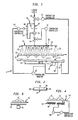
- Apparatus 1 includes a conveyor 10 which is an endless belt used in conveying articles 12 to be refrigerated. As such, articles 12 are the heat load that interact with the cryogen to be sprayed.
- a manifold 14 is provided having spray nozzles 16 to spray the cryogen as spray 18 against articles 12 within a spray zone 20.
- spray nozzle or nozzles as used herein and in the claims encompasses any device from which a spray could emanate.
- a spray nozzle used in the present invention could be a hole in a pipe.
- Spray zone 20 is defined by the spatial region taken up by sprays 18.
- conveyor 10 is an open structure (for instance a belt having openings such as holes or slots) to allow spray 18 to pass from nozzle 16 through spray zone 20 onto the articles and through conveyor 10.
- conveyor 10 is shown for exemplary purposes only and other conveyances such as hooks, rollers and etc. are possible.
- heat conductive element 22 is positioned below spray zone 20 and is provided with a surface 24 sized to contact the oversprayed liquid cryogenic refrigerant.
- heat conductive element 22 should be fabricated from aluminium, copper or other heat conductive material.
- heat conductive element 22 conducts heat from the surroundings. For instance, in many freezers that use liquid cryogen as a refrigerant, the interior of the freezer is approximately 50°C warmer than the liquid cryogen. Thus, the heat to be conducted by conductive element 22 originates in the environment that apparatus 1 operates.
- heat conductive element 22 downwardly slopes to a warmer end of the process so that any liquid cryogen that does not immediately vaporise upon contact with conductive element 22 will tend to flow down the slope of surface 24 of heat conductive element 22 to eventually be vaporised.
- a known vibrator 26 can be provided to produce a standing vibration within surface 24 of conductive element 22.
- peripheral lip sections 28 can preferably be provided to confine liquid to surface 24.
- surface 24 of heat conductive element should be sized to catch the overspray.
- sizing in practice requires both the width and length of surface 24 of heat conductive element 22 to be sized larger than spray zone 20.
- cryogenic liquid refrigerant should be sprayed as a two phase flow in order to produce the most efficient heat transfer.
- a liquid-vapour ratio of about 60:40 is preferred.
- the cryogenic liquid refrigerant is routed through a flow network having first and second legs 30 and 32 to divide the flow of the liquid cryogenic refrigerant into a first subsidiary stream within first leg 30 and a second subsidiary stream within second leg 32.
- the liquid cryogenic refrigerant is vaporised within second leg 32 by provision of a vaporiser 34 which can be fabricated from a coil of tubing of sufficient dimension to cause the required vaporisation.
- vaporiser 34 In an application of the present invention to a refrigeration device, vaporiser 34 would be positioned within the confines of such a device to avoid heat gain through such vaporiser 34 and hence, reduced thermal efficiency.
- the now vaporised second subsidiary stream is combined with the first stream by a mixing device 36 which could be simply a piping Tee.
- piping Tee could be provided with an orifice or preferably a spray nozzle to produce a jet of liquid to draw the vaporised second subsidiary stream into a turbulent mixture with the liquid of the first subsidiary stream and thereby produce a two phase flow to be introduced into manifold 14.
- Another option is to use an atomising nozzle in which the second subsidiary stream acts as the atomising fluid to atomise the liquid.
- apparatus 1 could be designed for steady state operation, preferably flexibility is built into its operation by a control system.
- the spray zone temperature of spray zone 20 is measured by a temperature sensor 38.
- a spray zone temperature signal representing the sensed temperature is introduced as an input into a temperature controller 40 which is preferably a programmable PID type of controller.
- An orifice plate 42 sets the maximum liquid flow rate within first leg 30. Orifice plate 42 together with the position of a proportional valve 66 (to be discussed hereinafter) produces a mostly constant ratio of flow passing through first and second legs 30 and 32 and thus, a designed normal operating ratio of liquid to vapour within the cryogen sprayed into spray zone 20 depending on the degree to which proportion valve 66 is open.
- mixing Tee 36 can itself incorporate an orifice or spray nozzle, a separate orifice plate could be dispensed with in a proper embodiment.
- the designed normal operating ratio can be 60:40 as discussed above.
- the use of an orifice plate acts to set the maxim flow which is a necessary design criteria for heat conductive element 22.
- the piping and valves contained within first and second legs 30 and 32 will contribute to the actual flow split.
- Temperature controller 40 has provision for setting a preset, desired temperature within spray zone 20. Temperature controller 40 in turn controls a proportional valve 44 to meter the flow of cryogen being introduced into spray zone 20. As temperature increases within spray zone 20, as measured by temperature sensor 38, temperature controller 40 commands proportional valve 44 to open to increase the flow rate of cryogen entering spray zone 20 and vice-versa. In such manner the temperature of spray zone 20 is maintained at a substantially constant preselected spray zone temperature.
- a heat conductive element temperature is sensed as an average temperature of heat conductive element 22. This is accomplished by separate temperature measurements effected by three temperature sensors 54, 56 and 58 positioned at the ends and centre of heat conductive element 22. With less effect, a single, centrally located temperature sensor can be used. These temperatures are averaged in a multi-channel temperature monitor 60 which produces an output signal referable to such average temperature and thus, the heat conductive element temperature. The output signal is fed as an input to a temperature controller 64, another programmable PID controller.
- Temperature controller 64 preferably has provision for registering a preset, reference percentage opening that is used to control the amount a proportional valve 66 is open.
- proportional valve 66 can represent an adjustable flow coefficient to control the desired liquid-vapour ratio (e.g. 60:40) of the cryogenic refrigerant to be sprayed.
- Temperature controller 64 also has provision for registering a preset reference temperature which is preferably about 10°C. above the temperature to be maintained within spray zone 20. Temperature controller 64 is preferably programmed in the following manner: In the event that the temperature as developed by temperature monitor 60 is warmer than the preset reference temperature, proportional valve 66 will remain at its preset, reference percentage of opening.
- proportional valve 66 will be commanded by temperature controller 64 to open and thereby increase the amount of vapour within the cryogenic refrigerant to be sprayed.
- proportional valve 66 returns to its preset percentage of opening as registered within temperature controller 64.
- a control valve 68 closes.
- the temperature at the lowest point of conductive element 22 is sensed by a temperature sensor 70 that produces an output signal referable to such sensed temperature which is fed as an input to temperature controller 72, preferably an on/off or thermostat controller.
- Temperature controller 72 is preset with a temperature that is selected to be above the boiling point temperature of the cryogen by a margin of typically about 80°C When the sensed temperature is above the present temperature, controller 72 functions as an interlock to activate closure of valve 68.
- the conductive heat transfer coefficient of heat conductive element 24 can be modified by imparting motion thereto. For instance, an oscillatory motion could be imparted to heat conductive element 24.
- FIG. 3 an embodiment of the present invention is illustrated in which a disc-like heat conductive element 74 having an upturned brim is provided. Heat conductive element 74 is rotated by a motor 76. In such illustration although no control system is illustrated, the same could be provided.
- a temperature sensor 84 is provided in such embodiment to sense the temperature of conductive element 82 and to supply such signal as an input to a controller 86, a programmable PID controller. Controller 86 regulates a power supply 88 to in turn regulate the power input to heating elements 80, thereby to control surface temperature of conductive element 82 to be above the boiling point temperature of the liquid cryogen.
- Controller 86 regulates a power supply 88 to in turn regulate the power input to heating elements 80, thereby to control surface temperature of conductive element 82 to be above the boiling point temperature of the liquid cryogen.
- This foregoing embodiment could also be used with apparatus 1 by its simple addition thereto. In such case heat conductive element 82 having embedded heating coils would be used in place of heat conductive element 22. On this point, the output of temperature sensor 70 would be used to control both the heating elements 80 and valve 68. Thus, at a preset temperature not only would valve 68 close but power would be applied to heating elements 80.
- controllers 40, 64, and 86 are readily available PID (Proportional, Integral, Differential) controllers with no specific manufacturer being preferred.
- PID Proportional, Integral, Differential
- the proportional, integral, and differential constants for each controller is in practice determined experimentally, in a manner known in the art.
- analogue controllers are also possible, but less preferred.
- heat conductive elements 24, 74 and 82 are illustrated as providing flat surfaces to contact the overspray, irregular surfaces could be provided to increase heat transfer. However, such irregular surfaces such as provided by a mesh or by ridges and etc. might tend to trap particles of the articles to be frozen. This could present a danger in case of a food freezing application of apparatus 1.
- the present invention encompasses embodiments with simply heat conductive elements alone without control systems, sprays of pure liquid rather than two phase flows, or partial controls such as control valve 68 to cut off the flow of liquid when surface temperature of the heat conductive element approaches the boiling point temperature of the cryogen.
- Any heat conductive element designed in accordance with the present invention must be massive enough to retain enough sensible heat energy to fully vaporise any transient overspray of liquid when the temperature a sensed by temperature sensor 70 falls below the preset temperature of controller 72.
- the maximum flow rate of the liquid content of the cryogen is set by an orifice plate 42 or the orifice or spray nozzle within mixing Tee 36. and such maximum flow rate that is used as a value for M l .
Landscapes
- Engineering & Computer Science (AREA)
- Life Sciences & Earth Sciences (AREA)
- Chemical & Material Sciences (AREA)
- Polymers & Plastics (AREA)
- Zoology (AREA)
- Food Science & Technology (AREA)
- Wood Science & Technology (AREA)
- Combustion & Propulsion (AREA)
- Physics & Mathematics (AREA)
- Mechanical Engineering (AREA)
- Thermal Sciences (AREA)
- General Engineering & Computer Science (AREA)
- Filling Or Discharging Of Gas Storage Vessels (AREA)
- Coating By Spraying Or Casting (AREA)
Applications Claiming Priority (2)
| Application Number | Priority Date | Filing Date | Title |
|---|---|---|---|
| US884423 | 1997-06-27 | ||
| US08/884,423 US5813237A (en) | 1997-06-27 | 1997-06-27 | Cryogenic apparatus and method for spraying a cryogen incorporating generation of two phase flow |
Publications (3)
| Publication Number | Publication Date |
|---|---|
| EP0887604A2 true EP0887604A2 (de) | 1998-12-30 |
| EP0887604A3 EP0887604A3 (de) | 1999-12-22 |
| EP0887604B1 EP0887604B1 (de) | 2005-07-20 |
Family
ID=25384598
Family Applications (1)
| Application Number | Title | Priority Date | Filing Date |
|---|---|---|---|
| EP98303373A Expired - Lifetime EP0887604B1 (de) | 1997-06-27 | 1998-04-30 | Versprühen einer Kryoflüssigkeit |
Country Status (7)
| Country | Link |
|---|---|
| US (1) | US5813237A (de) |
| EP (1) | EP0887604B1 (de) |
| JP (1) | JP4074376B2 (de) |
| CA (1) | CA2236702A1 (de) |
| DE (1) | DE69830873T2 (de) |
| NZ (1) | NZ330398A (de) |
| ZA (1) | ZA984434B (de) |
Cited By (1)
| Publication number | Priority date | Publication date | Assignee | Title |
|---|---|---|---|---|
| WO2004092668A1 (fr) * | 2003-04-07 | 2004-10-28 | L'air Liquide Societe Anonyme A Directoire Et Conseil De Surveillance Pour L'etude Et L'exploitation Des Procedes Georges Claude | Procede et installation de traitement -croutage/refroidissement/surgelation- de produits. |
Families Citing this family (20)
| Publication number | Priority date | Publication date | Assignee | Title |
|---|---|---|---|---|
| US6205799B1 (en) * | 1999-09-13 | 2001-03-27 | Hewlett-Packard Company | Spray cooling system |
| FR2853404A1 (fr) * | 2003-04-07 | 2004-10-08 | Air Liquide | Procede de determination de parametres de fonctionnement d'une installation comprenant une enceinte de refroidissement |
| DE102004020180A1 (de) * | 2004-04-22 | 2005-11-17 | Linde Ag | Verfahren und Vorrichtung zum Kühlen und/oder Gefrieren von Gegenständen |
| US7197883B2 (en) * | 2005-05-06 | 2007-04-03 | Praxair Technology, Inc. | Cooling or heating with multi-pass fluid flow |
| FR2887019B1 (fr) * | 2005-06-09 | 2007-07-20 | Air Liquide | Procede de refroidissement cryogenique de poudres mettant en oeuvre une strategie de controle anticipe |
| DE102006045324A1 (de) * | 2006-09-22 | 2008-04-03 | Linde Ag | Vorrichtung zum schnellen Frosten von Stoffen |
| DE102008008827A1 (de) * | 2008-02-12 | 2009-08-27 | Hupfer Metallwerke Gmbh & Co. Kg | Vorrichtung zur Verteilung gekühlter Speisen, insbesondere für Großküchen |
| WO2011149701A2 (en) * | 2010-05-27 | 2011-12-01 | Air Products And Chemicals, Inc. | Apparatus and method for providing a temperature-controlled gas |
| US20130125562A1 (en) * | 2011-11-22 | 2013-05-23 | Stephen A. McCormick | Ultrasonic impingement plate atomizer apparatus |
| US9638452B2 (en) * | 2012-09-12 | 2017-05-02 | Celltronix | Method and scalable devices for hyper-fast cooling and warming |
| DE102013019500A1 (de) * | 2013-11-21 | 2015-05-21 | Messer Slovenija D.O.O. | Vorrichtung und Verfahren zur Herstellung von Speiseeis |
| DK2955466T3 (da) * | 2014-06-13 | 2020-03-16 | John Bean Technologies Ab | Temperaturbehandlingsanordning og fremgangsmåde til at størkne væskeportioner |
| US20160030607A1 (en) * | 2014-08-04 | 2016-02-04 | Michael D. Newman | Heat flux control for liquid nitrogen sprays |
| US20170038105A1 (en) * | 2015-08-03 | 2017-02-09 | Michael D. Newman | Pulsed liquid cryogen flow generator |
| US20170038117A1 (en) * | 2015-08-03 | 2017-02-09 | Michael D. Newman | Pulsed liquid-gas entrained cryogen flow generator |
| KR20190126157A (ko) * | 2017-03-17 | 2019-11-08 | 티이엘 에프에스아이, 인코포레이티드 | 극저온 유체 스프레이들과 같은 유체 스프레이들을 이용한 마이크로 전자 기판들의 처리를 모니터링하기 위한 시스템 및 방법 |
| US20190170424A1 (en) * | 2017-12-01 | 2019-06-06 | Shanghai Ocean University | Jet nozzle structure of impact-type freezer |
| CN109269182B (zh) * | 2018-08-31 | 2021-01-08 | 枣庄市永兴板栗加工有限公司 | 一种适于改善食品松软或酥脆均匀性的冷却设备 |
| CN108889568B (zh) * | 2018-09-03 | 2024-04-12 | 东山欧凯金属塑料制品有限公司 | 物料上色机 |
| CN113560061B (zh) * | 2020-04-29 | 2023-02-03 | 南京航太机电有限公司 | 一种可调温式低温气体喷枪系统 |
Citations (2)
| Publication number | Priority date | Publication date | Assignee | Title |
|---|---|---|---|---|
| US2479821A (en) | 1946-03-30 | 1949-08-23 | Shell Dev | Process and apparatus for refrigeration |
| US4726195A (en) | 1986-08-22 | 1988-02-23 | Air Products And Chemicals, Inc. | Cryogenic forced convection refrigerating system |
Family Cites Families (23)
| Publication number | Priority date | Publication date | Assignee | Title |
|---|---|---|---|---|
| US3277657A (en) * | 1965-09-15 | 1966-10-11 | Integral Process Syst Inc | Method and apparatus for flash freezing various products |
| FR1471319A (fr) * | 1966-03-05 | 1967-03-03 | Ts Lab Chlodnictwa | Procédé pour refroidir ou congeler des produits en chambre froide au moyen d'azoteliquide |
| US3403527A (en) * | 1967-06-01 | 1968-10-01 | Air Prod & Chem | Transverse-parallel flow cryogenic freezer |
| US3421336A (en) * | 1967-06-05 | 1969-01-14 | Union Carbide Corp | Intransit liquefied gas refrigeration system |
| US3611738A (en) * | 1970-04-15 | 1971-10-12 | Union Carbide Corp | Frozen product refrigeration and dehumidification system |
| US3788825A (en) * | 1970-10-06 | 1974-01-29 | Black Sivalls & Bryson Inc | Method of vaporizing and combining a liquefied cryogenic fluid stream with a gas stream |
| US3871186A (en) * | 1973-08-23 | 1975-03-18 | Integral Process Syst Inc | Apparatus and method for refrigerating articles |
| US4171625A (en) * | 1977-11-02 | 1979-10-23 | Formax, Inc. | Cryogenic freezing tunnel |
| US4350027A (en) * | 1981-10-05 | 1982-09-21 | Lewis Tyree Jr | Cryogenic refrigeration apparatus |
| US4481780A (en) * | 1984-01-06 | 1984-11-13 | Union Carbide Corporation | Process for the generation of a cold gas |
| US4783972A (en) * | 1987-10-29 | 1988-11-15 | Liquid Carbonic Corporation | N2 tunnel freezer |
| US4813245A (en) * | 1988-01-13 | 1989-03-21 | Liquid Air Corporation | High efficiency linear freezer |
| FR2641854B1 (fr) * | 1988-12-28 | 1994-01-14 | Carboxyque Francaise | Procede et dispositif de regulation d'un debit de co2 liquide, et application a un tunnel de refroidissement |
| US4934151A (en) * | 1989-07-07 | 1990-06-19 | Kyokujitsu Company., Ltd. | Continuous multistage thermal processing apparatus, freezing control method for use by the apparatus, and apparatus for preparing a recording medium for the control method |
| US5054292A (en) * | 1990-07-13 | 1991-10-08 | Air Products And Chemicals, Inc. | Cryogenic freezer control |
| US5186008A (en) * | 1991-11-25 | 1993-02-16 | The Boc Group, Inc. | Cryogenic freezer apparatus and method |
| FR2686403B1 (fr) * | 1992-01-21 | 2001-02-09 | Air Liquide | Procede et dispositif de congelation. |
| GB9303212D0 (en) * | 1993-02-17 | 1993-03-31 | Air Prod & Chem | Method and apparatus for freezing |
| US5417074A (en) * | 1993-07-26 | 1995-05-23 | Air Products And Chemicals, Inc. | Liquid nitrogen immersion/impingement freezing method and apparatus |
| US5394704A (en) * | 1993-11-04 | 1995-03-07 | The United States Of America As Represented By The Administrator Of The National Aeronautics And Space Administration | Alternate method for achieving temperature control in the -160 to +90 degrees Celcius range |
| US5460015A (en) * | 1994-04-28 | 1995-10-24 | Liquid Carbonic Corporation | Freezer with imperforate conveyor belt |
| US5467612A (en) * | 1994-04-29 | 1995-11-21 | Liquid Carbonic Corporation | Freezing system for fragible food products |
| US5740678A (en) * | 1995-05-24 | 1998-04-21 | The Boc Group, Inc. | Impingement jet freezer and method |
-
1997
- 1997-06-27 US US08/884,423 patent/US5813237A/en not_active Expired - Fee Related
-
1998
- 1998-04-30 DE DE69830873T patent/DE69830873T2/de not_active Expired - Fee Related
- 1998-04-30 EP EP98303373A patent/EP0887604B1/de not_active Expired - Lifetime
- 1998-05-05 CA CA002236702A patent/CA2236702A1/en not_active Abandoned
- 1998-05-11 NZ NZ330398A patent/NZ330398A/xx unknown
- 1998-05-25 ZA ZA984434A patent/ZA984434B/xx unknown
- 1998-06-29 JP JP18244598A patent/JP4074376B2/ja not_active Expired - Fee Related
Patent Citations (2)
| Publication number | Priority date | Publication date | Assignee | Title |
|---|---|---|---|---|
| US2479821A (en) | 1946-03-30 | 1949-08-23 | Shell Dev | Process and apparatus for refrigeration |
| US4726195A (en) | 1986-08-22 | 1988-02-23 | Air Products And Chemicals, Inc. | Cryogenic forced convection refrigerating system |
Cited By (2)
| Publication number | Priority date | Publication date | Assignee | Title |
|---|---|---|---|---|
| WO2004092668A1 (fr) * | 2003-04-07 | 2004-10-28 | L'air Liquide Societe Anonyme A Directoire Et Conseil De Surveillance Pour L'etude Et L'exploitation Des Procedes Georges Claude | Procede et installation de traitement -croutage/refroidissement/surgelation- de produits. |
| US7805951B2 (en) | 2003-04-07 | 2010-10-05 | L'air Liquide Societe Anonyme A Directoire Et Conseil De Surveillance Pour L'etude Et L'exploitation Des Procedes Georges Claude | Method and apparatus for the crust-freezing/cooling/deep-freezing treatment of products |
Also Published As
| Publication number | Publication date |
|---|---|
| JP4074376B2 (ja) | 2008-04-09 |
| ZA984434B (en) | 1998-12-02 |
| CA2236702A1 (en) | 1998-12-27 |
| NZ330398A (en) | 2000-01-28 |
| EP0887604B1 (de) | 2005-07-20 |
| JPH1194421A (ja) | 1999-04-09 |
| US5813237A (en) | 1998-09-29 |
| EP0887604A3 (de) | 1999-12-22 |
| DE69830873D1 (de) | 2005-08-25 |
| DE69830873T2 (de) | 2006-04-20 |
Similar Documents
| Publication | Publication Date | Title |
|---|---|---|
| EP0887604B1 (de) | Versprühen einer Kryoflüssigkeit | |
| CA1085178A (en) | Apparatus for refrigeration treatment | |
| EP0891945B1 (de) | Vorrichtung zur Herstellung von feinen Schneeteilchen mittels eines flüssigen Kohlendioxidstroms | |
| US5090209A (en) | Enthalpy control for co2 refrigeration system | |
| CA1056612A (en) | Method and apparatus for cooling material using liquid co2 | |
| US4866946A (en) | Spiral cryogenic freezer | |
| US5524848A (en) | Humidification process and apparatus | |
| US4726195A (en) | Cryogenic forced convection refrigerating system | |
| US6038868A (en) | Freezer apparatus | |
| EP0667503B1 (de) | Gefriertunnel | |
| JPS61105070A (ja) | 冷却あるいは冷凍の方法及び装置 | |
| JP2003083595A (ja) | 低温温度制御装置及び方法 | |
| US5477691A (en) | Liquid cryogen delivery system | |
| US6284302B1 (en) | Method and device for cooling and atomizing liquid or paste-like substances | |
| CA1297306C (en) | Method and apparatus for gas flow control in a cryogenic freezer | |
| KR20030029523A (ko) | 자유유동 냉동품의 액상 공급 제조용 극저온 처리기 | |
| EP1039954A1 (de) | Feuerlöschvorrichtung | |
| KR101185693B1 (ko) | 한제의 온도를 제어하는 장치 및 방법 | |
| US6519956B2 (en) | Device and method for operating a refrigeration cycle without evaporator icing | |
| CA2772948A1 (en) | Apparatus and method for providing a temperature-controlled gas | |
| PL176753B1 (pl) | Ciekły gaz do ochładzania i zamrażania łatwo psujących się artykułów spożywczych oraz urządzenie do przechowywania i rozprowadzania ciekłego gazu w pojemnikach do łatwo psujących się artykułów spożywczych | |
| US4969335A (en) | Refrigeration apparatus for transport containers | |
| EP1444469B1 (de) | Schneeherstellung | |
| US20060230767A1 (en) | Special effects cloud generation system | |
| US3824806A (en) | Apparatus for refrigerating articles |
Legal Events
| Date | Code | Title | Description |
|---|---|---|---|
| PUAI | Public reference made under article 153(3) epc to a published international application that has entered the european phase |
Free format text: ORIGINAL CODE: 0009012 |
|
| AK | Designated contracting states |
Kind code of ref document: A2 Designated state(s): BE DE FR GB IT NL SE |
|
| AX | Request for extension of the european patent |
Free format text: AL;LT;LV;MK;RO;SI |
|
| PUAL | Search report despatched |
Free format text: ORIGINAL CODE: 0009013 |
|
| AK | Designated contracting states |
Kind code of ref document: A3 Designated state(s): AT BE CH CY DE DK ES FI FR GB GR IE IT LI LU MC NL PT SE |
|
| AX | Request for extension of the european patent |
Free format text: AL;LT;LV;MK;RO;SI |
|
| 17P | Request for examination filed |
Effective date: 20000614 |
|
| AKX | Designation fees paid |
Free format text: BE DE FR GB IT NL SE |
|
| 17Q | First examination report despatched |
Effective date: 20021014 |
|
| GRAP | Despatch of communication of intention to grant a patent |
Free format text: ORIGINAL CODE: EPIDOSNIGR1 |
|
| GRAS | Grant fee paid |
Free format text: ORIGINAL CODE: EPIDOSNIGR3 |
|
| GRAA | (expected) grant |
Free format text: ORIGINAL CODE: 0009210 |
|
| AK | Designated contracting states |
Kind code of ref document: B1 Designated state(s): BE DE FR GB IT NL SE |
|
| REG | Reference to a national code |
Ref country code: GB Ref legal event code: FG4D |
|
| REF | Corresponds to: |
Ref document number: 69830873 Country of ref document: DE Date of ref document: 20050825 Kind code of ref document: P |
|
| REG | Reference to a national code |
Ref country code: SE Ref legal event code: TRGR |
|
| ET | Fr: translation filed | ||
| PLBE | No opposition filed within time limit |
Free format text: ORIGINAL CODE: 0009261 |
|
| STAA | Information on the status of an ep patent application or granted ep patent |
Free format text: STATUS: NO OPPOSITION FILED WITHIN TIME LIMIT |
|
| 26N | No opposition filed |
Effective date: 20060421 |
|
| PGFP | Annual fee paid to national office [announced via postgrant information from national office to epo] |
Ref country code: DE Payment date: 20080602 Year of fee payment: 11 |
|
| PGFP | Annual fee paid to national office [announced via postgrant information from national office to epo] |
Ref country code: BE Payment date: 20080527 Year of fee payment: 11 Ref country code: IT Payment date: 20080428 Year of fee payment: 11 |
|
| PGFP | Annual fee paid to national office [announced via postgrant information from national office to epo] |
Ref country code: SE Payment date: 20080429 Year of fee payment: 11 Ref country code: NL Payment date: 20080424 Year of fee payment: 11 |
|
| PGFP | Annual fee paid to national office [announced via postgrant information from national office to epo] |
Ref country code: FR Payment date: 20080417 Year of fee payment: 11 |
|
| PGFP | Annual fee paid to national office [announced via postgrant information from national office to epo] |
Ref country code: GB Payment date: 20080429 Year of fee payment: 11 |
|
| BERE | Be: lapsed |
Owner name: THE *BOC GROUP INC. Effective date: 20090430 |
|
| GBPC | Gb: european patent ceased through non-payment of renewal fee |
Effective date: 20090430 |
|
| NLV4 | Nl: lapsed or anulled due to non-payment of the annual fee |
Effective date: 20091101 |
|
| REG | Reference to a national code |
Ref country code: FR Ref legal event code: ST Effective date: 20091231 |
|
| PG25 | Lapsed in a contracting state [announced via postgrant information from national office to epo] |
Ref country code: DE Free format text: LAPSE BECAUSE OF NON-PAYMENT OF DUE FEES Effective date: 20091103 |
|
| PG25 | Lapsed in a contracting state [announced via postgrant information from national office to epo] |
Ref country code: NL Free format text: LAPSE BECAUSE OF NON-PAYMENT OF DUE FEES Effective date: 20091101 |
|
| PG25 | Lapsed in a contracting state [announced via postgrant information from national office to epo] |
Ref country code: GB Free format text: LAPSE BECAUSE OF NON-PAYMENT OF DUE FEES Effective date: 20090430 Ref country code: FR Free format text: LAPSE BECAUSE OF NON-PAYMENT OF DUE FEES Effective date: 20091222 |
|
| PG25 | Lapsed in a contracting state [announced via postgrant information from national office to epo] |
Ref country code: BE Free format text: LAPSE BECAUSE OF NON-PAYMENT OF DUE FEES Effective date: 20090430 |
|
| PG25 | Lapsed in a contracting state [announced via postgrant information from national office to epo] |
Ref country code: IT Free format text: LAPSE BECAUSE OF NON-PAYMENT OF DUE FEES Effective date: 20090430 |
|
| PG25 | Lapsed in a contracting state [announced via postgrant information from national office to epo] |
Ref country code: SE Free format text: LAPSE BECAUSE OF NON-PAYMENT OF DUE FEES Effective date: 20090501 |