EP0887517B1 - Structure of overhead-valve internal combustion engine - Google Patents
Structure of overhead-valve internal combustion engine Download PDFInfo
- Publication number
- EP0887517B1 EP0887517B1 EP98111621A EP98111621A EP0887517B1 EP 0887517 B1 EP0887517 B1 EP 0887517B1 EP 98111621 A EP98111621 A EP 98111621A EP 98111621 A EP98111621 A EP 98111621A EP 0887517 B1 EP0887517 B1 EP 0887517B1
- Authority
- EP
- European Patent Office
- Prior art keywords
- valve
- rocker arm
- cylinder head
- aforesaid
- engine
- Prior art date
- Legal status (The legal status is an assumption and is not a legal conclusion. Google has not performed a legal analysis and makes no representation as to the accuracy of the status listed.)
- Expired - Lifetime
Links
- 238000002485 combustion reaction Methods 0.000 title claims description 24
- 230000007246 mechanism Effects 0.000 claims description 71
- 230000002093 peripheral effect Effects 0.000 claims description 19
- 238000005520 cutting process Methods 0.000 claims description 4
- 239000003921 oil Substances 0.000 description 27
- 238000005461 lubrication Methods 0.000 description 8
- 238000000034 method Methods 0.000 description 8
- 230000006698 induction Effects 0.000 description 7
- 238000013461 design Methods 0.000 description 6
- 230000008569 process Effects 0.000 description 6
- 239000010687 lubricating oil Substances 0.000 description 5
- 238000003754 machining Methods 0.000 description 3
- 239000000463 material Substances 0.000 description 3
- 238000012545 processing Methods 0.000 description 3
- 230000009471 action Effects 0.000 description 2
- 230000008859 change Effects 0.000 description 2
- 230000004048 modification Effects 0.000 description 2
- 238000012986 modification Methods 0.000 description 2
- XAGFODPZIPBFFR-UHFFFAOYSA-N aluminium Chemical compound [Al] XAGFODPZIPBFFR-UHFFFAOYSA-N 0.000 description 1
- 229910052782 aluminium Inorganic materials 0.000 description 1
- 238000013459 approach Methods 0.000 description 1
- 230000000694 effects Effects 0.000 description 1
- 230000005484 gravity Effects 0.000 description 1
- 230000001050 lubricating effect Effects 0.000 description 1
- 238000004519 manufacturing process Methods 0.000 description 1
Images






Classifications
-
- F—MECHANICAL ENGINEERING; LIGHTING; HEATING; WEAPONS; BLASTING
- F02—COMBUSTION ENGINES; HOT-GAS OR COMBUSTION-PRODUCT ENGINE PLANTS
- F02F—CYLINDERS, PISTONS OR CASINGS, FOR COMBUSTION ENGINES; ARRANGEMENTS OF SEALINGS IN COMBUSTION ENGINES
- F02F1/00—Cylinders; Cylinder heads
- F02F1/24—Cylinder heads
- F02F1/26—Cylinder heads having cooling means
- F02F1/28—Cylinder heads having cooling means for air cooling
- F02F1/30—Finned cylinder heads
-
- F—MECHANICAL ENGINEERING; LIGHTING; HEATING; WEAPONS; BLASTING
- F01—MACHINES OR ENGINES IN GENERAL; ENGINE PLANTS IN GENERAL; STEAM ENGINES
- F01L—CYCLICALLY OPERATING VALVES FOR MACHINES OR ENGINES
- F01L1/00—Valve-gear or valve arrangements, e.g. lift-valve gear
- F01L1/12—Transmitting gear between valve drive and valve
-
- F—MECHANICAL ENGINEERING; LIGHTING; HEATING; WEAPONS; BLASTING
- F01—MACHINES OR ENGINES IN GENERAL; ENGINE PLANTS IN GENERAL; STEAM ENGINES
- F01L—CYCLICALLY OPERATING VALVES FOR MACHINES OR ENGINES
- F01L1/00—Valve-gear or valve arrangements, e.g. lift-valve gear
- F01L1/12—Transmitting gear between valve drive and valve
- F01L1/18—Rocking arms or levers
- F01L1/181—Centre pivot rocking arms
- F01L1/182—Centre pivot rocking arms the rocking arm being pivoted about an individual fulcrum, i.e. not about a common shaft
-
- F—MECHANICAL ENGINEERING; LIGHTING; HEATING; WEAPONS; BLASTING
- F02—COMBUSTION ENGINES; HOT-GAS OR COMBUSTION-PRODUCT ENGINE PLANTS
- F02B—INTERNAL-COMBUSTION PISTON ENGINES; COMBUSTION ENGINES IN GENERAL
- F02B2275/00—Other engines, components or details, not provided for in other groups of this subclass
- F02B2275/34—Lateral camshaft position
-
- F—MECHANICAL ENGINEERING; LIGHTING; HEATING; WEAPONS; BLASTING
- F02—COMBUSTION ENGINES; HOT-GAS OR COMBUSTION-PRODUCT ENGINE PLANTS
- F02F—CYLINDERS, PISTONS OR CASINGS, FOR COMBUSTION ENGINES; ARRANGEMENTS OF SEALINGS IN COMBUSTION ENGINES
- F02F1/00—Cylinders; Cylinder heads
- F02F1/24—Cylinder heads
- F02F2001/244—Arrangement of valve stems in cylinder heads
- F02F2001/245—Arrangement of valve stems in cylinder heads the valve stems being orientated at an angle with the cylinder axis
Definitions
- This invention concerns a structure of an overhead-valve internal combustion engine. More specifically, it concerns the configuration of the valve operating mechanism which operates the valves in an overhead-valve type internal combustion engine with an intake valve and an exhaust valve, and the lubrication device in the valve operating mechanism of the same kind of engine.
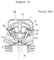
- Figures 18 and 19 show an example of an air-cooled single-cylinder overhead-valve four-cycle internal combustion engine with the aforesaid pent roof combustion chamber which belongs to the prior art.
- Figure 18 is a cross section of the engine which includes the cylinder and the push rods.
- Figure 19 is a cross section taken along line Z-Z in Figure 18.
- valve spring 18 In an OHV engine like this, to insure that the action of cam 17a is transmitted reliably to induction/exhaust valve 14 through push rods 15, the aforesaid valve spring 18 must have a relatively large spring constant, meaning that a strong spring must be used; and rocker arms 13 must have a relatively large diameter.
- an adjustment screw (not pictured) is provided to adjust the clearance between the contacting portions of rocker arms 11 and push rods 15.
- the aforesaid head cover 9 is hermetically sealed to top surface 8b, the upper surface of peripheral wall 8c, which surrounds the head.
- the aforesaid rocker arm supporting base 22 for the rocker arms is bolted to an area in the center of upper surface 8a which is lower than the said top surface 8b by a fixed amount.
- top surface 8b, on which cover 9 is mounted, and mounting surface 8a, on which rocker arm supporting base 22 is mounted are at different heights. This means that they must be machined in a two-stage process or that the machinist must change tools in mid-process. This increases the number of processes required and incurs an extra cost for set-up.
- Breather passage 131 which connects crankcase 101 and valve operating mechanism chamber 102, is formed within the walls of cylinder barrel 116 and cylinder head 118.
- the end portion 131a of the said breather passage 131 in valve operating mechanism chamber 102 faces from above intake valve 151 toward the point where valve stem 152a of exhaust valve 152 and rocker arm 162 come in contact.
- Branching passage 131b faces to the point where valve stem 151a of intake valve 151 and rocker arm 161 come in contact.
- valve operating mechanism chamber 102 When the air forced into the aforesaid valve operating mechanism chamber 102 goes through breather valve 108, the lubricating oil is separated out. The air enters breather chamber 109, travels through breather tube 132 and is returned to carburetor 111. The oil flows down the interior surface of valve operating mechanism chamber 102. It goes through the space around push rod 122 and tappet 121 and is recovered in crankcase 101.
- EP-A-279445 Another engine with parallel intake and exhaust valves is disclosed in EP-A-279445. This engine is horizontally oriented such that the intake valve is located below the exhaust valve. The engine has a breather passage leading from the crankcase to the valve operating chamber at a point directly above the stem of the exhaust valve. Oil is supplied through the breather passage to the region where the exhaust valve is engaged by a rocker arm, and flows then by gravity also to the intake valve.
- GB-A-684221 An example for an engine with a pent roof combustion chamber and non-parallel valves is disclosed in GB-A-684221.
- the valve operating mechanism of this engine is lubricated by oil supplied from a passage in the cylinder head to the interior of a hollow overhead camshaft. From there, the oil flows through individual channels to bearings of rocker arms for driving the valves.
- a lubrication device for overhead-valve engine having a first breather passage connecting a valve operation mechanism chamber over a cylinder head provided with an intake valve and an exhaust valve, and a crankcase, and passing through said cylinder head and a cylinder, comprises an opening of a first breather passage, a groove, and a second breather passage.
- the opening of the first breather passage is provided in a vicinity of a spring retainer for the intake valve, which faces the valve operating mechanism chamber.
- the groove is formed by cutting on the cylinder head facing the valve operating chamber and connecting an end of the groove to the opening.
- the second breather passage is formed by a tunnel-like passage provided by a guide wall standing in the valve operating mechanism chamber and a peripheral wall of said cylinder head and connecting another end of said groove to the exhaust valve.
- the second breather passage mentioned above is further comprising a protruding portion of a gasket provided between a top surface of the cylinder head and a head cover, which covers the tunnel-like passage.
- the second breather passage connects spaces surrounded with ring-shaped ribs which protrude from spring retainers for an intake valve spring and an exhaust valve spring by the groove formed by cutting on a portion of the ring-shaped rib and the tunnel-like passage.
- the lubricating oil splashed around in the crankcase goes through the first breather passage and flows out through the opening of the valve operating mechanism chamber in the vicinity of the spring retainer for intake valve. From the vicinity of the said intake valve, the oil goes through the second breather passage, which comprises a groove formed on the valve operating mechanism chamber surface of the cylinder head and a tunnel surrounded by a guide wall and the peripheral wall of the cylinder head. This passage conducts the oil to the vicinity of the exhaust valve.
- a sufficient quantity of lubricating oil can be supplied not only to the area around the intake valve, but also, via the second breather passage, to the area around the exhaust valve, where extreme temperatures are experienced.
- the entire valve operating mechanism can be lubricated uniformly.
- the aforesaid second breather passage can be created using the valve operating mechanism chamber surface of the cylinder head and the protruding portion of the gasket, no special parts need to be purchased or made, and the parts count can be reduced.
- the lubricating oil splashed around in the crankcase goes through the opening in the vicinity of the spring retainer for intake valve. From the vicinity of the said intake valve, the suspended oil goes through the second breather passage formed by a groove and a tunnel which is surrounded by a straight guide wall and the peripheral wall of the cylinder head. This passage conducts the suspended oil to the vicinity of the exhaust valve. In this fashion, a sufficient quantity of lubricating oil can be supplied not only to the area around the intake valve, but also to the area around the exhaust valve, where extreme temperatures are experienced. The entire valve operating mechanism can be lubricated uniformly.
- the aforesaid breather passage can be created using the valve operating mechanism chamber surface of the cylinder head and the entrance portion of the oil guide washer plate, no special parts need to be used, and it is easy to assemble the valve operating mechanism chamber. In other words, the parts count can be reduced, the entire valve operating mechanism can be lubricated perfectly with a low cost.
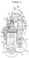
- Figure 1 is a cross section of an air-cooled overhead-valve single cylinder four-cycle internal combustion engine. This drawing shows primarily the cylinder and the push rod.
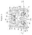
- Figure 2 is a plan view of the engine in Figure 1 with the head cover removed.
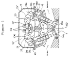
- Figure 3 is a cross section taken along line A-A in Figure 2.
- Figure 4 corresponds to Figure 2 and shows a second engine configuration.
- Figure 5 is a cross section taken along line B-B in Figure 4.
- Figure 6 is the view of the cylinder head in Figure 5 as seen from arrow C in that figure (when seen through the valve operating mechanism).
- Figure 7 corresponds to Figure 2 and shows a third engine configuration.
- Figure 8 is a cross section taken along line D-D in Figure 7.
- Figure 9 is a view of the same cylinder head as seen from arrow E in Figure 8 (when seen through the valve operating mechanism).
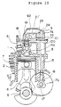
- Figure 10 corresponds to Figure 1 and shows an air-cooled overhead-valve four-cycle internal combustion engine which is an example of the preferred embodiment of this invention. This shows the cross section showing the center of the cylinder and the push rod.
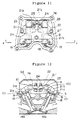
- Figure 11 is a plan view of the valve operating mechanism from the engine in Figure 1 with the head cover removed according to the preferred embodiment of this invention.
- Figure 12 is a cross section taken along line F-F in Figure 11.
- Figure 13 shows a plan view of the valve operating mechanism in a multipurpose OHV engine which is the preferred embodiment of this invention. The head cover has been removed.
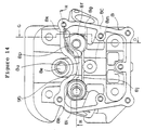
- Figure 14 is a plan view of the cylinder head in the aforesaid preferred embodiment.
- Figure 15 is a cross section taken along line G-G in Figure 14.
- Figure 16 is a cross section taken along line H-H in Figure 14.
- Figure 17 shows the oil guide washer plate in the aforesaid preferred embodiment.
- (a) is a frontal view and
- (b) is a plan view.
- Figure 18 is a lateral cross section, cut along the center line of the cylinder and push rod, of a multipurpose OHV engine which is an example of the prior art.
- Figure 19 is a cross section taken along line Z-Z in Figure 18.
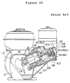
- Figure 20 is a vertical cross section of another example of the prior art.
- Figure 21 is a vertical cross section of the prior art shown in Figure 20.
- Figure 22 is a plan view of the valve operating mechanism of the prior art shown in Figure 20.
- Figure 1 is a cross section of an air-cooled overhead-valve single cylinder four-cycle internal combustion engine. This drawing shows primarily the cylinder and the push rod.
- Figure 2 is a plan view of the engine in Figure 1 with the head cover removed.
- Figure 3 is a cross section taken along line A-A in Figure 2.
- 9 is the head cover, which encloses the valve operating mechanism (to be discussed shortly). This cover is mounted on top surface 101 of peripheral wall 8c, which surrounds the aforesaid cylinder head 8.
- the aforesaid combustion chamber 1 is a pent roof-type chamber. This is why, as can be seen in Figure 3, the aforesaid intake valve 14a and exhaust valve 14b are arranged so that their respective axes 103 and 104 angle away from the center line 102 of the cylinder. That is to say, the valves incline with respect to the center line at angle in the fashion of radiating lines.
- 21 is the rocker arm for the intake valve.
- 21' is the rocker arm for the exhaust valve. It is placed on the opposite side of center line 102 so that it is symmetrical with respect to the said rocker arm 21.
- 23 are the rocker arm shafts, and 22 is the rocker arm supporting base.
- the aforesaid rocker arms 21 and 21', rocker arm shafts 23, rocker arm supporting base 22, cam 17a, tappet 16 and push rod 15 comprise the valve operating mechanism.
- 92 is the valve operating mechanism chamber to install the valve operating mechanism, and it is covered by the head cover 9.
- the aforesaid rocker arm supporting base 22 is fixed by four bolts 25 to mounting surfaces 100, the upper surfaces of the four bosses 8d which project from peripheral wall 8c of cylinder head 8 toward the center of the head.
- the rocker arm supporting base At the ends of the rocker arm supporting base are four retainers 22a and 22b, which support the two rocker arms 23 for the aforesaid intake and exhaust valves at both their ends. These retainers also immobilize the two rocker arm shafts 23 so that they are parallel to each other.
- the aforesaid rocker arm shafts 23 are mounted onto the aforesaid rocker arm supporting base 22 so that their axes 23a are at a right angle with respect to line 105, the line which links the centers of intake valve 14a and exhaust valve 14b.
- rocker arm 21 which controls the aforesaid intake valve
- rocker arm 21' which controls the exhaust valve
- Shafts 23 must have a diameter large enough to provide a sufficient bearing area.
- 21b and 21'b are the first arm units on the ends of the arms which come in contact with push rods 15 in the axial direction of the aforesaid arms 23.
- 21c and 21'c are the second arm units on the ends of the arms which come in contact with intake valve 14a and exhaust valve 14b.
- Adjustment screws 24 which serve to adjust the clearance of the valve operating mechanism, are screwed into the aforesaid arm units 21b and 21'b.
- On the end of each adjustment screw 24 is a spherical bearing.
- the push rods 15 for the aforesaid intake and exhaust valves are linked to the rocker arms through these bearings.
- the aforesaid rocker arm units 21c and 21'c contact with intake valve 14a and exhaust valve 14b through straps 21a, which are made from a material that is highly resistant to be worn away.
- Mounting surface 100 for rocker arm supporting base 22 on the upper surface of cylinder head 8 is coplanar (unifacial) with top surface 101, on which head cover 9 is mounted.
- the aforesaid mounting surface 100 and top surface 101 should be on the same plane. However, it would also be acceptable for them to be at slightly different levels. In this case, for the purpose of machining the surfaces, it would be better if the aforesaid top surface 101, which is on the outside of the head, could be slightly lower than the mounting surface 100, which is in the interior.
- induction/exhaust valves 14 open and close according to a timing determined by camshaft 17, whose rotating speed is reduced to half that of crankshaft 5 by a timing gear (not pictured). That is to say, when camshaft 17 rotates, push rods 15 are thrust upward, and rocker arm 21, which operates the intake valve, or rocker arm 21', which operates the exhaust valve, rotates around shaft 23. Intake valve 14a or exhaust valve 14b is pushed upward against the elastic force of its respective valve spring 18, and the valve opens.
- valve springs 18 In an OHV engine like this, to insure that the action of cam 17a is transmitted reliably to induction/exhaust valve 14 through push rods 15, the aforesaid valve springs 18 must have a relatively large spring constant, meaning that strong springs must be used; and, as was mentioned above, rocker arms 23 must have a relatively large diameter.
- Rocker arm shafts 23 for the intake and exhaust valves are supported in two places by retainers 22a and 22b of rocker arm supporting base 22. This minimizes the torsion force which acts on the shafts when the rocker arms operate and allows us to achieve rocker arms and a shaft support mechanism with a high degree of strength.
- FIG. 4 through 6 27 is the rocker arm supporting base; it is fixed to mounting surface 100 by means of two bolts 25 at bosses 8d, which project from peripheral wall 8c of cylinder head 8 toward the interior of the head at a right angle to line 105, the line which links the centers of the aforesaid intake valve 14a and exhaust valve 14b to the center line 102 of the cylinder.
- mounting surface 100 of the aforesaid rocker arm supporting base 27 is either coplanar with top surface 101 on which head cover 9 is mounted or slightly higher than that top surface.
- rocker arm shafts 28 are arranged so as to have an inclining angle with respect to the center line 102 of the cylinder, as can be seen in Figure 5.
- Their axes 28a can form right angles with respect to the center lines 14a 1 and 14b 1 of intake and exhaust valves 14a and 14b, which are arranged to the radiate direction with respect to the center line 102 of the cylinder head.
- 26 is the rocker arm for the intake valve; 26' is the rocker arm for the exhaust valve. They are arranged symmetrically with respect to the center line 102 of the cylinder. The tubular portions in their centers are inserted into the aforesaid rocker arm shafts 28 in such a way that the arms are free to swing and their movement in the axial direction can be controlled.
- rocker arm shafts 28 are surrounded by the aforesaid rocker arm 26 for the intake valve and 27' for the exhaust valve. Their ends 26b and 26'b come in contact with push rods 15. Their other ends, 26c and 26'c, come in contact with intake valve 14a and exhaust valve 14b.
- Adjustment screws 24 on ends 26b and 26'b are used to adjust the clearance of the valve operating mechanism.
- the rocker arms are engaged with push rods 15 through the spherical bearings on the ends of the adjustment screws.
- mounting surface 100 for the rocker arm supporting base on the top of cylinder head 8 is either coplanar with top surface 101 on top of peripheral wall 8c, to which head cover 9 is mounted, or slightly higher than that top surface.
- This design means that the two surfaces can be processed in a single stage, and the number of required processes is reduced.
- rocker arm supporting base 27 is smaller and the area of the said mounting surface 100 can be smaller than in the aforesaid first preferred embodiment. This further simplifies the processing of the said mounting surface 100 and reduces the number of processes.
- the length of rocker arms 26 and 26' can be increased, which provides some leeway in the design of the valve operating mechanism and prevents excessive force from being exerted in that mechanism.
- Figures 7 through 9 show a third engine configuration.
- Figure 7 is a plan view which corresponds to Figure 2.
- Figure 8 is a cross section taken along line D-D in Figure 7.
- Figure 9 is a view of the same cylinder head as seen from arrow E in Figure 8.
- This configuration is a modification of the previous second one; the arrangement of the rocker arm supporting base and shafts differs from that in the second preferred embodiment.
- 32 is the rocker arm supporting base; it is fixed to mounting surface 100 by means of two bolts 25 on bosses 8d, which project from peripheral wall 8c of cylinder head 8 toward the interior of the head at a right angle to line 105, the line which links the centers of the aforesaid intake valve 14a and exhaust valve 14b to the center line 102 of the cylinder.
- mounting surface 100 of the aforesaid rocker arm supporting base 32 is either coplanar with top surface 101 on which head cover 9 is mounted or slightly higher than that top surface.
- 31 is the rocker arm for the intake valve; 31' is the rocker arm for the exhaust valve. They are arranged symmetrically with respect to the center line 102 of the cylinder. The tubular portions in their centers are inserted into the aforesaid rocker arm shafts 33 in such a way that the arms are free to swing and their movement in the axial direction can be controlled.
- rocker arm shafts 33 are surrounded by the aforesaid rocker arm 31 for the intake valve and 31' for the exhaust valve. Their ends 31b and 31'b come in contact with push rods 15. Their other ends, 31c and 31'c, come in contact with intake valve 14a and exhaust valve 14b.
- Adjustment screws 24 on ends 31b and 31'b are used to adjust the clearance of the valve operating mechanism.
- the rocker arms are engaged with push rods 15 through the spherical bearings on the ends of the adjustment screws.
- mounting surface 100 for the rocker arm supporting base on the top of cylinder head 8 is either coplanar with top surface 101 on top of peripheral wall 8c, to which head cover 9 is mounted, or slightly higher than that top surface.
- rocker arm supporting base 32 is smaller and the area of the said mounting surface 100 can be smaller than in the aforesaid first configuration.
- Rocker arms 31 and 31' can be made smaller, and the processing of the said mounting surface 100 is further simplified.
- the length of rocker arms 31 and 31' can be increased, which prevents excessive force from being exerted in the valve operating mechanism.
- axes 33a of rocker arm shafts 33 are inclined at angles ⁇ 1 and ⁇ 2 .
- the points at which ends 31b and 31'b of the arms for valves 14a and 14b are engaged with push rods 15 (i.e., the centers of adjustment screws 24) and the points at which ends 31c and 31'c are in contact with the heads of valves 14a and 14b (i.e., the centers of straps 26a) fall on lines 50 and 50', as can be seen in Figure 7.
- This preferred embodiment is a modification on the lubrication device for the overhead combustion engine (OHV engine) shown in the first through third configurations.
- the OHV engine which this preferred embodiment of the invention is applied is shown in Figure 1.
- the multipurpose four-cycle OHV engine in which this preferred embodiment of the invention is employed has a cylinder head 8 with a pent-roof combustion chamber 1, in which one intake valve 14a and one exhaust valve 14b are arranged so that their center lines radiate symmetrically.
- FIG. 10 through 13 2 is the cylinder; 5 is the crankshaft; 6 is the connecting rod; 7 is the piston; 8 is an aluminum die cast cylinder head with a pent-roof combustion chamber 30. 9 is the head cover, which is mounted on top surface of the said cylinder head 8.
- 14a and 14b are the intake and exhaust valves, arranged symmetrically in radiating fashion in the aforesaid cylinder head 8.
- Valve operating mechanism 74 comprises components 14, 14a, 15, 16, 18, 19, 21, 21', 22, 23 and cams 17a.
- the aforesaid rocker arm supporting base 22 is mounted to cylinder head 8 by means of four bolts 25.
- the aforesaid parallel rocker arm shafts 23 are supported at two points in the axial direction.
- Tubular rocker arm 21, the arm for the intake valve, and rocker arm 21', the arm for the exhaust valve, are fixed along their axes to the aforesaid rocker arm shafts 23 so that they are symmetric with respect to the axes of the shafts and they are free to rotate.
- On one end of the aforesaid rocker arms 21 and 21' are first arms 21b and 21'b, which are pushed by the aforesaid push rods 15.
- second arms 21c and 21'c On the other end are second arms 21c and 21'c, which operate intake and exhaust valves 14a and 14b.
- Adjusting screws 24, which are used to adjust the clearance of valve operating mechanism 74, are screwed into the ends of the aforesaid second arms 21c and 21'c.
- spherical bearings (not pictured) which receive the spherical ends of the aforesaid push rods 15.
- Hemispherical washers 21a which are made of a material highly resistant to be worn away, are mounted on the ends of the aforesaid arms 21c and 21'c which come in contact with the aforesaid intake and exhaust valves 14a and 14b.
- the mounting surface of the aforesaid cylinder head 8 on which the aforesaid rocker arm supporting base 22 for the rocker arm shafts is mounted and the top surface on which head cover 9 is mounted, which are identified in Figure 12, are coplanar. In other words, they constitute a single surface.
- valve operating mechanism 74 works in the following way.
- the rotational speed of crankshaft 5 is reduced by half by a timing gear (not pictured) and transmitted to camshaft 17, on which cam 17a is mounted.
- cam 17 opens and closes the aforesaid intake and exhaust valves 14a and 14b at a previously determined timing.
- the aforesaid rocker arms 21 and 21' are supported by shafts 23. They swing back and forth in a see-saw motion, and the back-and-forth travel of the aforesaid push rods 15 is conveyed to intake and exhaust valves 14a and 14b.
- the aforesaid valve springs 18 accurately transmit the stroke of cam 17a to the intake and exhaust valves. This means that a powerful force (a fixed load) is exerted in the direction in which valves 14a and 14b close.
- the aforesaid rocker arms 21 and 21' have the aforesaid rocker arm shafts 23, which have a relatively large diameter in order to be sufficient to withstand the powerful force from the valve spring.
- cylinder 2 and cylinder head 8 undergo thermal expansion.
- the specified clearance for the tappets must be set for the time when the engine is cool and it must be adjusted by turning the aforesaid screws 24 when the engine is assembled.
- valve operating mechanism chamber 92 which is formed from the upper chamber of cylinder head 8 and head cover 9. It comprises the aforesaid rocker arm supporting base 22; rocker arm shafts 23; rocker arms 21 and 21'; adjustment screws 24; valve springs 18; push rods 15; tappets 16; and cam 17a.
- FIG. 8c is the peripheral wall of the aforesaid cylinder head 8. It also serves as the wall of the aforesaid valve operating mechanism chamber 92.
- On the top of the head is a top surface 101 (see Figure 10), on which head cover 9 is fixed (see Figure 10) sandwiching gasket 93 (shown by hatched lines in Figure 13).
- 8t are female screws which are drilled in four places on the top surface of the aforesaid peripheral wall 8c to fix head cover 9 to the cylinder head.
- 8n are four female screws to fix the aforesaid rocker arm supporting base 22.
- 8m is a cylindrical mounting post for the said rocker arm supporting base 22.
- 8e is the female screw in which spark plug 31 (see Figures 13, 14) is mounted.
- 93b is a circular hole which is cut in the aforesaid gasket 93 for the aforesaid mounting post 8m to go through.
- 93a is the protruding segment of the said gasket 93.
- Breather passage 95 which will be discussed shortly, is cut in such a way that its top is covered by this segment.
- the said segment 93a is held in position when the aforesaid cylindrical mounting post 8m engages in the aforesaid circular hole 93b.
- the rocker arm supporting base 22 is fixed to cylindrical mounting post 8m, the segment is prevented from slipping off the bottom of that post.
- 8f is the spring retainer for one valve spring 18, the spring for the aforesaid intake valve 14a.
- 8h is the spring retainer for the other valve spring 18, the spring for the aforesaid exhaust valve 14b.
- 8g is a ring-shaped rib which is built up around the aforesaid spring retainer 8f. This rib keeps the valve spring 18 for the aforesaid intake valve 14a in the proper position.
- 8i is another ring-shaped rib which is built up around the aforesaid spring retainer 8h. This rib keeps the valve spring 18 for the aforesaid exhaust valve 14b in the proper position.
- 8j is a straight guide wall which is connected to post 8m, the mounting post for the aforesaid rocker arm supporting base 22 for the rocker arm shaft bearings.
- This relatively thin wall stands in a straight line on the aforesaid mounting post 8m between intake valve 14a and exhaust valve 14b in the fashion that it approaches the aforesaid ring-shaped ribs 8g and 8i.
- the height of this wall is slightly less than the top surface 101 of the aforesaid peripheral wall 8c.
- the upper end of the said breather passage 94 is opened facing opening 8k on the outer side of rib 8g, the positioning rib for valve spring 18 of intake valve 14a. Through the said opening 8k, the breather passage is opened toward valve operating mechanism chamber 92 for the valve operating mechanism.
- 8p is a square-sided groove formed on the upper surface of the aforesaid cylinder head which faces valve operating mechanism chamber 92, or, the side of that valve operating mechanism chamber.
- a plan view would show an S-shaped passage 8p going from spring retainer 8f for the intake valve toward spring retainer 8h for the exhaust valve.
- One end of the said square-sided groove 8p communicates with the aforesaid opening 8k; the other, as can be seen in Figure 16, communicates with the space above center protrusion 8u in the center of the upper surface of cylinder head 8.
- the passage is configured with an angle sufficient to cause one end portion near the central protrusion to be higher than another end portion.
- the aforesaid square-sided groove 8p should ideally be 3 to 5 mm deep.
- Breather passage 95 goes from the aforesaid opening 8k through groove 8p, over center protrusion 8u in the center of the head which is the base of the aforesaid straight guide wall 8j. It makes use of the tunnel formed by the aforesaid straight guide wall 8j and the peripheral wall 8a of the cylinder head, which goes as far as spring retainer 8h of exhaust valve 14a.
- 76 is the oil guide washer plate for the spring retainer for intake valve 14a.
- the aforesaid oil guide washer plate 76 comprises washer portion 76a, entrance portion 76b and exit portion 76c.
- the said washer portion 76a engages within ring-shaped rib 8g near the aforesaid intake valve 14a.
- the elastic force of valve spring 18 exerts downward pressure to the foresaid oil guide washer plate on spring retainer 8f.
- the said entrance portion 76b and part of exit portion 76c jutting out through opening 8s of the foresaid ring-shaped rib 8g cover the opening 8k in the aforesaid breather passage 94 and the top of S-shaped groove 8p.
- the gap between the end of the aforesaid straight guide wall 8j and peripheral wall 8c of cylinder head 8 is covered by the aforesaid exit portion 76c.
- the OHV engine in Figure 10 has a lubrication device for its valve operating mechanism which is functioned in the following way.
- a lubrication device for its valve operating mechanism which is functioned in the following way.
- oil dipper 115 as shown in Figure 20
- suspended in crankcase 112 is forced by the air moving through the crankcase to go up to the direction shown by arrow D in Figure 16 and arrow E in Figure 15.
- This suspended oil travels through breather passage 94 and goes as far as opening 8k in cylinder head 8.
- the said suspended oil takes a horizontal turn, passes through S-shaped groove 8p and exits from its front end. It then travels through the aforesaid breather passage 95, which is formed by straight guide wall 8j and peripheral wall 8c of cylinder head 8, toward exhaust valve 14b. A portion of the suspended oil which is moving forward is repulsed through the gap at the exit portion 76c of the aforesaid oil guide washer plate 76, and it is blown, in an appropriate quantity, to intake valve 14a. In this way the said valve 14 is lubricated.
- breather passage 95 comprises square-sided groove 8p, which runs between spring retainer 8f for supporting the valve spring 18 of intake valve 14a in cylinder head 8 and spring retainer 8h for supporting the valve spring 18 of exhaust valve 14b, and a tunnel-like passage.
- the said breather passage 95 communicates with breather passage 94, which connects with crankcase 112, via opening 8k.
- this breather passage 95 can be formed by the design of the top surface of cylinder head 8 which faces valve operating mechanism chamber 92, and gasket 93, it does not require any specialized parts. This allows the parts count to be reduced.
Landscapes
- Engineering & Computer Science (AREA)
- Mechanical Engineering (AREA)
- General Engineering & Computer Science (AREA)
- Chemical & Material Sciences (AREA)
- Combustion & Propulsion (AREA)
- Valve-Gear Or Valve Arrangements (AREA)
- Cylinder Crankcases Of Internal Combustion Engines (AREA)
- Valve Device For Special Equipments (AREA)
- Lubrication Details And Ventilation Of Internal Combustion Engines (AREA)
Description
Claims (11)
- An overhead-valve internal combustion engine, having a first breather passage (94) interconnecting a crank case and a valve operation mechanism chamber (92) over a cylinder head (8), characterised in that
an opening (8k, 8s) of said first breather passage (94) to said valve operating mechanism chamber (92) is disposed in the vicinity of a spring retainer (8f) for a first valve (14a), and
a second breather passage (95) comprises a groove (8p) arranged in said cylinder head (8) between said opening (8k, 8s) and a second valve (14b). - The engine of claim 1, wherein
said second breather passage (95) is formed by a tunnel-like passage provided by a guide wall (8j) standing in said valve operating mechanism chamber (92), a center protrusion (8u) and a peripheral wall (8c) of said cylinder head, and
the groove (8p) is formed by cutting on said cylinder head (8). - The engine of claim 1 or 2, wherein said second breather passage (95) is further comprising a protruding portion of a gasket (93) provided between a top surface of said cylinder head (8) and a head cover (9), which covers said tunnel-like passage.
- The engine of claim 1, 2 or 3 wherein said second breather passage (95) connects spaces surrounded with ring-shaped ribs (8g, 8i) which protrude from spring retainers (8f, 8h) for a first valve spring (14a) and a second valve spring (14b) by said groove (8p) formed by cutting on a portion of said ring-shaped rib and said tunnel-like passage.
- The engine of anyone of the preceding claims, further comprising:wherein said mounting surface (100) is either coplanar with or slightly higher than said top surface (101).a rocker arm supporting base (22, 27, 32) fixed on a mounting surface (100) of said cylinder head (8),said head cover (9) being fixed on a top surface (101) of said cylinder head (8) to cover said valves, said rocker arm supporting means and rocker arms (21, 26, 31),
- The engine of claim 5, wherein said top surface (101) is formed on a peripheral wall (8c) of said cylinder head (8), and said base (22, 27, 32) is fixed on bosses (8d) which extend from said peripheral wall (8c) of said cylinder head (8) toward an interior of said cylinder head (8).
- The engine of claim 5 or 6, wherein said rocker arm supporting base (22) is fixed on a center top of said cylinder head (8), said first valve (14a) and said second valve (14b) are on either side of said rocker arm supporting base, a pair of rocker arm shafts (23) are supported at both ends of said shafts by said rocker arm supporting base, one of said rocker arm shafts is provided for said first valve and one for said second valve, said pair of said rocker arm shafts are symmetrical with respect to a center line of said cylinder (2) and parallel to each other and to said mounting surface (100), said center portion of said rocker arm (21) is inserted into said rocker arm shaft and sandwiched between two arm units, a first arm unit (21b) of said rocker arm is engaged with a push rod (15), and a second arm unit (21c) of said rocker arm is provided to push said first or second valve.
- The engine of claim 5 or 6, wherein said rocker arm supporting base (27, 32) is fixed on a center top of said cylinder head (8), said first valve (14a) and said second valve (14b) are on either side of said rocker arm supporting base, a pair of rocker arm shafts (28, 33) are supported at one end of said shafts by said rocker arm supporting base, one of said rocker arm shafts (28, 33) is provided for said first valve which extends from said rocker arm supporting base at a right angle to an axis of said first valve and another of said rocker arm shafts (28, 33) is provided for said second valve which extends from said rocker arm supporting base at a right angle to an axis of said second valve, said center portion of said rocker arm is inserted into said rocker arm shaft and sandwiched between two arm units, a first arm unit (26b, 31b) of said rocker arm is engaged with a push rod (15), and a second arm unit (26c, 31c) of said rocker arm is provided to push said first or second valve.
- The engine of claim 8, wherein said pair of rocker shafts (33) are supported, when viewed from above, at a fixed angle with respect to a linking line to connect two centers of said first and second valves (14a, 14b) so as to separate each other more as moving away from said rocker arm supporting base (32).
- The engine of anyone of claims 5 to 9, wherein said rocker arm shaft (23, 28, 33) and rocker arm (21, 26, 31) are firstly mounted on said rocker arm supporting base (22, 27, 32), and secondly said rocker arm supporting base is mounted on said top surface (101) of said cylinder head (8).
- The engine of anyone of the preceding claims, wherein said first valve (14a) is an intake valve and said second valve (14b) is an exhaust valve.
Applications Claiming Priority (6)
| Application Number | Priority Date | Filing Date | Title |
|---|---|---|---|
| JP18439897A JP3835893B2 (en) | 1997-06-25 | 1997-06-25 | Overhead internal combustion engine and method for manufacturing the same |
| JP184398/97 | 1997-06-25 | ||
| JP18439897 | 1997-06-25 | ||
| JP58803/98 | 1998-02-24 | ||
| JP5880398 | 1998-02-24 | ||
| JP05880398A JP3962477B2 (en) | 1998-02-24 | 1998-02-24 | Overhead engine lubrication system |
Publications (3)
| Publication Number | Publication Date |
|---|---|
| EP0887517A2 EP0887517A2 (en) | 1998-12-30 |
| EP0887517A3 EP0887517A3 (en) | 1999-03-03 |
| EP0887517B1 true EP0887517B1 (en) | 2002-10-02 |
Family
ID=26399807
Family Applications (1)
| Application Number | Title | Priority Date | Filing Date |
|---|---|---|---|
| EP98111621A Expired - Lifetime EP0887517B1 (en) | 1997-06-25 | 1998-06-24 | Structure of overhead-valve internal combustion engine |
Country Status (5)
| Country | Link |
|---|---|
| US (2) | US6178936B1 (en) |
| EP (1) | EP0887517B1 (en) |
| CN (1) | CN1106503C (en) |
| DE (1) | DE69808382T2 (en) |
| TW (1) | TW358848B (en) |
Families Citing this family (27)
| Publication number | Priority date | Publication date | Assignee | Title |
|---|---|---|---|---|
| US6484683B2 (en) * | 2000-01-26 | 2002-11-26 | International Engine Intellectual Property Company, L.L.C. | Rocker carrier |
| US6273043B1 (en) * | 2000-03-16 | 2001-08-14 | Raymond A. Barton | Mounting plate and rocker arm assembly |
| EE00256U1 (en) * | 2000-07-07 | 2001-01-15 | Loktaevski Viktor | Piston engine |
| US6505592B1 (en) * | 2001-09-07 | 2003-01-14 | General Motors Corporation | Valve train for twin cam three-valve engine |
| KR100569164B1 (en) * | 2002-09-24 | 2006-04-07 | 혼다 기켄 고교 가부시키가이샤 | Air-cooled internal combustion engine |
| JP4030401B2 (en) * | 2002-09-27 | 2008-01-09 | 本田技研工業株式会社 | 4-cycle direct injection engine |
| CN100480497C (en) * | 2003-07-10 | 2009-04-22 | 雅马哈发动机株式会社 | Engine |
| US20050252472A1 (en) * | 2004-05-14 | 2005-11-17 | Ronald Truelove | Rocker arm assembly for an engine |
| WO2005115693A1 (en) * | 2004-05-14 | 2005-12-08 | Menard Competition Technologies, Ltd. | Rocker arm assembly for an engine |
| US7287494B2 (en) * | 2004-11-10 | 2007-10-30 | Buck Supply Co., Inc. | Multicylinder internal combustion engine with individual cylinder assemblies and modular cylinder carrier |
| US7543558B2 (en) | 2004-11-10 | 2009-06-09 | Buck Diesel Engines, Inc. | Multicylinder internal combustion engine with individual cylinder assemblies |
| US7287493B2 (en) * | 2004-11-10 | 2007-10-30 | Buck Supply Co., Inc. | Internal combustion engine with hybrid cooling system |
| CN100434657C (en) * | 2006-10-28 | 2008-11-19 | 无锡开普动力有限公司 | Four-stroke overhead cam engine |
| US8316814B2 (en) | 2009-06-29 | 2012-11-27 | Buck Kenneth M | Toploading internal combustion engine |
| CN102305126A (en) * | 2011-03-14 | 2012-01-04 | 隆鑫通用动力股份有限公司 | Gasoline engine and inclined air valve cylinder head for same |
| CN102312750A (en) * | 2011-03-14 | 2012-01-11 | 隆鑫通用动力股份有限公司 | Gasoline engine and air-cooled cylinder head thereof |
| CN102312718B (en) * | 2011-03-14 | 2014-12-10 | 隆鑫通用动力股份有限公司 | Universal gasoline engine |
| CN102305144B (en) * | 2011-03-14 | 2016-05-18 | 隆鑫通用动力股份有限公司 | Gasoline engine composite spherical combustion chamber cylinder head and gasoline engine thereof |
| US8991355B2 (en) | 2011-12-01 | 2015-03-31 | Loncin Motor Co., Ltd. | Cylinder head of small-sized general-purpose gasoline engine and gasoline engine having the same |
| CN102518527B (en) * | 2011-12-01 | 2015-10-14 | 隆鑫通用动力股份有限公司 | Small utility gasoline engine cylinder head and petrol engine thereof |
| DE102012023836B4 (en) * | 2012-12-06 | 2022-07-07 | Man Energy Solutions Se | Internal combustion engine in modular design |
| US10006317B2 (en) | 2015-09-29 | 2018-06-26 | Caterpillar Inc. | Valve actuation system |
| US9816405B2 (en) * | 2015-09-29 | 2017-11-14 | Caterpillar Inc. | Rocker base for valve actuation system |
| US9915355B2 (en) | 2015-10-06 | 2018-03-13 | Caterpillar Inc. | Valve having open-center spool with separated inserts |
| CN109996947B (en) * | 2018-10-29 | 2021-01-29 | 株式会社小松制作所 | cylinder head |
| WO2020227741A1 (en) * | 2019-05-10 | 2020-11-19 | Innio Jenbacher Gmbh & Co Og | Internal combustion engine |
| CN112253275B (en) * | 2020-10-21 | 2022-02-11 | 安徽航瑞航空动力装备有限公司 | Valve train rocking arm installation device and aviation piston engine |
Family Cites Families (20)
| Publication number | Priority date | Publication date | Assignee | Title |
|---|---|---|---|---|
| GB426064A (en) * | 1933-11-04 | 1935-03-27 | Enfield Cycle Co Ltd | An improved lubricating system for an internal combustion engine |
| GB684221A (en) * | 1951-06-02 | 1952-12-10 | Continental Motors Corp | Improvements in or relating to multi-cylinder overhead valve internal-combustion engines |
| DE2854405A1 (en) * | 1978-12-16 | 1980-06-26 | Volkswagenwerk Ag | Opposed cylinder IC engine - has rocker arms pivoted in inclined forks to operate valves at angle to cylinder centreline |
| JPS6018210U (en) | 1983-07-14 | 1985-02-07 | 本田技研工業株式会社 | Lubrication system for valve train in internal combustion engine |
| JPS6047812U (en) * | 1983-09-09 | 1985-04-04 | 株式会社クボタ | Splash lubricated overhead valve engine |
| US4688529A (en) * | 1985-07-10 | 1987-08-25 | Kawasaki Jukogyo Kabushiki Kaisha | Lubricating system for horizontal cylinder overhead valve engine |
| DE3636180A1 (en) * | 1986-10-24 | 1988-04-28 | Kloeckner Humboldt Deutz Ag | Cylinder head for internal combustion engines, especially air-cooled diesel engines |
| US4790273A (en) * | 1987-02-19 | 1988-12-13 | Kiyohiko Oguri | Vertical engine for walk behind lawn mower |
| US4858575A (en) * | 1988-03-01 | 1989-08-22 | David Fittro | Rocker arm bearing assembly |
| JPH027304U (en) | 1988-06-28 | 1990-01-18 | ||
| JPH0759884B2 (en) * | 1988-12-13 | 1995-06-28 | 株式会社クボタ | Lubrication system for valve mechanism of overhead valve engine |
| US5074261A (en) * | 1991-01-14 | 1991-12-24 | The Torrington Company | Rocker arm assembly |
| US5095861A (en) * | 1991-02-12 | 1992-03-17 | Dove Jr James E | Rocker arm bridge assembly utilizing shaft mount |
| JPH05133204A (en) | 1991-11-06 | 1993-05-28 | Honda Motor Co Ltd | Air-cooled engine |
| JP2848548B2 (en) | 1991-11-06 | 1999-01-20 | 本田技研工業株式会社 | engine |
| DE4227566A1 (en) * | 1992-08-20 | 1994-03-03 | Daimler Benz Ag | Camshaft bearing on the cylinder head for a multi-cylinder internal combustion engine |
| DE19504637C2 (en) * | 1995-02-13 | 2000-06-08 | Daimler Chrysler Ag | Arrangement for mounting a camshaft and several control elements for gas exchange control on an internal combustion engine |
| JP3333667B2 (en) * | 1995-08-09 | 2002-10-15 | 本田技研工業株式会社 | Valve train for SOHC engine |
| US5636600A (en) * | 1995-10-31 | 1997-06-10 | Cummins Engine Company, Inc. | Rocker lever assembly for internal combustion engine |
| JP3712461B2 (en) | 1996-01-31 | 2005-11-02 | 三菱重工業株式会社 | Cylinder head of overhead valve type internal combustion engine |
-
1998
- 1998-06-19 TW TW087109903A patent/TW358848B/en not_active IP Right Cessation
- 1998-06-24 DE DE69808382T patent/DE69808382T2/en not_active Expired - Lifetime
- 1998-06-24 EP EP98111621A patent/EP0887517B1/en not_active Expired - Lifetime
- 1998-06-25 US US09/104,395 patent/US6178936B1/en not_active Expired - Lifetime
- 1998-06-25 CN CN98103285A patent/CN1106503C/en not_active Expired - Lifetime
-
2000
- 2000-09-20 US US09/666,532 patent/US6244231B1/en not_active Expired - Lifetime
Also Published As
| Publication number | Publication date |
|---|---|
| EP0887517A2 (en) | 1998-12-30 |
| DE69808382D1 (en) | 2002-11-07 |
| TW358848B (en) | 1999-05-21 |
| CN1106503C (en) | 2003-04-23 |
| US6244231B1 (en) | 2001-06-12 |
| EP0887517A3 (en) | 1999-03-03 |
| CN1204004A (en) | 1999-01-06 |
| US6178936B1 (en) | 2001-01-30 |
| DE69808382T2 (en) | 2003-05-15 |
Similar Documents
| Publication | Publication Date | Title |
|---|---|---|
| EP0887517A2 (en) | Structure of overhead-valve internal combustion engine and manufacturing method for the same | |
| CA1272087A (en) | Single rocker shaft allowing central spark plug accommodation in an i,c, engine | |
| EP0279445B1 (en) | Vertical engine for walk-behind lawn mower | |
| AU2009201571B2 (en) | Monolithic block and valve train for a four-stroke engine | |
| US4662322A (en) | Overhead-valve engine | |
| AU761000B2 (en) | Overhead camshaft V-2 engine | |
| JP2000120422A (en) | Engine camshaft lubrication structure | |
| US4949687A (en) | Four valve cylinder head for a four cycle engine | |
| US6837207B2 (en) | Inverted crankcase with attachments for an internal combustion engine | |
| JPS6127569B2 (en) | ||
| US6868819B2 (en) | Lubricating system for an outboard motor | |
| JP2005516148A (en) | Crankcase scavenging 4-stroke engine | |
| JP3231201B2 (en) | OHC type engine lubrication system | |
| US4864981A (en) | Overhead valve type engine | |
| US4359018A (en) | Engine camshaft and piston lubrication | |
| US3123058A (en) | wooge | |
| CA1158179A (en) | Engine camshaft and piston lubrication | |
| EP1660761B1 (en) | Oil circuit for twin cam internal combustion engine | |
| US20210222644A1 (en) | Internal combustion engine | |
| EP0474217B1 (en) | A valve operating mechanism for an internal combustion engine | |
| JP3962477B2 (en) | Overhead engine lubrication system | |
| US20240376842A1 (en) | Engine | |
| EP2447496B1 (en) | Muffler mounting structure for an internal combustion engine | |
| JP3795429B2 (en) | Vertical engine for outboard motor | |
| US6155222A (en) | Overhead valve engine |
Legal Events
| Date | Code | Title | Description |
|---|---|---|---|
| PUAI | Public reference made under article 153(3) epc to a published international application that has entered the european phase |
Free format text: ORIGINAL CODE: 0009012 |
|
| AK | Designated contracting states |
Kind code of ref document: A2 Designated state(s): DE FR GB IT |
|
| AX | Request for extension of the european patent |
Free format text: AL;LT;LV;MK;RO;SI |
|
| PUAL | Search report despatched |
Free format text: ORIGINAL CODE: 0009013 |
|
| AK | Designated contracting states |
Kind code of ref document: A3 Designated state(s): AT BE CH CY DE DK ES FI FR GB GR IE IT LI LU MC NL PT SE |
|
| AX | Request for extension of the european patent |
Free format text: AL;LT;LV;MK;RO;SI |
|
| 17P | Request for examination filed |
Effective date: 19990831 |
|
| AKX | Designation fees paid |
Free format text: DE FR GB IT |
|
| 17Q | First examination report despatched |
Effective date: 20000504 |
|
| RTI1 | Title (correction) |
Free format text: STRUCTURE OF OVERHEAD-VALVE INTERNAL COMBUSTION ENGINE |
|
| GRAG | Despatch of communication of intention to grant |
Free format text: ORIGINAL CODE: EPIDOS AGRA |
|
| GRAG | Despatch of communication of intention to grant |
Free format text: ORIGINAL CODE: EPIDOS AGRA |
|
| GRAH | Despatch of communication of intention to grant a patent |
Free format text: ORIGINAL CODE: EPIDOS IGRA |
|
| GRAH | Despatch of communication of intention to grant a patent |
Free format text: ORIGINAL CODE: EPIDOS IGRA |
|
| GRAA | (expected) grant |
Free format text: ORIGINAL CODE: 0009210 |
|
| AK | Designated contracting states |
Kind code of ref document: B1 Designated state(s): DE FR GB IT |
|
| REG | Reference to a national code |
Ref country code: GB Ref legal event code: FG4D |
|
| REF | Corresponds to: |
Ref document number: 69808382 Country of ref document: DE Date of ref document: 20021107 |
|
| ET | Fr: translation filed | ||
| PLBE | No opposition filed within time limit |
Free format text: ORIGINAL CODE: 0009261 |
|
| STAA | Information on the status of an ep patent application or granted ep patent |
Free format text: STATUS: NO OPPOSITION FILED WITHIN TIME LIMIT |
|
| 26N | No opposition filed |
Effective date: 20030703 |
|
| REG | Reference to a national code |
Ref country code: FR Ref legal event code: PLFP Year of fee payment: 19 |
|
| REG | Reference to a national code |
Ref country code: FR Ref legal event code: PLFP Year of fee payment: 20 |
|
| PGFP | Annual fee paid to national office [announced via postgrant information from national office to epo] |
Ref country code: FR Payment date: 20170511 Year of fee payment: 20 Ref country code: GB Payment date: 20170621 Year of fee payment: 20 |
|
| PGFP | Annual fee paid to national office [announced via postgrant information from national office to epo] |
Ref country code: IT Payment date: 20170619 Year of fee payment: 20 |
|
| PGFP | Annual fee paid to national office [announced via postgrant information from national office to epo] |
Ref country code: DE Payment date: 20170621 Year of fee payment: 20 |
|
| REG | Reference to a national code |
Ref country code: DE Ref legal event code: R071 Ref document number: 69808382 Country of ref document: DE |
|
| REG | Reference to a national code |
Ref country code: GB Ref legal event code: PE20 Expiry date: 20180623 |
|
| PG25 | Lapsed in a contracting state [announced via postgrant information from national office to epo] |
Ref country code: GB Free format text: LAPSE BECAUSE OF EXPIRATION OF PROTECTION Effective date: 20180623 |