EP0887496B1 - Device to remove the barring mechanism of a preset opening lock - Google Patents
Device to remove the barring mechanism of a preset opening lock Download PDFInfo
- Publication number
- EP0887496B1 EP0887496B1 EP97108690A EP97108690A EP0887496B1 EP 0887496 B1 EP0887496 B1 EP 0887496B1 EP 97108690 A EP97108690 A EP 97108690A EP 97108690 A EP97108690 A EP 97108690A EP 0887496 B1 EP0887496 B1 EP 0887496B1
- Authority
- EP
- European Patent Office
- Prior art keywords
- transmission member
- finger
- notch
- pvi
- driving means
- Prior art date
- Legal status (The legal status is an assumption and is not a legal conclusion. Google has not performed a legal analysis and makes no representation as to the accuracy of the status listed.)
- Expired - Lifetime
Links
Images


Classifications
-
- G—PHYSICS
- G07—CHECKING-DEVICES
- G07C—TIME OR ATTENDANCE REGISTERS; REGISTERING OR INDICATING THE WORKING OF MACHINES; GENERATING RANDOM NUMBERS; VOTING OR LOTTERY APPARATUS; ARRANGEMENTS, SYSTEMS OR APPARATUS FOR CHECKING NOT PROVIDED FOR ELSEWHERE
- G07C9/00—Individual registration on entry or exit
- G07C9/00174—Electronically operated locks; Circuits therefor; Nonmechanical keys therefor, e.g. passive or active electrical keys or other data carriers without mechanical keys
- G07C9/00896—Electronically operated locks; Circuits therefor; Nonmechanical keys therefor, e.g. passive or active electrical keys or other data carriers without mechanical keys specially adapted for particular uses
- G07C9/00912—Electronically operated locks; Circuits therefor; Nonmechanical keys therefor, e.g. passive or active electrical keys or other data carriers without mechanical keys specially adapted for particular uses for safes, strong-rooms, vaults or the like
-
- E—FIXED CONSTRUCTIONS
- E05—LOCKS; KEYS; WINDOW OR DOOR FITTINGS; SAFES
- E05B—LOCKS; ACCESSORIES THEREFOR; HANDCUFFS
- E05B47/00—Operating or controlling locks or other fastening devices by electric or magnetic means
- E05B47/0001—Operating or controlling locks or other fastening devices by electric or magnetic means with electric actuators; Constructional features thereof
- E05B47/0012—Operating or controlling locks or other fastening devices by electric or magnetic means with electric actuators; Constructional features thereof with rotary electromotors
-
- E—FIXED CONSTRUCTIONS
- E05—LOCKS; KEYS; WINDOW OR DOOR FITTINGS; SAFES
- E05B—LOCKS; ACCESSORIES THEREFOR; HANDCUFFS
- E05B47/00—Operating or controlling locks or other fastening devices by electric or magnetic means
- E05B47/06—Controlling mechanically-operated bolts by electro-magnetically-operated detents
- E05B47/0603—Controlling mechanically-operated bolts by electro-magnetically-operated detents the detent moving rectilinearly
-
- E—FIXED CONSTRUCTIONS
- E05—LOCKS; KEYS; WINDOW OR DOOR FITTINGS; SAFES
- E05B—LOCKS; ACCESSORIES THEREFOR; HANDCUFFS
- E05B65/00—Locks or fastenings for special use
- E05B65/0075—Locks or fastenings for special use for safes, strongrooms, vaults, fire-resisting cabinets or the like
-
- E—FIXED CONSTRUCTIONS
- E05—LOCKS; KEYS; WINDOW OR DOOR FITTINGS; SAFES
- E05B—LOCKS; ACCESSORIES THEREFOR; HANDCUFFS
- E05B15/00—Other details of locks; Parts for engagement by bolts of fastening devices
- E05B15/04—Spring arrangements in locks
- E05B2015/0486—A single spring working on more than one element
-
- E—FIXED CONSTRUCTIONS
- E05—LOCKS; KEYS; WINDOW OR DOOR FITTINGS; SAFES
- E05B—LOCKS; ACCESSORIES THEREFOR; HANDCUFFS
- E05B47/00—Operating or controlling locks or other fastening devices by electric or magnetic means
- E05B47/0001—Operating or controlling locks or other fastening devices by electric or magnetic means with electric actuators; Constructional features thereof
- E05B2047/0014—Constructional features of actuators or power transmissions therefor
- E05B2047/0015—Output elements of actuators
- E05B2047/0017—Output elements of actuators with rotary motion
-
- E—FIXED CONSTRUCTIONS
- E05—LOCKS; KEYS; WINDOW OR DOOR FITTINGS; SAFES
- E05B—LOCKS; ACCESSORIES THEREFOR; HANDCUFFS
- E05B47/00—Operating or controlling locks or other fastening devices by electric or magnetic means
- E05B47/0001—Operating or controlling locks or other fastening devices by electric or magnetic means with electric actuators; Constructional features thereof
- E05B2047/0014—Constructional features of actuators or power transmissions therefor
- E05B2047/0018—Details of actuator transmissions
- E05B2047/002—Geared transmissions
- E05B2047/0021—Geared sectors or fan-shaped gears
-
- E—FIXED CONSTRUCTIONS
- E05—LOCKS; KEYS; WINDOW OR DOOR FITTINGS; SAFES
- E05B—LOCKS; ACCESSORIES THEREFOR; HANDCUFFS
- E05B47/00—Operating or controlling locks or other fastening devices by electric or magnetic means
- E05B47/0001—Operating or controlling locks or other fastening devices by electric or magnetic means with electric actuators; Constructional features thereof
- E05B2047/0014—Constructional features of actuators or power transmissions therefor
- E05B2047/0018—Details of actuator transmissions
- E05B2047/0026—Clutches, couplings or braking arrangements
- E05B2047/0031—Clutches, couplings or braking arrangements of the elastic type
-
- E—FIXED CONSTRUCTIONS
- E05—LOCKS; KEYS; WINDOW OR DOOR FITTINGS; SAFES
- E05B—LOCKS; ACCESSORIES THEREFOR; HANDCUFFS
- E05B47/00—Operating or controlling locks or other fastening devices by electric or magnetic means
- E05B2047/0084—Key or electric means; Emergency release
- E05B2047/0086—Emergency release, e.g. key or electromagnet
- E05B2047/0087—Electric spare devices, e.g. auxiliary batteries or capacitors for back up
-
- Y—GENERAL TAGGING OF NEW TECHNOLOGICAL DEVELOPMENTS; GENERAL TAGGING OF CROSS-SECTIONAL TECHNOLOGIES SPANNING OVER SEVERAL SECTIONS OF THE IPC; TECHNICAL SUBJECTS COVERED BY FORMER USPC CROSS-REFERENCE ART COLLECTIONS [XRACs] AND DIGESTS
- Y10—TECHNICAL SUBJECTS COVERED BY FORMER USPC
- Y10T—TECHNICAL SUBJECTS COVERED BY FORMER US CLASSIFICATION
- Y10T70/00—Locks
- Y10T70/70—Operating mechanism
- Y10T70/7006—Predetermined time interval controlled
- Y10T70/7028—Electric
-
- Y—GENERAL TAGGING OF NEW TECHNOLOGICAL DEVELOPMENTS; GENERAL TAGGING OF CROSS-SECTIONAL TECHNOLOGIES SPANNING OVER SEVERAL SECTIONS OF THE IPC; TECHNICAL SUBJECTS COVERED BY FORMER USPC CROSS-REFERENCE ART COLLECTIONS [XRACs] AND DIGESTS
- Y10—TECHNICAL SUBJECTS COVERED BY FORMER USPC
- Y10T—TECHNICAL SUBJECTS COVERED BY FORMER US CLASSIFICATION
- Y10T70/00—Locks
- Y10T70/70—Operating mechanism
- Y10T70/7051—Using a powered device [e.g., motor]
- Y10T70/7062—Electrical type [e.g., solenoid]
- Y10T70/7068—Actuated after correct combination recognized [e.g., numerical, alphabetical, or magnet[s] pattern]
Definitions
- the present invention relates to a device for cancel, in particular in the event of a breakdown, the ban opening of a conditional opening lock.
- the invention relates to the application of this device to a so-called time lock with a high degree of security, intended to control, on specific time slots, access to high-level speakers security, such as safes or bedrooms strong for example from bank branches.
- closing a PO door of a safe or any other high security enclosure is done, generally using several PT bolts controlled by a TR linkage, this linkage can be moved, by an operator, using a VO steering wheel, from a position lock to an unlock position and Conversely.
- the TR linkage includes a bar B which controls the movement of the bolts PT of the door PO and which is coupled to the VO steering wheel, via a wheel-rack type mechanism.
- This bar B can be moved, in translation, under the action of the VO steering wheel, to order the displacement PT bolts and to ensure the operations of locking (bolts out) and unlocking (bolts retracted).
- this set includes a first lock S which is itself provided with a bolt PS planned to come to engage in the bar B.
- the bolt PS is therefore provided to block the translational movement of bar B.
- This first lock S can be ordered, in the simplest version by a key, or even by more sophisticated means, such as a magnetic card, a smart card or a functioning electronic system with a code or other type of access authorization.
- This SH time lock also has its own PV bolt, which is more generally called bolt or locking block and which is intended to be placed on the way to bar B, in order to hinder his movement to its unlocked position.
- the bar B In the high position of the PV block shown in FIG. 1, the bar B therefore abuts by its rear end against the PV block.
- the PV locking block is associated, in this time lock SH, to an EM motor assembly, comprising including an electromagnetic motor and a cam and lever (not shown).
- This EM motor assembly can be controlled by EL electronic means associated with peripherals PA display and ED data input used for programming of time slots.
- PA devices and ED are constituted, in this example, by a display numeric and by a keyboard.
- EL electronic means have a microprocessor MP and a memory MM of the type RAM / ROM, the MP microprocessor providing, from the program stored in the MM memory, signals commands that pass through an AMP amplifier, to the EM motor assembly.
- this SH time lock double the security, by prohibiting, even authorized personnel in possession of a key or code recognized as valid, any opening of the safe or of the enclosure, on one or more time slots judiciously selected.
- this time lock SH and this block of PV locks are designed and positioned on the PO door to be inviolable, therefore inaccessible and indestructible, which prevents, a priori, also in this exceptional situation, all access and all repair even by security teams.
- This type of device therefore makes it possible to cancel the opening ban imposed by the time lock SH.
- a device of this type is also described in the EP 0 256 430 mentioned above.
- This device D comprises a lever 1 which can pivot and which is intended to cooperate with a spout 2 mounted on a barrel 4.
- the lever 1 can, in addition, cooperate with a stud G secured to the PV locking block which, in the position shown in Figure 2a, is in position bar B blocking high. Note that the block of PV lock is held in this position by a compression spring R which is supported by a rod TG driven by the EM motor assembly ( Figure 1).
- the PV locking block prevents the bar from moving B, so that the enclosure door cannot be opened.
- the PV block can be brought down, by lowering the TG rod (arrow F1), under the action of the EM motor assembly, to release the path of the bar B and allow the opening of the door.
- the bar B In this low position of the PV block, the bar B can be moved back (arrow F2), in order to release the bolts PT of linkage TR.
- the barrel 4 carries a pin 6 which is associated with another prestressed compression spring, not represented; this set being housed in a blind hole in the barrel 4.
- a CE electronic circuit which is associated with a set of sensors, detects the failure and controls a second motor assembly, not shown, which drives the barrel 4 in rotation (FIG. 2c, arrow F3), via a gear train and a spring (not shown), this spring being designed to store the drive energy provided by this motor assembly.
- barrel 4 which is now linked in rotation with lever 1 via engagement of pin 6 in the recess 9, rotate the lever 1 which comes push the stud G of the PV locking block (fig. 2e), against the effect of the spring R.
- the rod TG remained in the high position and continues to bias the spring R against the PV locking block.
- the lever 1 therefore comes to oppose the pushing effect of the spring R, which compresses.
- the parts which constitute the D cancellation device must be of high quality. They must indeed be able to overcome the effort compression spring R which tends to hold the PV locking block in its position high.
- this device implements a number important parts that are difficult to produce and adjust, so it is relatively uneconomical.
- the object of the present invention is to remedy these disadvantages in providing a device that can be simply restored to working order and reset quickly, without the intervention of a specialist, and without opening or dismantling the lock.
- the present invention also aims to provide a device with a high level of reliability, of design simple and inexpensive, allowing the time lock which is equipped with it to be mounted indifferently on doors with right openings or left openings.
- FIGS. 3a to 3d we will describe below an embodiment of a device according to the invention, identified here by the general reference 10.
- the device 10 according to the invention is mounted in a frame 12 of a SHI lock which is intended to equip a safety assembly, such as that shown in the figure 1.
- the SHI lock according to the invention is intended to equip a security system of the same type as that which has been described above.
- the SHI lock according to the invention is therefore also intended to block the movement of a bar B towards its unlock position, for example in ranges fixed times, in which it was decided to prohibit the opening of the PO door (figure 1), in the same conditions as those explained above.
- the invention is therefore described here in its application to a time lock, since the opening conditions and closing the door are fixed according to time range determined and programmed.
- the device 10 makes it possible to lift and cancel an opening ban that has been imposed by this conditional opening lock.
- the device 10. will be called “cancellation” device.
- the SHI lock has a PVI locking block which, in this example, is a shape block rectangular that can slide between two positions high and low characteristics respectively, translating in a guide 14, formed of two walls parallels 16 and 18.
- PVI block is mounted in guide 14 with clearances important lateral operation allowing it to slide; without friction, between its two positions.
- the PVI block is shown in Figure 3a in a low position in which it does not interfere with the displacement of bar B of linkage TR (here no shown).
- Bar B can therefore slide in a CR corridor between its positions of locking and unlocking, under the control of the VO steering wheel ( Figure 1), to allow opening or closing of the PO door by the set of bolts PT of the TR linkage.
- the PVI locking block is, in this example, linked by a classic joint, not shown, to a TGI rod which is itself connected by a joint 24, at a first end 26a of a transmission arm 26 ( Figure 3b).
- the transmission arm 26 is pivotally mounted by a second end 26b and it is coupled, in the vicinity of its first end 26a, to motor means MT.
- the TGI rod and the transmission arm 26 constitute a transmission member 28 which connects, so mechanical, the PVI locking block to the motor means MT and which ensures the transmission of the energy supplied by the motor means MT to this PVI locking block.
- the MV motor means include an electric motor 30 which is powered and controlled by an electronic unit ELI control unit (figure 1).
- the motor 30 is mounted on a plate 32 which is arranged to be able to be fixed, for example by screws, on frame 12 of the SHI lock.
- the motor 30 is mounted on the plate 32 on the side opposite to the transmission arm 26.
- This motor 30 comprises a motor shaft, not referenced, to the end of which is provided a drive pinion 34 ( Figure 3d) which opens, relative to the plate 32, the side of the arm 26, side of the plate where all the functional components of the device, which are intended for cooperate and get in motion.
- the pinion 34 meshes with a drive wheel 36 on which is formed a toothed sector in engagement with the teeth of the pinion 34.
- This wheel 36 is mounted free in rotation on an axis 38 (figure 3c) driven into the plate 32.
- the wheel 36 further comprises a flat 40 on which rubs a blade 42 of a position sensor 44 capable of supply signals to the ELI electronic control unit representative of the angular position of the wheel 36.
- these signals are also representative of the high and low positions of the PVI block, positions called respectively active (referenced P1, FIG. 4a) and inactive (referenced P2, Figure 3a).
- the position sensor 44 is, as such, a conventional structure sensor and it will not be described here in more detail.
- the wheel 36 also has a bearing 46 which extends perpendicularly from the body or board the wheel 36, and coaxially with its axis of rotation geometric X1.
- This bearing 46 has an elongated cylindrical shape and it projects from the body of the wheel 36, towards the frame 12. It will be noted that the axis 38 which supports the wheel 36 in rotation passes through the body of the wheel 36 and extends over the length of the span 46. It will also be specified that the wheel 36 and the scope 46 are one piece, the scope 46 and the body of the wheel 36 coming from material and being made for example of synthetic material, such as polyoxymethylene commonly known as the abbreviation P.O.M.
- a spring 48 called a clamp spring, is mounted around of the bearing 46.
- This spring 48 has a body 48c formed of a helical winding having in this example several turns, the body 48c being positioned freely around the bearing 46.
- This spring 48 also has two arms radials 50 and 51 which are provided to drive the organ transmission 28, as will be understood below.
- the two arms 50 and the helical body 48c of the spring 48 are formed of the same elastic wire F.
- This wire can absorb bending stress and allows two arms 50 and 51 to open, in certain situations of the PVI block, then go back to their original configuration, after elastic deformation.
- the upper arm 50 is linked to a first turn 48a of the body 48c (FIGS. 3c and 4d), this turn 48a resting laterally against the board of wheel 36.
- the last turn 48b ends in the vicinity of the free end of the scope 46.
- the wire F which constitutes the spring 48 has a junction arm 53 which connects the latter turn 48b to the lower arm 51, and which brings this wire F towards the arm lower 51 extending along the body 48c.
- the two arms 50 and 51 are brought back into a same plane substantially parallel to the wheel plank 36, by returning the wire F.
- the two arms 50 and 51 extend radially from the bearing 46, in directions substantially parallel, towards a lug 52 which projects of the board or body of the wheel 36.
- the lug 52 is positioned at a radial distance from the bearing 46 and from the axis of rotation X1 of said wheel. Ergot 52 can therefore provide a couple of training to the body transmission 28.
- the two arms 50 and 51 of the spring 48 extend from on either side of this lug 52 and imprison it.
- the wheel 36 when the wheel 36 is driven in rotation by the motor 30, via the pinion 34, it drives with it the spring 48 and more particularly (in normal operation) its arms 50 and 51, the lug 52 pushing up or down, clockwise or counterclockwise, either arm 50 and 51, according to the direction of rotation printed on said wheel 36 by the motor 30.
- the rotation of the wheel 36 solicits arms 50 and 51 and causes them to move angular which, in normal operation, are simultaneous.
- the device 10 according to the invention further comprises a protruding finger 54 (see FIG. 6b), parallel to lug 52 and parallel to the axis of rotation X1 of the wheel 36.
- the two arms 50 and 51 of the spring 48 extend from on either side of finger 54 and enclose and imprison also this finger 54 just like the lug 52.
- any rotational movement of the wheel 36 in one direction or another pushes the finger 54 towards the up or down, via lug 52 and via arms 50 and 51 of the spring 48.
- the rotation of the wheel 36 therefore has function of causing, in normal operating mode, an upward or downward movement of finger 54, but with interposition at this level of an elastic organ of motion transmission formed in this example by the clamp spring 48.
- the finger 54 is integral with a swing arm 56 which has a general shape corresponding substantially to that of transmission arm 26 and which is mounted so adjacent and juxtaposed to this transmission member.
- the swing arm 56 which is seen more clearly detailed in Figure 6b, is formed as the arm of transmission 26 of a low stamped metal plate thickness having in plan a form of "J".
- the elbows of these two juxtaposed arms 26 and 56 allow these arms, when in the high position, to come to the neighborhood wheel 36 (see Figures 4b, 5b and 6b) and wear their free ends above the wheel 36.
- This arrangement provides a compact arrangement which provides range of motion to bring the block B in its two extreme positions P1 and P2.
- the finger 54 is formed at a first free end 56a of the swing arm 56 and, in this example, it comes advantageously of material with the arm 56.
- the swinging arm 56 is mounted freely in rotation around a bearing 58 which makes projection of the plate 32 and which is formed by a socket chased into this deck.
- the swing arm 56 can therefore pivot freely around an axis of rotation X2 (figure 3c) which is parallel to the axis of rotation X1 of the wheel 36.
- a second electric motor 60 (figure 3d) which is also controlled by the ELI electronic control unit.
- This engine 60 is mounted on the plate 32 on the same side as the motor 30.
- This motor 60 is mechanically linked in rotation to a shaft 62 which is guided in the socket 58 and which is positioned coaxially with the axis of rotation X2.
- the two axes of rotation X1 and X2 are positioned in a horizontal plane PH which here corresponds to the plane of the section C-C and which is perpendicular to the direction of movement of the PVI block.
- a 64 headed tenon is chased into the tree 62.
- the pin 64 forms an axis of rotation X3, this tenon 64 and this axis X3 being positioned on the shaft 62 so that the axis X3 is laterally offset from the axis of rotation X2.
- the X3 axis also extends in the PH plane.
- the post 64 is offset by relative to the axis of rotation of the motor 60.
- the pin 64 supports and guides in rotation the end 26b of the transmission arm 26.
- the transmission arm 26 can therefore pivot freely around this pin 64 and around the axis of rotation X3 which constitutes the axis of rotation of the transmission arm 26 and which is therefore distinct, but close to the axis of rotation X2 of the oscillating arm 56.
- the axis X2 is offset in the plane PH by 1 mm (10 -3 Meter) of the X3 axis.
- the end 26b of the transmission arm 26 and the axis of rotation X3 of this arm can be moved laterally left or right, to occupy a first position known as engagement shown more particularly in Figures 3a, 3b and 4a, 4b or a second so-called trigger position shown more particularly in Figures 5a, 5b and 6a, 6b.
- the transmission arm 26 has a notch or straight groove 66 which is arranged (FIG. 3a) for receive finger 54.
- the notch 66 is formed in the end 26a of the arm 26 and it opens towards the opposite end 26b of this arm 26 and towards the finger 54.
- the notch or groove 66 extends in a direction substantially parallel to the PH plane.
- the notch 66 can therefore slide with play on the finger 54, in the longitudinal direction, i.e. from the left to right and vice versa.
- sliding is controlled by the eccentric 64 during the rotation of the motor shaft 60, which can pull or push the transmission arm 26, either to bring the notch 66 on the finger 54 and allow their engagement (drawn position, figures 3a to 3d and 4a to 4c), either for move this notch 66 away from finger 54 and allow their disengagement (pushed position, Figures 5a to 5c and 6a to 6c).
- the device 10 comprises at least two characteristic functional units, namely, on the one hand, the MV motor means, and, on the other hand, the transmission member 28.
- the motor means MT consist of the motor 30, the pinion 34, the wheel 36, the lug 52, the spring 48 and its two arms 50 and 51; the swing arm 56 and its finger 54 which also have a motor function being coupled to the MV motor means via the spring 48.
- the transmission member 28 is constituted in turn of the TGI rod, the articulation 24 and the arm of transmission 26.
- the notch 66 is therefore provided on the transmission member 28. It is therefore understood that the block PVI locking device is linked to the MV motor means by via the transmission member 28, via the spring 48 which is interposed between these motor means MT and this transmission member 28.
- the device 10 according to the invention is shown in Figures 3a to 3d and 4a to 4c, in a first characteristic configuration, in which the notch 66 is engaged on finger 54.
- the shaft 62 is kept locked in an angular position determined by a stop not shown, and the tenon or eccentric 64 is kept in its right position called interlocking ( Figures 3a, 3b, 4a and 4b), the arm transmission 26 being maintained by this eccentric in pulled position.
- the sensor 44 informs the electronic unit ELI which deduces that the PVI block is in its position active.
- the unit electronic ELI controls the rotation of the motor 36 in direction reverse which brings back by the same means the PVI block towards bottom, in inactive position P2, the block coming to rest in stop against stop 20.
- Sensor 44 informs the unit again ELI electronics which infers that the PVI block is located in its inactive position and that bar B can be moved to the CR corridor to open the door.
- the ELI electronic unit causes at the start of a time range the rise of the PVI block while the bar is found at the same time in the corridor CR to the right of the guide 14 (the door is therefore not yet locked), the block PVI will come up against bar B. Motor 30 will however continue its rotation to finish its course of control and the spring 48 will open by spacing elastic of its two arms 50 and 51. Information ordering the displacement of the PVI block towards its position active P1 is "saved" by spring 48. The PVI block will finish its race up to its active position P1, under the impulse of the spring 48, when the bar B has been translated to the right, to its position of locking.
- the arms 50 and 51 of the spring 48 also go move away while the wheel 36 will end up under the impulse of the motor 30.
- the block PVI will be brought down by the action of spring 48 and, in this example, also by the combined action of the gravity.
- the ELI electronic unit If the sensor 44 informs the ELI electronic unit that PVI locking block is in active position P1 ( Figures 4a to 4c), while the time slot corresponding to the prohibition on opening the lock is exceeded, the ELI electronic unit or another agent then notes that there is a breakdown or malfunction.
- the electronic control unit ELI orders the rotation of the motor 60 which will control the displacement of the eccentric 64.
- This eccentric 64 goes move the axis of rotation X3 of the transmission arm 26 to the left and it will, therefore, push the arm transmission 26 forward. This configuration is shown in Figure 5b to 5c.
- the notch 66 is provided, thanks to an appropriate length of its upper edge 66a, of so that when the arm 26 has run its course trigger, finger 54 comes completely out of the notch 66. There is therefore, via the control of the motor 60, a disengagement of the transmission member 28 with respect to MV motor means.
- the transmission member 28 and in particular the transmission arm 26 are then released from their coupling with the motor means MT and allow, in this example by simple effect of the gravity, the return of the PVI locking block in its inactive position P2.
- deactivation means which are arranged to make the transmission member 28 free in the event of a malfunction, these means authorizing in this exceptional situation the release of the block of PVI lockout outside of its active position P1.
- the transmission member 28 is therefore rendered inoperative since, suddenly, it no longer has a mechanical connection with the MV motor means which no longer exercise any constraint neither on this organ, nor on the PVI block.
- the deactivation means are provided for purely and simply break the mechanical coupling between the motor means MT and the PVI locking block, by causing the release of the notch 66 and the finger 54, allowing the PVI locking block to return freely to its inactive position P2, in this example by the action of gravity alone. We see that the organ 28 then pivots freely on the plate 32.
- the means of deactivation are constituted by declutching means which can decoupled, on command, the transmission member 28 from MV motor means, these means being constituted by notch 66 and finger 54 and by the arrangement of one on the transmission member 28 and by the coupling of the other with the MV motor means.
- these means of declutching further comprise triggering means which consist of the eccentric 64 and which act on the engagement of the finger 54 in the notch 66 for decouple the transmission member 28 from the motor means MT. More particularly, these declutching means cause the notch 66 to move relative to the finger 54, the trigger means acting openly on the transmission member 28, by moving it by relative to finger 54, that is to say relative to arm swinging or driving 56.
- Finger 54 is in position to be able to be again engaged in notch 66. At this time, we drives the motor 60 to pull the transmission arm 26 and to reengage the notch 66 on the finger 54. The device 10 is therefore reset and the lock can operate without having been opened. Note that these operations carried out via electromechanical means, they can be fully controlled by the unit ELI electronics which can be managed remotely, for example by telephone communication, from a monitoring center.
- the invention comprises therefore activation means provided to make, on control, the transmission member 28 operating again, after he had previously been released by the deactivation means, in order to allow the block to PVI lock to re-occupy its active position P1, by being actuated by the motor means MT.
- activation means provided to make, on control, the transmission member 28 operating again, after he had previously been released by the deactivation means, in order to allow the block to PVI lock to re-occupy its active position P1, by being actuated by the motor means MT.
- the activation means are constituted by clutch means which are capable of coupling, on control, the transmission member 28 and the motor means MT, after rupture of said coupling, these means clutch formed by the notch 66 and the finger 54 which can be brought back into the notch 66 by means which can in particular re-engage the finger 54 in said notch 66 in order to couple again the transmission member 28 and the motor means MT.
- the engagement means are provided for act on the transmission member 28, by moving it by with respect to finger 54, these engagement means being constituted by eccentric 64 and the system drive 60 which, by rotating the eccentric, causes the displacement of the transmission member 28 to again engage the notch 66 on the finger 54.
- the cancellation device 10 and the means MV motor which normally ensures the rise and lowering of the PVI block, are functionally associated and structurally, by being mounted on the same plate. More particularly, the means of deactivation and of activation, the declutching means and the means clutch and the triggering means and are integrated in the same block, i.e. on the turntable.
Description
La présente invention concerne un dispositif pour annuler, notamment en cas de panne, l'interdiction d'ouverture d'une serrure à ouverture conditionnelle.The present invention relates to a device for cancel, in particular in the event of a breakdown, the ban opening of a conditional opening lock.
Plus particulièrement, l'invention se rapporte à l'application de ce dispositif à une serrure horaire dite à haut degré de sécurité, destinée à contrôler, sur des plages horaires déterminées, l'accès d'enceintes de haute sécurité, telles que des coffres-forts ou des chambres fortes par exemple d'agences bancaires.More particularly, the invention relates to the application of this device to a so-called time lock with a high degree of security, intended to control, on specific time slots, access to high-level speakers security, such as safes or bedrooms strong for example from bank branches.
Un tel dispositif et une serrure horaire de ce type sont décrits dans le brevet EP 0 256 430.Such a device and a time lock of this type are described in patent EP 0 256 430.
Un ensemble de sécurité décrit dans ce document et incorporant ce dispositif et cette serrure, est représenté de façon très schématique, à la figure 1.A security package described in this document and incorporating this device and this lock, is shown very schematically, in Figure 1.
Comme décrit dans ce document et comme représenté à cette figure, la fermeture d'une porte PO d'un coffre-fort ou de toute autre enceinte de haute sécurité (cette porte étant vue de l'intérieur à la figure 1), se fait, généralement, à l'aide de plusieurs pênes PT commandés par une tringlerie TR, cette tringlerie pouvant être déplacée, par un opérateur, à l'aide d'un volant VO, d'une position de verrouillage à une position de déverrouillage et inversement.As described in this document and as shown in this figure, closing a PO door of a safe or any other high security enclosure (this door being seen from the inside in Figure 1), is done, generally using several PT bolts controlled by a TR linkage, this linkage can be moved, by an operator, using a VO steering wheel, from a position lock to an unlock position and Conversely.
A cet effet, la tringlerie TR comporte une barre B qui commande le mouvement des pênes PT de la porte PO et qui est couplée au volant VO, par l'intermédiaire d'un mécanisme du type roue-crémaillère.For this purpose, the TR linkage includes a bar B which controls the movement of the bolts PT of the door PO and which is coupled to the VO steering wheel, via a wheel-rack type mechanism.
Cette barre B peut être déplacée, en translation, sous l'action du volant VO, pour ordonner le déplacement des pênes PT et pour assurer les opérations de verrouillage (pênes sortis) et de déverrouillage (pênes rentrés). This bar B can be moved, in translation, under the action of the VO steering wheel, to order the displacement PT bolts and to ensure the operations of locking (bolts out) and unlocking (bolts retracted).
Pour empêcher l'ouverture de la porte PO et maintenir la tringlerie TR en position de verrouillage lorsque les pênes PT sont dans cette position, cet ensemble comporte une première serrure S qui est pourvue elle-même d'un pêne PS prévu pour venir s'engager dans la barre B. Le pêne PS est donc prévu pour bloquer le mouvement en translation de la barre B.To prevent the PO door from opening and maintain the TR linkage in the locked position when the PT bolts are in this position, this set includes a first lock S which is itself provided with a bolt PS planned to come to engage in the bar B. The bolt PS is therefore provided to block the translational movement of bar B.
Cette première serrure S peut être commandée, dans une version la plus simple par une clé, ou encore par des moyens plus sophistiqués, tels qu'une carte magnétique, une carte à puce ou un système électronique fonctionnant avec un code ou un autre type d'autorisation d'accès.This first lock S can be ordered, in the simplest version by a key, or even by more sophisticated means, such as a magnetic card, a smart card or a functioning electronic system with a code or other type of access authorization.
Cependant, afin d'élever le niveau de sécurité et pour prévenir toute utilisation frauduleuse de cette première serrure S, on lui associe une deuxième serrure SH dite serrure horaire.However, in order to raise the level of security and to prevent any fraudulent use of this first lock S, we associate a second lock SH so-called time lock.
Cette serrure horaire SH comporte également son propre pêne PV, que l'on nomme plus généralement pêne ou bloc de verrouillage et qui est prévu pour venir se placer sur le chemin de la barre B, afin d'entraver son déplacement vers sa position de déverrouillage. Dans la position haute du bloc PV représentée à la figure 1, la barre B vient donc buter par son extrémité arrière contre le bloc PV.This SH time lock also has its own PV bolt, which is more generally called bolt or locking block and which is intended to be placed on the way to bar B, in order to hinder his movement to its unlocked position. In the high position of the PV block shown in FIG. 1, the bar B therefore abuts by its rear end against the PV block.
Le bloc de verrouillage PV est associé, dans cette serrure horaire SH, à un ensemble moteur EM, comportant notamment un moteur électromagnétique et un mécanisme de came et de levier (non représenté).The PV locking block is associated, in this time lock SH, to an EM motor assembly, comprising including an electromagnetic motor and a cam and lever (not shown).
Cet ensemble moteur EM peut être commandé par des moyens électroniques EL associés à des périphériques d'affichage PA et d'entrée de données ED utilisés pour la programmation de plages horaires. Les périphériques PA et ED sont constitués, dans cet exemple, par un affichage numérique et par un clavier. Les moyens électroniques EL comportent un microprocesseur MP et une mémoire MM du type RAM/ROM, le microprocesseur MP fournissant, à partir du programme mémorisé dans la mémoire MM, des signaux de commande qui transitent à travers un amplificateur AMP, vers l'ensemble moteur EM.This EM motor assembly can be controlled by EL electronic means associated with peripherals PA display and ED data input used for programming of time slots. PA devices and ED are constituted, in this example, by a display numeric and by a keyboard. EL electronic means have a microprocessor MP and a memory MM of the type RAM / ROM, the MP microprocessor providing, from the program stored in the MM memory, signals commands that pass through an AMP amplifier, to the EM motor assembly.
Ainsi, par cette disposition, il est possible de programmer des périodes de temps pendant lesquelles le bloc de verrouillage PV viendra interdire le coulissement de la barre B, même si l'ouverture de la première serrure S est ordonnée par un signal d'autorisation valable, c'est-à-dire par une clé ou un code d'ouverture reconnu comme tel.Thus, by this provision, it is possible to program time periods during which the PV locking block will prevent sliding from bar B, even if the opening of the first lock S is ordered by a valid authorization signal, that is to say by a recognized key or opening code as such.
Par conséquent, de part l'utilisation de cette serrure horaire SH, on double la sécurité, en interdisant, même au personnel autorisé en possession d'une clé ou d'un code reconnu comme valable, toute ouverture du coffre ou de l'enceinte, sur une ou plusieurs plages horaires judicieusement sélectionnées.Therefore, due to the use of this SH time lock, double the security, by prohibiting, even authorized personnel in possession of a key or code recognized as valid, any opening of the safe or of the enclosure, on one or more time slots judiciously selected.
Cependant, si, après une telle période dite "d'interdiction d'ouverture", l'ordre d'interdiction est malencontreusement maintenu par un dysfonctionnement mécanique ou électronique de la serrure horaire, l'ouverture de la porte est, dans ce cas, complètement condamnée, puisque le bloc de verrouillage PV de la serrure horaire SH entrave physiquement le déplacement de la barre B de la tringlerie.However, if after such a period called "prohibition of opening", the prohibition order is unfortunately maintained by a dysfunction mechanical or electronic time lock, the door opening is, in this case, completely condemned, since the PV locking block of the time lock SH physically hinders movement of bar B of the linkage.
Or, cette serrure horaire SH et ce bloc de verrouillage PV sont conçus et positionnés sur la porte PO pour être inviolables, donc inaccessibles et indestructibles, ce qui empêche, a priori, également dans cette situation d'exception, tout accès et toute réparation même par les équipes de sécurités.Now, this time lock SH and this block of PV locks are designed and positioned on the PO door to be inviolable, therefore inaccessible and indestructible, which prevents, a priori, also in this exceptional situation, all access and all repair even by security teams.
Ces dysfonctionnements peuvent être causés, soit par une défaillance, soit par une panne de l'électronique et/ou du moteur entraínant le bloc de verrouillage.These malfunctions can be caused either by a failure, either by an electronics failure and / or the motor driving the locking block.
Par conséquent, de tels dysfonctionnements nécessitent, pour avoir accès à l'enceinte protégée, que l'on détruise l'enceinte en pratiquant, par exemple, une brèche dans le mur ou dans une paroi de l'enceinte, ou en détruisant la porte. Therefore, such malfunctions require, to have access to the protected enclosure, that we destroy the enclosure by practicing, for example, a breach in the wall or in a wall of the enclosure, or in destroying the door.
Dans tous les cas, il est nécessaire d'endommager l'enceinte de sécurité, ce qui est excessivement coûteux.In any case, it is necessary to damage the security enclosure, which is excessively expensive.
En outre, pour pouvoir pratiquer cette brèche ou détruire la porte, il faut faire appel à des services et à des outils très spécialisés, ce qui est également coûteux.In addition, to be able to practice this breach or destroy the door, you have to call in services and very specialized tools, which is also expensive.
En plus, ces opérations peuvent demander plusieurs heures voire plusieurs jours pour être réalisées. Pendant ce temps, il n'est malheureusement pas possible d'accéder à l'intérieur de l'enceinte pour satisfaire la clientèle, notamment dans le cas d'une banque.In addition, these operations may require several hours or even days to be completed. during this time it is unfortunately not possible to access inside the enclosure to satisfy customers, especially in the case of a bank.
Ensuite et surtout, une fois que l'enceinte a été endommagée, il faut la réparer, si bien que cette enceinte est inutilisable en tant que tel pendant un certain laps de temps, c'est-à-dire pendant plusieurs jours ou plusieurs semaines. Cette situation peut être très préjudiciable dans beaucoup d'applications.Then and above all, once the enclosure has been damaged, it must be repaired, so that this speaker cannot be used as such for a certain period of time of time, that is, for several days or Several weeks. This situation can be very harmful in many applications.
Pour ces raisons, il a été proposé d'associer à ces serrures horaires, un dispositif permettant, par une procédure spéciale, d'inhiber, en cas de panne, le fonctionnement de la serrure horaire, afin d'autoriser le déplacement de la barre B de la tringlerie TR et de permettre l'ouverture de la porte PO.For these reasons, it has been proposed to combine these time locks, a device allowing, by a special procedure, to inhibit, in the event of a breakdown, the operating the time lock, to authorize the displacement of bar B of the TR linkage and allow the PO door to open.
Ce type de dispositif permet donc d'annuler l'interdiction d'ouverture imposée par la serrure horaire SH.This type of device therefore makes it possible to cancel the opening ban imposed by the time lock SH.
Un dispositif de ce type est également décrit dans le brevet EP 0 256 430 susmentionné.A device of this type is also described in the EP 0 256 430 mentioned above.
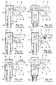
Afin de mieux saisir la structure de ce dispositif, ce dernier a été également représenté de façon très schématique aux figures 2a à 2f, dans ses positions caractéristiques de fonctionnement.In order to better understand the structure of this device, the latter was also represented in a very schematic in Figures 2a to 2f, in its positions operating characteristics.
Ce dispositif D comporte un levier 1 qui peut pivoter
et qui est prévu pour coopérer avec un bec 2 monté sur un
barillet 4. Le levier 1 peut, en outre, coopérer avec un
goujon G solidaire du bloc de verrouillage PV qui, dans la
position montrée à la figure 2a, se trouve en position
haute de blocage de la barre B. On notera que le bloc de
verrouillage PV est maintenu dans cette position par un
ressort de compression R qui est supporté par une tige TG
pilotée par l'ensemble moteur EM (figure 1).This device D comprises a
Dans cette position normale de fonctionnement, le bloc de verrouillage PV empêche le déplacement de la barre B, si bien que la porte de l'enceinte ne pas être ouverte.In this normal operating position, the PV locking block prevents the bar from moving B, so that the enclosure door cannot be opened.
Comme on le voit à la figure 2b, le bloc PV peut être amené vers le bas, par l'abaissement de la tige TG (flèche F1), sous l'action de l'ensemble moteur EM, pour dégager le chemin de la barre B et permettre l' ouverture de la porte. Dans cette position basse du bloc PV, la barre B peut être reculée (flèche F2), afin de dégager les pênes PT de la tringlerie TR.As seen in Figure 2b, the PV block can be brought down, by lowering the TG rod (arrow F1), under the action of the EM motor assembly, to release the path of the bar B and allow the opening of the door. In this low position of the PV block, the bar B can be moved back (arrow F2), in order to release the bolts PT of linkage TR.
On voit donc que dans ce mode de fonctionnement, le
levier 1 et le barillet 4 ne sont pas opérants et qu'ils
n'influent pas sur le fonctionnement normal de la serrure
horaire SH.We therefore see that in this operating mode, the
Le barillet 4 porte une goupille 6 qui est associée à
un autre ressort de compression précontraint, non
représenté; cet ensemble étant logé dans un trou borgne
ménagé dans le barillet 4.The
En cas de panne, un circuit électronique CE qui est
associé à un ensemble de capteurs, détecte la panne et
commande un deuxième ensemble moteur, non représenté, qui
entraíne le barillet 4 en rotation (figure 2c, flèche F3),
par l'intermédiaire d'un rouage et d'un ressort (non
représentés), ce ressort étant prévu pour emmagasiner
l'énergie d'entraínement fournie par cet ensemble moteur.In the event of a fault, a CE electronic circuit which is
associated with a set of sensors, detects the failure and
controls a second motor assembly, not shown, which
drives the
Si la barre B se trouve en position d'aboutement
contre le bloc de verrouillage PV (fig. 2c), le bec 2
vient alors buter contre la barre B, le ressort qui
entraíne le barillet 4 absorbant alors l'énergie
d'entraínement fournie par l'ensemble moteur
correspondant.If the bar B is in the abutment position
against the PV locking block (fig. 2c), the
Si après ouverture de la serrure S, l'opérateur
constate le dysfonctionnement de la serrure horaire SH, il
déplace la barre B vers sa position de verrouillage, via
le volant de commande (fig. 2d, flèche F4). Le barillet 4
peut alors continuer sa rotation (flèche F5) pour venir
s'arrêter contre une butée fixe 8.If after opening the lock S, the operator
notes the malfunction of the SH time lock, it
moves bar B to its locked position, via
the control wheel (fig. 2d, arrow F4).
Dans cette position, la goupille 6 vient s'engager
dans une creusure 9 ménagée dans le levier 1, ce qui relie
mécaniquement et de façon irréversible le barillet 4 au
levier 1.In this position, the
Le bec 2 se trouvant dans cette position désormais
sur le chemin de la barre B, l'opérateur en reculant cette
barre (figures 2e et 2f, flèche F6) vient pousser le bec 2
qui provoque la rotation du barillet 4.The
Ainsi, le barillet 4 qui est désormais lié en
rotation au levier 1 via l'engagement de la goupille 6
dans la creusure 9, fait pivoter le levier 1 qui vient
pousser le goujon G du bloc de verrouillage PV (fig. 2e),
à l'encontre de l'effet du ressort R. En effet, on
comprend que du fait de l'état de dysfonctionnement, la
tige TG est restée en position haute et continue de
solliciter le ressort R contre le bloc de verrouillage PV.
Le levier 1 vient donc s'opposer à l'effet de poussée du
ressort R, qui se comprime.Thus,
Ainsi, en continuant de déplacer la barre B vers sa position de déverrouillage, l'opérateur peut provoquer le dégagement du bloc PV en l'escamotant complètement, grâce au levier 1 (fig. 2f, flèche F7). La porte peut donc être ouverte.So, by continuing to move the bar B towards its unlocking position, the operator can cause the release of the PV block by completely retracting it, thanks lever 1 (fig. 2f, arrow F7). The door can therefore be opened.
Ce dispositif permet d'atteindre le résultat souhaité.This device achieves the result wish.
Toutefois, il présente plusieurs inconvénients.However, it has several drawbacks.
En effet, pour mettre de nouveau la serrure horaire
SH et le dispositif D en service, il faut désolidariser le
barillet 4 du levier 1 et ramener le levier 1 dans sa
position initiale de repos. Cette opération nécessite
d'ouvrir la serrure et requiert l'intervention d'un
spécialiste, intervention qui peut requérir plusieurs
jours. Pendant ce temps, la serrure horaire est hors
service. Indeed, to put the time lock again
SH and device D in service, it is necessary to separate the
En outre, étant donné que c'est le mouvement de la barre B qui permet de "forcer" l'ouverture de la serrure, il faut prévoir des lots distincts de serrures adaptées, soit à des portes à ouverture à gauche (configuration représentée aux figures 2a à 2f), soit à des portes à ouverture à droite (configuration symétrique, non représentée). Cette condition impose donc une fabrication, un montage, une gestion et une logistique de deux types de serrure, ce qui augmente les coûts de revient de serrures.Furthermore, since it is the movement of the bar B which makes it possible to "force" the opening of the lock, separate batches of suitable locks must be provided, either to left-opening doors (configuration shown in Figures 2a to 2f), either at doors to right opening (symmetrical configuration, no shown). This condition therefore requires manufacturing, assembly, management and logistics of two types of lock, which increases the cost price of locks.
En outre, ces serrures doivent faire l'objet d'un
ajustement très précis au montage, puisque la barre B doit
impérativement venir au contact du bec 2, pour assurer le
bon fonctionnement de l'ouverture de secours.In addition, these locks must be subject to a
very precise adjustment during assembly, since bar B must
imperatively come into contact with
Par ailleurs, les pièces qui constituent le dispositif d'annulation D doivent être de haute qualité. Elle doivent en effet être en mesure de vaincre l'effort de poussée du ressort de compression R qui tend à maintenir le bloc de verrouillage PV dans sa position haute.Furthermore, the parts which constitute the D cancellation device must be of high quality. They must indeed be able to overcome the effort compression spring R which tends to hold the PV locking block in its position high.
Par conséquent, ce dispositif met en oeuvre un nombre important de pièces qui sont délicates à réaliser et à ajuster, si bien qu'il est relativement peu économique.Therefore, this device implements a number important parts that are difficult to produce and adjust, so it is relatively uneconomical.
La présente invention a pour but de remédier à ces inconvénients en fournissant un dispositif pouvant être remis en état de fonctionnement et réarmé simplement et rapidement, sans l'intervention d'un spécialiste, et sans ouverture ni démontage de la serrure.The object of the present invention is to remedy these disadvantages in providing a device that can be simply restored to working order and reset quickly, without the intervention of a specialist, and without opening or dismantling the lock.
La présente invention a également pour but de fournir un dispositif à haut niveau de fiabilité, de conception simple et peu coûteux, permettant à la serrure horaire qui en est équipée de se monter indifféremment sur des portes à ouvertures à droite ou à ouverture à gauche.The present invention also aims to provide a device with a high level of reliability, of design simple and inexpensive, allowing the time lock which is equipped with it to be mounted indifferently on doors with right openings or left openings.
A cet effet, l'invention a pour objet un dispositif pour annuler, notamment en cas de panne, l'interdiction d'ouverture d'une serrure à ouverture conditionnelle, ce dispositif comprenant:
- des moyens moteur,
- un organe de transmission,
- un bloc de verrouillage lié aux moyens moteur via l'organe de transmission et pouvant être actionné par les moyens moteur pour occuper une position active dans laquelle ce bloc s'oppose au déplacement d'une barre, et une position inactive dans laquelle ledit bloc autorise le déplacement de cette barre, ce dispositif étant caractérisé en ce qu'il comprend des moyens de désactivation prévus pour rendre libre l'organe de transmission et pour autoriser le dégagement du bloc de verrouillage en dehors de sa position active.
- motor means,
- a transmission organ,
- a locking block linked to the motor means via the transmission member and capable of being actuated by the motor means to occupy an active position in which this block is opposed to the movement of a bar, and an inactive position in which said block authorizes the movement of this bar, this device being characterized in that it comprises deactivation means provided for making the transmission member free and for authorizing the release of the locking block outside of its active position.
Mais d'autres caractéristiques et avantages de l'invention apparaítront à la lecture de la description détaillée qui suit, faite en référence aux dessins annexés qui sont donnés uniquement à titre d'exemple, et dans lesquels:
- la figure 1 est une représentation très schématique d'un ensemble de sécurité classique auquel peut être incorporé un dispositif d'annulation et une serrure à ouverture conditionnelle, selon l'invention;
- les figures 2a à 2f représentent dans différents stades de fonctionnement un dispositif d'annulation de structure classique, et qui a été décrit de façon détaillée ci-avant;
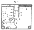
- la figure 3a est une vue de face d'un dispositif selon l'invention, incorporé dans le bâti d'une serrure horaire et représenté dans une première position caractéristique de fonctionnement;
- la figure 3b est une vue de derrière du dispositif de la figure 3a, montré dans la même position;
- la figure 3c est une vue en coupe du dispositif selon l'invention faite selon la ligne C-C de la figure 3b;
- la figure 3d est une vue en coupe du dispositif selon l'invention faite selon la ligne D-D de la figure 3b;
- les figures 4a à 4c, 5a à 5c et 6a à 6c sont des vues similaires aux figures 3a à 3c, mais représentant le dispositif selon l'invention dans d'autres positions caractéristiques de fonctionnement; et
- la figure 4d est une vue en perspective d'un ressort pince équipant le dispositif selon l'invention.
- Figure 1 is a very schematic representation of a conventional security assembly which can be incorporated a cancellation device and a lock with conditional opening, according to the invention;
- FIGS. 2a to 2f show in different stages of operation a device for canceling a conventional structure, and which has been described in detail above;
- Figure 3a is a front view of a device according to the invention, incorporated in the frame of a time lock and shown in a first characteristic operating position;
- Figure 3b is a rear view of the device of Figure 3a, shown in the same position;
- Figure 3c is a sectional view of the device according to the invention taken along the line CC of Figure 3b;
- Figure 3d is a sectional view of the device according to the invention made along the line DD of Figure 3b;
- Figures 4a to 4c, 5a to 5c and 6a to 6c are views similar to Figures 3a to 3c, but showing the device according to the invention in other characteristic operating positions; and
- Figure 4d is a perspective view of a clamp spring fitted to the device according to the invention.
En se référant désormais aux figure 3a à 3d, on
décrira ci-après un mode de réalisation d'un dispositif
selon l'invention, repéré ici par la référence générale
10.Referring now to FIGS. 3a to 3d, we
will describe below an embodiment of a device
according to the invention, identified here by the
Le dispositif 10 selon l'invention est monté dans un
bâti 12 d'une serrure SHI qui est destinée à équiper un
ensemble de sécurité, tel que celui représenté à la figure
1.The
A ce titre, on comprendra de la description qui suit
que la serrure SHI en étant équipée du dispositif 10 se
trouve modifiée et très simplifiée.As such, the following description will be understood.
that the SHI lock being equipped with the
Ainsi, la serrure SHI selon l'invention est destinée à équiper un ensemble de sécurité du même type que celui qui a été décrit ci-avant.Thus, the SHI lock according to the invention is intended to equip a security system of the same type as that which has been described above.
La serrure SHI selon l'invention est donc également destinée à bloquer le déplacement d'une barre B vers sa position de déverrouillage, par exemple dans des plages horaires déterminées, dans lesquelles il a été décidé d'interdire l'ouverture de la porte PO (figure 1), dans les mêmes conditions que celles expliquées ci-avant.The SHI lock according to the invention is therefore also intended to block the movement of a bar B towards its unlock position, for example in ranges fixed times, in which it was decided to prohibit the opening of the PO door (figure 1), in the same conditions as those explained above.
L'invention est donc ici décrite dans son application à une serrure horaire, puisque les conditions d'ouverture et de fermeture de la porte sont fixées en fonction de plage horaire déterminées et programmées.The invention is therefore described here in its application to a time lock, since the opening conditions and closing the door are fixed according to time range determined and programmed.
On précisera que cette application n'est donnée ici qu'à titre d'exemple et que l'invention n'est pas limitée à cette application. L'invention peut également s'appliquer à d'autres types de serrure pour lesquelles les conditions d'ouverture et de fermeture sont liées à d'autres paramètres que le temps ou sont liées, pas uniquement à des paramètres de temps, mais aussi à des paramètres supplémentaires.Note that this application is not given here as an example and the invention is not limited to this application. The invention may also apply to other types of lock for which the opening and closing conditions are linked to other parameters than time or are related, not only to time parameters, but also to additional parameters.
Pour cette raison, la serrure SHI est qualifiée ici de façon générique de serrure à ouverture "conditionnelle".For this reason, the SHI lock is qualified here generically from opening lock "Conditional".
Toutefois, l'application à une serrure horaire constitue une application particulière et avantageuse qui constituera le mode de réalisation préféré auquel il sera fait référence dans cette description.However, applying to a time lock constitutes a particular and advantageous application which will be the preferred embodiment to which it will be refers in this description.
On comprend donc que le dispositif 10 permet de lever
et d'annuler une interdiction d'ouverture qui a été
imposée par cette serrure à ouverture conditionnelle. Le
dispositif 10. sera appelé dispositif "d'annulation".It is therefore understood that the
La serrure SHI comporte un bloc de verrouillage PVI
qui, dans cet exemple, est un bloc de forme
parallélépipèdique pouvant coulisser entre deux positions
caractéristiques respectivement haute et basse, en se
translatant dans un guide 14, formé de deux parois
parallèles 16 et 18.The SHI lock has a PVI locking block
which, in this example, is a shape block
rectangular that can slide between two positions
high and low characteristics respectively,
translating in a
Le bloc PVI est monté dans le guide 14 avec des jeux
de fonctionnement latéraux importants lui permettant de
coulisser; sans friction, entre ses deux positions.PVI block is mounted in
Le bloc PVI est représenté à la figure 3a dans une position basse dans laquelle il n'interfère pas avec le déplacement de la barre B de la tringlerie TR (ici non représentée).The PVI block is shown in Figure 3a in a low position in which it does not interfere with the displacement of bar B of linkage TR (here no shown).
Dans cette position, le bloc PVI repose contre une
butée 20 qui est constituée par des épaulements 22 formés
à la base des parois 16 et 18.In this position, the PVI block rests against a
La barre B, comme mentionné ci-avant, peut donc coulisser dans un couloir CR entre ses positions de verrouillage et de déverrouillage, sous la commande du volant VO (figure 1), afin de permettre l'ouverture ou la fermeture de la porte PO par le jeu des pênes PT de la tringlerie TR.Bar B, as mentioned above, can therefore slide in a CR corridor between its positions of locking and unlocking, under the control of the VO steering wheel (Figure 1), to allow opening or closing of the PO door by the set of bolts PT of the TR linkage.
Le bloc de verrouillage PVI est, dans cet exemple,
lié par une articulation classique, non représentée, à une
tige TGI qui est elle-même reliée, par une articulation
24, à une première extrémité 26a d'un bras de transmission
26 (figure 3b).The PVI locking block is, in this example,
linked by a classic joint, not shown, to a
TGI rod which is itself connected by a joint
24, at a
Le bras de transmission 26 est monté pivotant par une
deuxième extrémité 26b et il est couplé, au voisinage de
sa première extrémité 26a, à des moyens moteur MT.The
La tige TGI et le bras de transmission 26 constituent
un organe de transmission 28 qui relie, de façon
mécanique, le bloc de verrouillage PVI aux moyens moteur
MT et qui assure la transmission de l'énergie fournie par
les moyens moteur MT à ce bloc de verrouillage PVI.The TGI rod and the
Les moyens moteur MT comportent un moteur électrique
30 qui est alimenté et commandé par une unité électronique
de commande ELI (figure 1).The MV motor means include an
Le moteur 30 est monté sur une platine 32 qui est
agencée pour pouvoir être fixée, par exemple par des vis,
sur le bâti 12 de la serrure SHI.The
Dans cet exemple, le moteur 30 est monté sur la
platine 32 du côté opposé au bras de transmission 26. Ce
moteur 30 comporte un arbre moteur, non référencé, à
l'extrémité duquel est prévu un pignon d'entraínement 34
(figure 3d) qui débouche, par rapport à la platine 32, du
côté du bras 26, côté de la platine où se situent tous les
composants fonctionnels du dispositif, qui sont destinés à
coopérer et à se mettre en mouvement.In this example, the
Le pignon 34 engrène avec une roue d'entraínement 36
sur laquelle est ménagé un secteur denté en prise avec les
dents du pignon 34. Cette roue 36 est montée libre en
rotation sur un axe 38 (figure 3c) chassé dans la platine
32.The
La roue 36 comporte en outre un.méplat 40 sur lequel
frotte une lame 42 d'un capteur de position 44 capable de
fournir à l'unité électronique de commande ELI des signaux
représentatifs de la position angulaire de la roue 36. On
comprendra de la description qui suit que, dans un mode de
fonctionnement normal du dispositif 10 correspondant à
l'entraínement normal du bloc PVI, ces signaux sont
également représentatifs des positions haute et basse du
bloc PVI, positions dites respectivement active
(référencée P1, figure 4a) et inactive (référencée P2,
figure 3a).The
Le capteur de position 44 est, en tant que tel, un
capteur de structure classique et il ne sera pas décrit
ici de façon plus détaillée.The
La roue 36 comporte en outre une portée 46 qui
s'étend perpendiculairement depuis le corps ou planche de
la roue 36, et de façon coaxiale à son axe de rotation
géométrique X1.The
Cette portée 46 a une forme cylindrique allongée et
elle fait saillie du corps de la roue 36, en direction du
bâti 12. On notera que l'axe 38 qui supporte la roue 36 en
rotation traverse le corps de la roue 36 et s'étend sur la
longueur de la portée 46. On précisera aussi que la roue
36 et la portée 46 ne forment qu'une pièce, la portée 46
et le corps de la roue 36 venant de matière et étant
réalisées par exemple en matériau synthétique, tel que du
polyoxyméthylène que l'on désigne communément par
l'abréviation P.O.M.This
Un ressort 48, appelé ressort pince, est monté autour
de la portée 46. Ce ressort 48 a un corps 48c formé d'un
enroulement hélicoïdal ayant dans cet exemple plusieurs
spires, le corps 48c étant positionné librement autour de
la portée 46. Ce ressort 48 possède en outre deux bras
radiaux 50 et 51 qui sont prévus pour entraíner l'organe
de transmission 28, comme on le comprendra ci-après.A
Les deux bras 50 et le corps hélicoïdal 48c du
ressort 48 sont formés d'un même fil élastique F. Ce fil
peut absorber des contraintes de flexion et permet aux
deux bras 50 et 51 de s'ouvrir, dans certaines situations
d'entraínement du bloc PVI, puis de revenir dans leur
configuration d'origine, après déformation élastique.The two
Conformément à la représentation du dispositif sur
ces figures, et à la disposition superposée de ces deux
bras 50 et 51, ils sont désignés respectivement bras
supérieur et bras inférieur.In accordance with the representation of the device on
these figures, and the superimposed arrangement of these two
Le bras supérieur 50 est lié à une première spire 48a
du corps 48c (figures 3c et 4d), cette spire 48a reposant
latéralement contre la planche de la roue 36. La dernière
spire 48b se termine quant-à-elle au voisinage de
l'extrémité libre de la portée 46. Comme on le voit à la
figure 4d, le fil F qui constitue le ressort 48 présente
un bras de jonction 53 qui relie cette dernière spire 48b
au bras inférieur 51, et qui ramène ce fil F vers le bras
inférieur 51 en s'étendant le long du corps 48c.The
Ainsi, les deux bras 50 et 51 sont ramenés dans un
même plan sensiblement parallèle à la planche de la roue
36, par un retour du fil F.Thus, the two
On notera que les deux bras 50 et 51 s'étendent
radialement depuis la portée 46, dans des directions
sensiblement parallèles, vers un ergot 52 qui fait saillie
de la planche ou corps de la roue 36. L'ergot 52 est
positionné à une distance radiale de la portée 46 et de
l'axe de rotation X1 de ladite roue. L'ergot 52 peut donc
fournir un couple d'entraínement à l'organe de
transmission 28.Note that the two
Les deux bras 50 et 51 du ressort 48 s'étendent de
part et d'autre de cet ergot 52 et l'emprisonnent.The two
Dès lors, lorsque la roue 36 est entraínée en
rotation par le moteur 30, via le pignon 34, elle entraíne
avec elle le ressort 48 et plus particulièrement (en
fonctionnement normal) ses bras 50 et 51, l'ergot 52
poussant vers le haut ou vers le bas, dans le sens horaire
ou dans le sens anti-horaire, l'un ou l'autre des bras 50
et 51, selon le sens de rotation imprimé à ladite roue 36
par le moteur 30.Therefore, when the
Ainsi, la mise en rotation de la roue 36 sollicite
les bras 50 et 51 et provoque leurs déplacements
angulaires qui, en fonction normal, sont simultanés.Thus, the rotation of the
Le dispositif 10 selon l'invention comporte en outre
un doigt 54 (voir figure 6b) qui fait saillie,
parallèlement à l'ergot 52 et parallèlement à l'axe de
rotation X1 de la roue 36.The
Les deux bras 50 et 51 du ressort 48 s'étendent de
part et d'autre du doigt 54 et enserrent et emprisonnent
également ce doigt 54 tout comme l'ergot 52. Par
conséquent, tout déplacement en rotation de la roue 36
dans un sens ou dans un autre pousse le doigt 54 vers le
haut ou vers le bas, via l'ergot 52 et via les bras 50 et
51 du ressort 48. La rotation de la roue 36 a donc pour
fonction de provoquer, en mode de fonctionnement normal,
un mouvement de montée ou de descente du doigt 54, mais
avec interposition à ce niveau d'un organe élastique de
transmission de mouvement formé dans cet exemple par le
ressort pince 48.The two
Le doigt 54 est solidaire d'un bras oscillant 56 qui
a une forme générale correspondant sensiblement à celle du
bras de transmission 26 et qui est monté de façon
adjacente et juxtaposée à cet organe de transmission.The
Le bras oscillant 56, que l'on voit de façon plus
détaillée à la figure 6b, est formé comme le bras de
transmission 26 d'une plaque métallique emboutie de faible
épaisseur ayant en plan une forme de "J". Les coudes de
ces deux bras juxtaposés 26 et 56 permettent à ces bras,
lorsqu'ils sont en position haute, de venir au voisinage
de la roue 36 (voir figures 4b, 5b et 6b) et de porter
leurs extrémités libres au-dessus de la roue 36.The
Cette disposition fournit un agencement compact qui offre une amplitude de mouvement permettant d'amener le bloc B dans ses deux positions extrêmes P1 et P2.This arrangement provides a compact arrangement which provides range of motion to bring the block B in its two extreme positions P1 and P2.
Le doigt 54 est ménagé à une première extrémité libre
56a du bras oscillant 56 et, dans cet exemple, il vient
avantageusement de matière avec le bras 56.The
A sa deuxième extrémité 56b, le bras oscillant 56 est
monté libre en rotation autour d'une portée 58 qui fait
saillie de la platine 32 et qui est formée par une douille
chassée dans cette platine. Le bras oscillant 56 peut donc
pivoter librement autour d'un axe de rotation X2 (figure
3c) qui est parallèle à l'axe de rotation X1 de la roue
36.At its
De façon coaxiale à cet axe X2, est monté un deuxième
moteur électrique 60 (figure 3d) qui est également piloté
par l'unité de commande électronique ELI. Ce moteur 60 est
monté sur la platine 32 du même côté que le moteur 30. Ce
moteur 60 est lié mécaniquement en rotation à un arbre
d'entraínement 62 qui est guidé dans la douille 58 et qui
est positionné de façon coaxiale à l'axe de rotation X2.Coaxial with this axis X2, is mounted a second
electric motor 60 (figure 3d) which is also controlled
by the ELI electronic control unit. This
Comme on le voit sur les figures, les deux axes de rotation X1 et X2 sont positionnés dans un plan horizontal PH qui correspond ici au plan de la coupe C-C et qui est perpendiculaire à la direction de déplacement du bloc PVI.As can be seen in the figures, the two axes of rotation X1 and X2 are positioned in a horizontal plane PH which here corresponds to the plane of the section C-C and which is perpendicular to the direction of movement of the PVI block.
Un tenon à tête 64 est chassé dans l'arbre
d'entraínement 62. Le tenon 64 forme un axe de rotation
X3, ce tenon 64 et cet axe X3 étant positionnés sur
l'arbre 62 de telle sorte que l'axe X3 se trouve
latéralement décalé par rapport à l'axe de rotation X2. On
remarquera que, dans cet exemple, et dans ses deux
positions caractéristiques (figures 3b, 4b, 5b et 6b),
l'axe X3 s'étend également dans le plan PH.A 64 headed tenon is chased into the
Ainsi, on comprendra que le tenon 64 est excentré par
rapport à l'axe de rotation du moteur 60.Thus, it will be understood that the
Comme on le voit à la figure 3c, le tenon 64 supporte
et guide en rotation l'extrémité 26b du bras de
transmission 26. Le bras de transmission 26 peut donc
pivoter librement autour de ce tenon 64 et autour de l'axe
de rotation X3 qui constitue l'axe de rotation du bras de
transmission 26 et qui est par conséquent distinct, mais
voisin de l'axe de rotation X2 du bras oscillant 56. Dans
cette application, l'axe X2 est décalé dans le plan PH de
1 mm (10-3 Mètre) de l'axe X3.As can be seen in FIG. 3c, the
Ainsi, grâce à cette construction, l'extrémité 26b du
bras de transmission 26 et l'axe de rotation X3 de ce bras
peuvent être déplacés latéralement à gauche ou à droite,
pour occuper une première position dite d'enclenchement
représentée plus particulièrement aux figures 3a, 3b et
4a, 4b ou une deuxième position dite de déclenchement
représentée plus particulièrement aux figures 5a, 5b et
6a, 6b.Thus, thanks to this construction, the
Ce déplacement de l'extrémité 26b du bras de
transmission 26 et de son axe de rotation X3 est commandé
par le moteur électrique 60, grâce à la rotation de son
arbre 62. Le tenon 64 constitue donc, dans cet agencement,
un excentrique assurant des fonctions de débrayage et
d'embrayage de l'organe de transmission 28, fonctions que
l'on expliquera ci-après de façon plus détaillée.This displacement of the
Comme on le voit plus particulièrement à la figure
6b, le bras de transmission 26 comporte une encoche ou
rainure droite 66 qui est agencée (figure 3a) pour
recevoir le doigt 54.As seen more particularly in the figure
6b, the
L'encoche 66 est ménagée dans l'extrémité 26a du bras
26 et elle s'ouvre en direction de l'extrémité opposée 26b
de ce bras 26 et en direction du doigt 54. L'encoche ou
rainure 66 s'étend, dans une direction sensiblement
parallèle au plan PH.The
L'encoche 66 peut donc coulisser avec jeu sur le
doigt 54, en direction longitudinale, c'est-à-dire de la
gauche vers la droite et inversement. On comprend que ce
coulissement est piloté par l'excentrique 64 lors de la
mise en rotation de l'arbre du moteur 60, qui peut tirer
ou pousser le bras de transmission 26, soit pour amener
l'encoche 66 sur le doigt 54 et permettre leur engagement
(position tirée, figures 3a à 3d et 4a à 4c), soit pour
éloigner cette encoche 66 du doigt 54 et permettre leur
désengagement (position poussée, figures 5a à 5c et 6a à
6c).The
On comprend que l'engagement mécanique du doigt 54
dans l'encoche 66 assure l'entraínement du bras de
transmission 26 par le bras oscillant 56 qui constitue un
entraíneur de l'organe de transmission 28.We understand that the mechanical engagement of the
Le dispositif 10 selon l'invention comprend au moins
deux unités fonctionnelles caractéristiques, à savoir,
d'une part, les moyens moteurs MT, et, d'autre part,
l'organe de transmission 28.The
Dans cet exemple de réalisation, les moyens moteur MT
sont constitués par le moteur 30, le pignon 34, la roue
36, l'ergot 52, le ressort 48 et ses deux bras 50 et 51;
le bras oscillant 56 et son doigt 54 qui ont également une
fonction motrice étant couplés aux moyens moteur MT via le
ressort 48.In this embodiment, the motor means MT
consist of the
L'organe de transmission 28 est constitué quant-à-lui
de la tige TGI, de l'articulation 24 et du bras de
transmission 26. L'encoche 66 est donc ménagée sur
l'organe de transmission 28. On comprend donc que le bloc
de verrouillage PVI est lié aux moyens moteur MT par
l'intermédiaire de l'organe de transmission 28, via le
ressort 48 qui est interposé entre ces moyens moteur MT et
cet organe de transmission 28.The
Le dispositif 10 selon l'invention est représenté aux
figures 3a à 3d et 4a à 4c, dans une première
configuration caractéristique, dans laquelle l'encoche 66
est engagée sur doigt 54. Dans cette configuration,
l'arbre 62 est maintenu bloqué dans une position angulaire
déterminée par une butée non représentée, et le tenon ou
excentrique 64 est maintenu dans sa position de droite
dite d'enclenchement (figures 3a, 3b, 4a et 4b), le bras
de transmission 26 étant maintenu par cet excentrique en
position tirée.The
Ainsi, lorsque l'unité électronique ELI commande la
rotation du moteur 30, la roue 36 tourne dans le sens
horaire et le bras inférieur 51 du ressort 48 poussent le
doigt 54 qui déplace le bras oscillant 56, le bras de
transmission 26 et donc tout l'organe de transmission 28
vers le haut, pour monter le bloc de verrouillage dans sa
position active P1 (figures 4a à 4c) où il peut s'opposer
au déplacement de la barre B dans le couloir CR.When the ELI electronic unit controls the
rotation of the
Le capteur 44 renseigne l'unité électronique ELI qui
en déduit que le bloc PVI se trouve dans sa position
active. The
Lorsque le temps correspondant à l'interdiction
d'ouverture de la serrure SHI s'est écoulé, l'unité
électronique ELI commande la rotation du moteur 36 en sens
inverse qui ramène par les mêmes moyens le bloc PVI vers
le bas, en position inactive P2, le bloc venant reposer en
butée contre la butée 20.When the time corresponding to the ban
the SHI lock has opened, the unit
electronic ELI controls the rotation of the
Le capteur 44 renseigne de nouveau l'unité
électronique ELI qui en déduit que le bloc PVI se trouve
dans sa position inactive et que la barre B peut être
déplacée dans le couloir CR pour l'ouverture de la porte.
L'opérateur pourra donc à partir de ce moment ouvrir la porte PO (figure 1) à condition bien entendu qu'il possède la ou les autorisations nécessaires pour ordonner l'ouverture de la serrure S.The operator can therefore from this moment open the PO door (Figure 1) provided of course that has the necessary authorization (s) to order opening the lock S.
Si l'unité électronique ELI provoque au début d'une
plage horaire la montée du bloc PVI alors que la barre se
trouve au même moment dans le couloir CR au droit du guide
14 (la porte n'est donc pas encore verrouillée), le bloc
PVI va venir buter contre la barre B. Le moteur 30 va
cependant continuer sa rotation pour finir sa course de
commande et le ressort 48 va s'ouvrir par écartement
élastique de ses deux bras 50 et 51. L'information
ordonnant le déplacement du bloc PVI vers sa position
active P1 est "enregistrée" par le ressort 48. Le bloc PVI
finira sa course jusqu'à sa position active P1, sous
l'impulsion du ressort 48, lorsque la barre B aura été
translatée vers la droite, vers sa position de
verrouillage.If the ELI electronic unit causes at the start of a
time range the rise of the PVI block while the bar is
found at the same time in the corridor CR to the right of the guide
14 (the door is therefore not yet locked), the block
PVI will come up against
Le même type de procédure s'exécute si la barre B
coince le bloc PVI en position haute, alors que le moteur
30 a fait tourner la roue 36 dans le sens anti-horaire
pour permettre le retour du bloc PVI vers le bas.The same type of procedure is executed if the bar B
clamps the PVI block in the high position, while the
Les bras 50 et 51 du ressort 48 vont également
s'écarter tandis que la roue 36 finira sa course sous
l'impulsion du moteur 30. Lorsque la barre B sera déplacée
vers la droite, vers sa position de verrouillage, le bloc
PVI sera ramené vers le bas par l'action du ressort 48 et,
dans cet exemple, également par l'action combinée de la
gravité.The
Ainsi, on constate que dans cet agencement les moyens
moteur MT sont liés au bloc de verrouillage PVI par
l'intermédiaire du ressort 48 qui forme une liaison
élastique entre les moyens moteur MT et l'organe de
transmission 28.Thus, we see that in this arrangement the means
MV motor are linked to the PVI locking block by
through the
Si le capteur 44 informe l'unité électronique ELI que
le bloc de verrouillage PVI est en position active P1
(figures 4a à 4c), alors que la plage horaire
correspondant à l'interdiction d'ouverture de la serrure
est dépassée, l'unité électronique ELI ou un autre agent
constate alors qu'il y a panne ou dysfonctionnement.If the
Dans ces conditions, l'unité électronique de commande
ELI ordonne la rotation du moteur 60 qui va commander le
déplacement de l'excentrique 64. Cet excentrique 64 va
déplacer l'axe de rotation X3 du bras de transmission 26
vers la gauche et il va, par conséquent, pousser le bras
de transmission 26 vers l'avant. Cette configuration est
représentée aux figure 5b à 5c.Under these conditions, the electronic control unit
ELI orders the rotation of the
On remarquera que l'encoche 66 est ménagée, grâce à
une longueur appropriée de son bord supérieur 66a, de
sorte que, lorsque le bras 26 a parcouru sa course de
déclenchement, le doigt 54 sorte complètement de l'encoche
66. Il s'opère donc, via la commande du moteur 60, un
débrayage de l'organe de transmission 28 vis-à-vis des
moyens moteur MT.It will be noted that the
Par conséquent, et comme on le voit plus
particulièrement à la figure 6b, l'organe de transmission
28 et en particulier le bras de transmission 26 sont alors
libérés de leur accouplement avec les moyens moteur MT et
permettent, dans cet exemple par simple effet de la
gravité, le retour du bloc de verrouillage PVI dans sa
position inactive P2.Therefore, and as we see more
particularly in Figure 6b, the
La barre B peut être déplacée et la porte PO peut donc être ouverte (figure 6a). Bar B can be moved and door PO can therefore be open (Figure 6a).
Dès lors, on comprend de cette description que l'on a
fourni par cet agencement, des moyens de désactivation qui
sont ménagés pour rendre libre l'organe de transmission 28
en cas de dysfonctionnement, ces moyens autorisant dans
cette situation d'exception le dégagement du bloc de
verrouillage PVI en dehors de sa position active P1.Therefore, we understand from this description that we have
provided by this arrangement, deactivation means which
are arranged to make the
L'organe de transmission 28 est donc rendu inopérant
puisque, soudainement, il n'a plus de liaison mécanique
avec les moyens moteur MT qui n'exercent plus aucune
contrainte ni sur cet organe, ni sur le bloc PVI.The
Aussi, les moyens de désactivation sont prévus pour
rompre purement et simplement l'accouplement mécanique
entre les moyens moteur MT et le bloc de verrouillage PVI,
en provoquant le dégagement de l'encoche 66 et du doigt
54, ce qui permet au bloc de verrouillage PVI de revenir
librement vers sa position inactive P2, dans cet exemple
par l'action seule de la gravité. On constate que l'organe
de transmission 28 pivote alors librement sur la platine
32.Also, the deactivation means are provided for
purely and simply break the mechanical coupling
between the motor means MT and the PVI locking block,
by causing the release of the
Plus particulièrement, les moyens de désactivation
sont constitués par des moyens de débrayage qui peuvent
découpler, sur commande, l'organe de transmission 28 des
moyens moteurs MT, ces moyens étant constitués par
l'encoche 66 et le doigt 54 et par la disposition de l'un
sur l'organe de transmission 28 et par l'accouplement de
l'autre avec les moyens moteur MT.More specifically, the means of deactivation
are constituted by declutching means which can
decoupled, on command, the
Par ailleurs, on comprendra que ces moyens de
débrayage comportent en outre des moyens de déclenchement
qui sont constitués par l'excentrique 64 et qui agissent
sur l'engagement du doigt 54 dans l'encoche 66 pour
découpler l'organe de transmission 28 des moyens moteur
MT. Plus particulièrement, ces moyens de débrayage
provoquent le déplacement de l'encoche 66 par rapport au
doigt 54, les moyens de déclenchement agissant ouvertement
sur l'organe de transmission 28, en le déplaçant par
rapport au doigt 54, c'est-à-dire par rapport au bras
oscillant ou entraíneur 56. Furthermore, it will be understood that these means of
declutching further comprise triggering means
which consist of the eccentric 64 and which act
on the engagement of the
Pour permettre la remise en service du dispositif 10
et de la serrure SHI et pour réarmer ce dispositif, on
commande, via l'unité électronique ELI, la rotation du
moteur 30 et en particulier la rotation de la roue 36 dans
le sens anti-horaire. Le bras oscillant ou entraíneur 56
est abaissé jusqu'à ce que le doigt 54 vienne buter contre
un bord inférieur 66b de l'encoche 66, bord qui est de
longueur supérieure à celle du bord supérieur 66a.To allow the device to be put back into
Le doigt 54 se trouve en position pour pouvoir être
de nouveau engagé dans l'encoche 66. A ce moment, on
pilote le moteur 60 pour tirer le bras de transmission 26
et pour réengager l'encoche 66 sur le doigt 54. Le
dispositif 10 est donc réarmé et la serrure peut
fonctionner sans avoir été ouverte. On notera que ces
opérations se faisant via des moyens électromécaniques,
elles peuvent être pilotées intégralement par l'unité
électronique ELI qui peut être elle même gérée à distance,
par exemple par communication téléphonique, depuis un
centre de surveillance.
Aussi et de façon avantageuse, l'invention comporte
donc des moyens d'activation prévus pour rendre, sur
commande, l'organe de transmission 28 de nouveau opérant,
après qu'il ait été rendu libre précédemment par les
moyens de désactivation, afin de permettre au bloc de
verrouillage PVI d'occuper à nouveau sa position active
P1, en étant actionné par les moyens moteur MT. Ces moyens
d'activation sont en effet prévus pour rétablir
l'accouplement mécanique entre les moyens moteur MT et le
bloc de verrouillage PVI, après que cet accouplement ait
été rompu par les moyens de désactivation. On précisera
aussi que les moyens d'activation sont constitués par des
moyens d'embrayage qui sont capables de coupler, sur
commande, l'organe de transmission 28 et les moyens moteur
MT, après rupture dudit accouplement, ces moyens
d'embrayage étant constitués par l'encoche 66 et le doigt
54 qui peut être ramené dans l'encoche 66 par des moyens
d'enclenchement pouvant en particulier réengager le doigt
54 dans ladite encoche 66 afin d'accoupler à nouveau
l'organe de transmission 28 et les moyens moteurs MT.Also and advantageously, the invention comprises
therefore activation means provided to make, on
control, the
Aussi, les moyens d'enclenchement sont prévus pour
agir sur l'organe de transmission 28, en le déplaçant par
rapport au doigt 54, ces moyens d'enclenchement étant
constitués par l'excentrique 64 et le système
d'entraínement 60 qui, en faisant tourner l'excentrique,
provoque le déplacement de l'organe de transmission 28
pour à nouveau engager l'encoche 66 sur le doigt 54.Also, the engagement means are provided for
act on the
On comprend de ce qui vient d'être décrit que dans
cet agencement le dispositif d'annulation 10 et les moyens
moteur MT qui assurent normalement la montée et la
descente du bloc PVI, sont associés fonctionnellement et
structurellement, en étant monté sur une même platine.
Plus particulièrement, les moyens de desactivation et
d'activation, les moyens de débrayage et les moyens
d'embrayage et les moyens de déclenchement et
d'enclenchement sont intégrés dans un même bloc, c'est-à-dire
sur la platine.We understand from what has just been described that in
this arrangement the
Claims (25)
- Device for lifting, in particular in the event of a breakdown or failure, the ban on the opening of a conditional opening locking system, this device including:driving means (MT),a transmission member (28),a blocking member (PVI) connected to the driving means (MT) via the transmission member (28) and able to be actuated by the driving means (MT) to occupy an active position (P1) in which said member opposes the movement of a bar (B), and an inactive position (P2) in which said member authorises the movement thereof, said device being characterised in that it includes de-activation means (54, 64, 66) provided for freeing the transmission member (28) and authorising the release of the blocking member (PVI) from its active position (P1).
- Device according to claim 1, characterised in that the de-activation means (54, 64, 66) are provided for interrupting the mechanical coupling between the driving means (MT) and the blocking member (PVI).
- Device according to claim 1 or 2, characterised in that the de-activation means (54, 64, 66) are provided for allowing the blocking member (PVI) to return freely to its inactive position (P2) by the action of gravity.
- Device according to any of claims 1 to 3, characterised in that the de-activation means (54, 64, 66) include disengaging means provided for uncoupling, on demand, the transmission member (28) from the driving means (MT).
- Device according to claim 4, characterised in that the disengaging means include a notch (66) and a finger (54) one of which is provided on the transmission member (28) while the other is coupled to the driving means (MT), the finger (54) being engaged in the notch (66) for driving the transmission member (28) by the driving means (MT).
- Device according to claim 5, characterised in that the disengaging means further include triggering means (64) acting on the engagement of the finger (54) in the notch (66), these means (64) being provided for interrupting the engagement of the finger (54) in the notch (66) and for uncoupling the transmission member (28) from the driving means (MT).
- Device according to claim 6, characterised in that the disengaging means (64) are provided for causing the movement of the notch (66) with respect to the finger (54).
- Device according to any of claims 5 to 7, characterised in that the notch (66) is arranged on the transmission member (28).
- Device according to any of claims 6 to 8, characterised in that the disengaging means (64) are provided for acting on the transmission member (28) by moving it with respect to the finger (54).
- Device according to any of claims 6 to 9, characterised in that the disengaging means (64) are formed by an eccentric member which has an axis (X3) with respect to which the transmission member (28) is rotatably mounted.
- Device according to claim 10, characterised in that said eccentric member is coupled to a driving system (60), which, by rotating the eccentric member, moves the position of the axis and causes the movement of the transmission member (28) to release the notch (66) from the finger (54).
- Device according to claim 11, characterised in that said driving system (60) is formed by an electric motor.
- Device according to any of the preceding claims, characterised in that it further includes activation means (54, 64, 66, MT) provided for making the transmission member (28) operative, on demand, after it has been freed by the de-activation means (54, 64, 66), in order to allow the blocking member (PVI) to occupy its active position (P1) again, by being actuated by the driving means (MT).
- Device according to claims 2 and 13, characterised in that the activation means (54, 64, 66, MT) are provided for re-establishing the mechanical coupling between the driving means (MT) and the blocking member (PVI), after said coupling has been interrupted by the de-activation means (54, 64, 66).
- Device according to claims 4 and 14, characterised in that the activation means (54, 64, 66, MT) include engaging means provided for coupling, on demand, the transmission member (28) and the driving means (MT), after said coupling has been interrupted.
- Device according to claims 5 and 15, characterised in that the engaging means are formed by the notch (66) and the finger (54) which can be brought back into the notch (66) by the engaging means (64) able to re-engage said finger (54) in said notch (66) in order to couple the transmission member (28) and the driving means (MT) again.
- Device according to claim 16, characterised in that the engaging means (64) are provided for acting on the transmission member (28), by moving it with respect to the finger (54).
- Device according to claims 11 and 16, characterised in that the engaging means (64) are formed by the eccentric member and the driving system (60) which, by rotating the eccentric member, causes the movement of the transmission member (28) to re-engage the notch (66) on the finger (54).
- Device according to any of the preceding claims, characterised in that the driving means (MT) are connected to the blocking member (PVI) via a spring (48) assuring an elastic connection between the driving means (MT) and the transmission member (28).
- Device according to claim 19, characterised in that the spring (48) is formed by a helical spring positioned around a sleeve (46) of the driving means (MT) and including two radial arms (50, 51) provided for driving the transmission member (28).
- Device according to claims 5 and 20, characterised in that the arms of the spring (48) confine the finger (54).
- Device according to any of claims 19 to 21, characterised in that the driving means (MT) include a catch (52) allowing the spring (48) to be driven in rotation by the driving means (MT).
- Device according to claim 10, characterised in that it includes an oscillating arm (56) rotatably mounted and carrying the finger (54), said arm (56) being mounted adjacent to the transmission member (28).
- Device according to any of the preceding claims, characterised in that it includes a stop (20) which is provided for limiting the movement of the blocking member (PVI) in its inactive position (P2).
- Application of the device according to any of the preceding claims to a conditional opening locking system.
Priority Applications (7)
| Application Number | Priority Date | Filing Date | Title |
|---|---|---|---|
| DE69726843T DE69726843D1 (en) | 1997-05-30 | 1997-05-30 | Device for releasing the opening lock of a lock that can be operated to a limited extent |
| EP97108690A EP0887496B1 (en) | 1997-05-30 | 1997-05-30 | Device to remove the barring mechanism of a preset opening lock |
| AT97108690T ATE256807T1 (en) | 1997-05-30 | 1997-05-30 | DEVICE FOR CANCELING THE OPENING LOCK OF A CONDITIONALLY OPERABLE LOCK |
| US09/084,984 US6032499A (en) | 1997-05-30 | 1998-05-28 | Device for lifting a ban on the opening of a conditional locking system |
| CA002239000A CA2239000A1 (en) | 1997-05-30 | 1998-05-28 | Device for lifting a ban on the opening of a conditional opening locking system |
| BR9806496-7A BR9806496A (en) | 1997-05-30 | 1998-05-29 | Locking suspension device when opening a conditional opening closing system. |
| ARP980102543A AR012892A1 (en) | 1997-05-30 | 1998-05-29 | DEVICE TO LIFT A PROHIBITION ON THE OPENING OF A CONDITIONAL OPENING LOCKING PROVISION |
Applications Claiming Priority (1)
| Application Number | Priority Date | Filing Date | Title |
|---|---|---|---|
| EP97108690A EP0887496B1 (en) | 1997-05-30 | 1997-05-30 | Device to remove the barring mechanism of a preset opening lock |
Publications (2)
| Publication Number | Publication Date |
|---|---|
| EP0887496A1 EP0887496A1 (en) | 1998-12-30 |
| EP0887496B1 true EP0887496B1 (en) | 2003-12-17 |
Family
ID=8226847
Family Applications (1)
| Application Number | Title | Priority Date | Filing Date |
|---|---|---|---|
| EP97108690A Expired - Lifetime EP0887496B1 (en) | 1997-05-30 | 1997-05-30 | Device to remove the barring mechanism of a preset opening lock |
Country Status (7)
| Country | Link |
|---|---|
| US (1) | US6032499A (en) |
| EP (1) | EP0887496B1 (en) |
| AR (1) | AR012892A1 (en) |
| AT (1) | ATE256807T1 (en) |
| BR (1) | BR9806496A (en) |
| CA (1) | CA2239000A1 (en) |
| DE (1) | DE69726843D1 (en) |
Families Citing this family (12)
| Publication number | Priority date | Publication date | Assignee | Title |
|---|---|---|---|---|
| US6006561A (en) * | 1997-05-07 | 1999-12-28 | Mas-Hamilton Group, Inc. | Electronic reset for solenoid activated control in an electronic lock |
| EP0881346A1 (en) * | 1997-05-30 | 1998-12-02 | Ilco-Unican S.A./Relhor Division | Engagement device for locking and unlocking a preset opening lock |
| DE19832516A1 (en) * | 1998-07-20 | 2000-01-27 | Schulte Schlagbaum Ag | Lock, especially for a locking system |
| ES2262271T3 (en) | 1999-07-12 | 2006-11-16 | Kaba Ag | MOTORIZED SECURITY LOCK. |
| US6449995B1 (en) * | 2000-03-09 | 2002-09-17 | International Business Machines Corp. | Automatic deadbolt |
| US20050193932A1 (en) * | 2004-03-05 | 2005-09-08 | Triteq Lock And Security, L.L.C. | Safe lock with motor controlled bolts and electronic access |
| US7464570B1 (en) * | 2008-02-26 | 2008-12-16 | Co-Young International Co., Ltd. | Time programmable unlocking lock |
| US20100269553A1 (en) * | 2009-04-24 | 2010-10-28 | Min Zhong | Double lock system |
| CN104652946A (en) * | 2015-01-05 | 2015-05-27 | 黑龙江大学 | Electronic lock alarm system with time recognition function and alarming method thereof |
| RU2672838C1 (en) * | 2018-06-22 | 2018-11-19 | Сергей Григорьевич Кузовников | Safe |
| CN109898927B (en) * | 2019-03-13 | 2022-01-28 | 浙江科熊智能科技有限公司 | Electronic anti-theft lock |
| CN113417517B (en) * | 2021-07-19 | 2022-09-20 | 任丘市恒威通信设备有限公司 | Intelligent coded lock for communication equipment |
Family Cites Families (15)
| Publication number | Priority date | Publication date | Assignee | Title |
|---|---|---|---|---|
| US2073523A (en) * | 1935-06-24 | 1937-03-09 | Charles F Meilink | Time control for repositories |
| US2191694A (en) * | 1939-04-27 | 1940-02-27 | Mosler Lock Company | Nonlockout combination time delay lock |
| US3576119A (en) * | 1968-11-25 | 1971-04-27 | Archie H Harris | Electromechanical door lock system |
| US3881171A (en) * | 1973-12-03 | 1975-04-29 | Mosler Safe Co | Vault protected with electronic time and combination lock |
| US3950678A (en) * | 1975-02-14 | 1976-04-13 | Kenyon Edwin Brewer | Timelock for bank vault doors and the like |
| DE2634107C3 (en) * | 1976-07-29 | 1982-01-14 | Theodor Kromer GmbH & Co KG Spezialfabrik für Sicherheitsschlösser, 7801 Umkirch | Time lock |
| US4634846A (en) * | 1984-05-22 | 1987-01-06 | American District Telegraph Company | Multimode programmable stand-alone access control system |
| US4633687A (en) * | 1985-01-22 | 1987-01-06 | Ni Industries, Inc. | Drive mechanism for key operated electronic lock |
| CH664794A5 (en) * | 1985-03-29 | 1988-03-31 | Relhor Sa | DEVICE FOR LIFTING A CONDITIONAL PROHIBITION OF THE OPERATION OF A LOCK. |
| FR2603059B1 (en) * | 1986-08-20 | 1988-11-18 | Relhor Sa | DEVICE FOR CANCELING THE PROHIBITION OF OPENING A LOCK WITH CONDITIONAL OPENING IN THE EVENT OF A BREAKDOWN |
| DE8914267U1 (en) * | 1989-10-27 | 1990-04-12 | Ikon Ag Praezisionstechnik, 1000 Berlin, De | |
| FR2661938A1 (en) * | 1990-05-14 | 1991-11-15 | Ciposa Microtech | DEVICE FOR CONTROLLING THE TIMED OPENING OF A LOCK. |
| US4977765A (en) * | 1990-06-04 | 1990-12-18 | Claude Legault | Delay action electronic timer lock with automatic cancellation cam |
| JP3167862B2 (en) * | 1994-06-30 | 2001-05-21 | 三井金属鉱業株式会社 | Door lock device with anti-theft mechanism |
| CH690502A5 (en) * | 1995-04-28 | 2000-09-29 | Relhor Sa | Programmable operational system for locking / unlocking a timed safety device. |
-
1997
- 1997-05-30 AT AT97108690T patent/ATE256807T1/en not_active IP Right Cessation
- 1997-05-30 DE DE69726843T patent/DE69726843D1/en not_active Expired - Lifetime
- 1997-05-30 EP EP97108690A patent/EP0887496B1/en not_active Expired - Lifetime
-
1998
- 1998-05-28 CA CA002239000A patent/CA2239000A1/en not_active Abandoned
- 1998-05-28 US US09/084,984 patent/US6032499A/en not_active Expired - Fee Related
- 1998-05-29 BR BR9806496-7A patent/BR9806496A/en not_active Application Discontinuation
- 1998-05-29 AR ARP980102543A patent/AR012892A1/en unknown
Also Published As
| Publication number | Publication date |
|---|---|
| BR9806496A (en) | 1999-12-28 |
| AR012892A1 (en) | 2000-11-22 |
| US6032499A (en) | 2000-03-07 |
| ATE256807T1 (en) | 2004-01-15 |
| DE69726843D1 (en) | 2004-01-29 |
| EP0887496A1 (en) | 1998-12-30 |
| CA2239000A1 (en) | 1998-11-30 |
Similar Documents
| Publication | Publication Date | Title |
|---|---|---|
| EP0959206B1 (en) | Motor vehicle door lock with electrical locking | |
| EP0887496B1 (en) | Device to remove the barring mechanism of a preset opening lock | |
| EP1069264B1 (en) | Motorized safety lock | |
| EP0903457B1 (en) | Electric lock for a vehicle door | |
| EP3581742B1 (en) | Door flush handle and method of operating the same | |
| FR2783860A1 (en) | DEVICE FOR ACTUATION BY ELECTRIC MOTOR OR ASSISTED BY ELECTRIC MOTOR OF A REAR TAILGATE OR OF A CLOSING DEVICE | |
| EP0953094B1 (en) | Mortise lock | |
| FR2652375A1 (en) | Safety lock | |
| FR2576961A1 (en) | MECHANISM FOR ASSISTING THE CLOSURE OF A DOOR OF A MOTOR VEHICLE | |
| EP0015857B1 (en) | Device for the motorized opening and closing of a gate | |
| EP0256430A1 (en) | Device for cancelling the preset barring of operating a lock in case of failure | |
| EP2367190B1 (en) | Locking device designed to prevent the earthing of an electrical protection device, and the electrical protection device including said device | |
| EP0991833B1 (en) | Driving device for locking and unlocking a lock with conditional opening | |
| EP2063053B1 (en) | Espagnolette or espagnolette-lock | |
| EP0748916B1 (en) | Actuator for a gate or other closure panel | |
| EP3808925B1 (en) | Lock for a door of a motor vehicle | |
| EP2045420A1 (en) | Handle system, in particular of an espagnolette, designed to be installed on the external surface of a door, such as the door of a refrigerated truck | |
| EP3032010B1 (en) | Lock for a door of a motor vehicle | |
| FR3111371A1 (en) | Electric locking mechanism for an opening including a mechanical emergency function | |
| EP1908901B1 (en) | Lock bar designed for opening and closing a door | |
| FR2944826A1 (en) | LOCKING LOCKING PEN LOCK BY KNEE | |
| EP1525369B1 (en) | Automatic device for stopping a power-driven curtain | |
| EP1320653A1 (en) | Closure system for mobile protecting system | |
| EP0927807A2 (en) | Means for opening/closing of a wing of a door, a shutter or simular | |
| FR2675458A1 (en) | Theft deterrent, particularly for a cycle |
Legal Events
| Date | Code | Title | Description |
|---|---|---|---|
| PUAI | Public reference made under article 153(3) epc to a published international application that has entered the european phase |
Free format text: ORIGINAL CODE: 0009012 |
|
| AK | Designated contracting states |
Kind code of ref document: A1 Designated state(s): AT BE CH DE ES FR GB IT LI LU NL SE |
|
| 17P | Request for examination filed |
Effective date: 19990630 |
|
| AKX | Designation fees paid |
Free format text: AT BE CH DE ES FR GB IT LI LU NL SE |
|
| GRAH | Despatch of communication of intention to grant a patent |
Free format text: ORIGINAL CODE: EPIDOS IGRA |
|
| GRAS | Grant fee paid |
Free format text: ORIGINAL CODE: EPIDOSNIGR3 |
|
| GRAA | (expected) grant |
Free format text: ORIGINAL CODE: 0009210 |
|
| AK | Designated contracting states |
Kind code of ref document: B1 Designated state(s): AT BE CH DE ES FR GB IT LI LU NL SE |
|
| PG25 | Lapsed in a contracting state [announced via postgrant information from national office to epo] |
Ref country code: NL Free format text: LAPSE BECAUSE OF FAILURE TO SUBMIT A TRANSLATION OF THE DESCRIPTION OR TO PAY THE FEE WITHIN THE PRESCRIBED TIME-LIMIT Effective date: 20031217 Ref country code: IT Free format text: LAPSE BECAUSE OF FAILURE TO SUBMIT A TRANSLATION OF THE DESCRIPTION OR TO PAY THE FEE WITHIN THE PRE;WARNING: LAPSES OF ITALIAN PATENTS WITH EFFECTIVE DATE BEFORE 2007 MAY HAVE OCCURRED AT ANY TIME BEFORE 2007. THE CORRECT EFFECTIVE DATE MAY BE DIFFERENT FROM THE ONE RECORDED.SCRIBED TIME-LIMIT Effective date: 20031217 Ref country code: GB Free format text: LAPSE BECAUSE OF FAILURE TO SUBMIT A TRANSLATION OF THE DESCRIPTION OR TO PAY THE FEE WITHIN THE PRESCRIBED TIME-LIMIT Effective date: 20031217 Ref country code: AT Free format text: LAPSE BECAUSE OF FAILURE TO SUBMIT A TRANSLATION OF THE DESCRIPTION OR TO PAY THE FEE WITHIN THE PRESCRIBED TIME-LIMIT Effective date: 20031217 |
|
| REG | Reference to a national code |
Ref country code: GB Ref legal event code: FG4D Free format text: NOT ENGLISH |
|
| REG | Reference to a national code |
Ref country code: CH Ref legal event code: EP |
|
| RAP2 | Party data changed (patent owner data changed or rights of a patent transferred) |
Owner name: KABA AG |
|
| REF | Corresponds to: |
Ref document number: 69726843 Country of ref document: DE Date of ref document: 20040129 Kind code of ref document: P |
|
| NLT2 | Nl: modifications (of names), taken from the european patent patent bulletin |
Owner name: KABA AG |
|
| PG25 | Lapsed in a contracting state [announced via postgrant information from national office to epo] |
Ref country code: SE Free format text: LAPSE BECAUSE OF FAILURE TO SUBMIT A TRANSLATION OF THE DESCRIPTION OR TO PAY THE FEE WITHIN THE PRESCRIBED TIME-LIMIT Effective date: 20040317 |
|
| PG25 | Lapsed in a contracting state [announced via postgrant information from national office to epo] |
Ref country code: DE Free format text: LAPSE BECAUSE OF FAILURE TO SUBMIT A TRANSLATION OF THE DESCRIPTION OR TO PAY THE FEE WITHIN THE PRESCRIBED TIME-LIMIT Effective date: 20040318 |
|
| PG25 | Lapsed in a contracting state [announced via postgrant information from national office to epo] |
Ref country code: ES Free format text: LAPSE BECAUSE OF FAILURE TO SUBMIT A TRANSLATION OF THE DESCRIPTION OR TO PAY THE FEE WITHIN THE PRESCRIBED TIME-LIMIT Effective date: 20040328 |
|
| PG25 | Lapsed in a contracting state [announced via postgrant information from national office to epo] |
Ref country code: LU Free format text: LAPSE BECAUSE OF NON-PAYMENT OF DUE FEES Effective date: 20040530 |
|
| PG25 | Lapsed in a contracting state [announced via postgrant information from national office to epo] |
Ref country code: LI Free format text: LAPSE BECAUSE OF NON-PAYMENT OF DUE FEES Effective date: 20040531 Ref country code: CH Free format text: LAPSE BECAUSE OF NON-PAYMENT OF DUE FEES Effective date: 20040531 Ref country code: BE Free format text: LAPSE BECAUSE OF NON-PAYMENT OF DUE FEES Effective date: 20040531 |
|
| NLV1 | Nl: lapsed or annulled due to failure to fulfill the requirements of art. 29p and 29m of the patents act | ||
| GBV | Gb: ep patent (uk) treated as always having been void in accordance with gb section 77(7)/1977 [no translation filed] |
Effective date: 20031217 |
|
| PLBE | No opposition filed within time limit |
Free format text: ORIGINAL CODE: 0009261 |
|
| STAA | Information on the status of an ep patent application or granted ep patent |
Free format text: STATUS: NO OPPOSITION FILED WITHIN TIME LIMIT |
|
| BERE | Be: lapsed |
Owner name: S.A. *ILCO-UNICAN /RELHOR DIVISION Effective date: 20040531 |
|
| 26N | No opposition filed |
Effective date: 20040920 |
|
| REG | Reference to a national code |
Ref country code: CH Ref legal event code: PL |
|
| PG25 | Lapsed in a contracting state [announced via postgrant information from national office to epo] |
Ref country code: FR Free format text: LAPSE BECAUSE OF NON-PAYMENT OF DUE FEES Effective date: 20050131 |
|
| REG | Reference to a national code |
Ref country code: FR Ref legal event code: ST |