EP0887274B1 - Automatisches Etikettiergerät für Netzsäcke oder ähnliche Behälter - Google Patents
Automatisches Etikettiergerät für Netzsäcke oder ähnliche Behälter Download PDFInfo
- Publication number
- EP0887274B1 EP0887274B1 EP98500147A EP98500147A EP0887274B1 EP 0887274 B1 EP0887274 B1 EP 0887274B1 EP 98500147 A EP98500147 A EP 98500147A EP 98500147 A EP98500147 A EP 98500147A EP 0887274 B1 EP0887274 B1 EP 0887274B1
- Authority
- EP
- European Patent Office
- Prior art keywords
- roller
- tape
- label
- machine
- carriage
- Prior art date
- Legal status (The legal status is an assumption and is not a legal conclusion. Google has not performed a legal analysis and makes no representation as to the accuracy of the status listed.)
- Expired - Lifetime
Links
Images


Classifications
-
- B—PERFORMING OPERATIONS; TRANSPORTING
- B65—CONVEYING; PACKING; STORING; HANDLING THIN OR FILAMENTARY MATERIAL
- B65C—LABELLING OR TAGGING MACHINES, APPARATUS, OR PROCESSES
- B65C9/00—Details of labelling machines or apparatus
- B65C9/08—Label feeding
- B65C9/18—Label feeding from strips, e.g. from rolls
- B65C9/1803—Label feeding from strips, e.g. from rolls the labels being cut from a strip
-
- B—PERFORMING OPERATIONS; TRANSPORTING
- B65—CONVEYING; PACKING; STORING; HANDLING THIN OR FILAMENTARY MATERIAL
- B65C—LABELLING OR TAGGING MACHINES, APPARATUS, OR PROCESSES
- B65C3/00—Labelling other than flat surfaces
- B65C3/26—Affixing labels to non-rigid containers, e.g. bottles made of polyethylene or boxes to be inflated by internal air pressure prior to labelling
-
- Y—GENERAL TAGGING OF NEW TECHNOLOGICAL DEVELOPMENTS; GENERAL TAGGING OF CROSS-SECTIONAL TECHNOLOGIES SPANNING OVER SEVERAL SECTIONS OF THE IPC; TECHNICAL SUBJECTS COVERED BY FORMER USPC CROSS-REFERENCE ART COLLECTIONS [XRACs] AND DIGESTS
- Y10—TECHNICAL SUBJECTS COVERED BY FORMER USPC
- Y10T—TECHNICAL SUBJECTS COVERED BY FORMER US CLASSIFICATION
- Y10T156/00—Adhesive bonding and miscellaneous chemical manufacture
- Y10T156/17—Surface bonding means and/or assemblymeans with work feeding or handling means
- Y10T156/1702—For plural parts or plural areas of single part
- Y10T156/1705—Lamina transferred to base from adhered flexible web or sheet type carrier
- Y10T156/1707—Discrete spaced laminae on adhered carrier
- Y10T156/171—Means serially presenting discrete base articles or separate portions of a single article
-
- Y—GENERAL TAGGING OF NEW TECHNOLOGICAL DEVELOPMENTS; GENERAL TAGGING OF CROSS-SECTIONAL TECHNOLOGIES SPANNING OVER SEVERAL SECTIONS OF THE IPC; TECHNICAL SUBJECTS COVERED BY FORMER USPC CROSS-REFERENCE ART COLLECTIONS [XRACs] AND DIGESTS
- Y10—TECHNICAL SUBJECTS COVERED BY FORMER USPC
- Y10T—TECHNICAL SUBJECTS COVERED BY FORMER US CLASSIFICATION
- Y10T156/00—Adhesive bonding and miscellaneous chemical manufacture
- Y10T156/17—Surface bonding means and/or assemblymeans with work feeding or handling means
- Y10T156/1702—For plural parts or plural areas of single part
- Y10T156/1744—Means bringing discrete articles into assembled relationship
- Y10T156/1768—Means simultaneously conveying plural articles from a single source and serially presenting them to an assembly station
Definitions
- the present invention refers to an automatic labeling machine for bags of mesh or the like, as set forth in the preamble of claim 1.
- a machine of this type is known from EP-B- 0 542 663.
- This known automatic labeling machine for mesh bags or the like includes a label bobbin mounted in a frame and means for feeding a continuous tape of labels, means for guiding said tape, means for cutting the tape and control means, and it further includes means for advancing the tape by a roller having an anti-slip surface and extending transversely with respect to the tape guiding means, said tape being pulled toward an outlet of the machine by revolution of said anti-slip roller driven by a motor and through associated transmission means.
- the labeling machine comprises a printer head, preferably a thermo printer head, which is applied against the label, which is preferably heat sensitive.
- the printer head is urged against said labels by elastic means in the zone in which the tape is supported by said roller.
- the head is fixed at a longitudinal bar mounted on a transverse shaft which is mounted in the frame of the machine, so that the head may be removed from said tape by pivoting said bar around the shaft.
- Said automatic labeling machine has a carriage which moves back and forth along a supporting plate extending downwardly and fixed to the frame, which plate has guiding means for the end of the label tape, a longitudinally extending central channel having a suitable transverse profile, said channel being continued in a prolongation extending downwardly and also equipped with said suitable profile for guiding the label tape.
- Both sides of the carriage are traversed by a shaft to which links are fixed outside said carriage.
- One end of the shaft projects with respect to one of said links, defining a projection and equipped with a sleeve affixed thereto, while the other end of the shaft projects from the other link and has connected thereto a cam.
- the free ends of the links are rigidly connected by a brace, at whose intermediate part a finger is affixed having at least one claw able to enter into the channel and to engage the label cut from the tape by a cutter, for pulling it to the outlet of the machine.
- the means for actuating the carriage are articulated to means pivoting the brace on which the finger is fixed.
- a retaining lever is pivotally mounted to the frame and equipped laterally with a notch into which the projection bearing the sleeve is introduced for turning the link when the carriage is in its position closest to the cutter, and said retaining lever is urged against said projection by elastic means.
- the retaining lever presents an inclined edge against which slides the sleeve during a part of the back and forth strokes of the carriage, and the link has a stop situated in an advanced position with respect to the projection which, when the carriage moves forward (toward the outlet of the machine) it displaces the retaining lever outwardly, releasing the projection from the notch.
- the cam of the turning shaft of the links actuates the cutter for the separation of the leading label from the label tape through associated motion transmission means.
- the labeling machine of EP-B- 0 542 663 affords a series of advantages with respect to the labeling machines already known, nevertheless, it is the object of the invention to further improve the labeling machine of this known type.
- the improvements imparted to the labeling machine by the present invention afford, among others, the following advantages: They permit an increased traction force at the label tape effected by the second roller and its associated counter roller, which ensures the pulling and transport of the label tape even if the surfaces of said tape is slippery.
- the roller confronting the printer head may only apply a lower tension to the tape, by the limitation which is imposed for its correct operation. Adjustments of the machine and of the synchronization of its operating phases are facilitated.
- the maintenance of the tension applied by the counter roller of the second roller and by the roller facing the printer head is ensured, preventing errors of the user in the operational positioning of both.
- a wide separation of the printer head and of the counter roller with respect to the label tape is enabled in the non-operative position, whereby access of the user to perform various operations, such as adjustment and maintenance, is facilitated. Finally, the synchronized rotation of the two additional rollers is ensured.
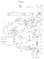
- the automatic labeling machine for goods packed in mesh bags or the like comprises a second roller 101 and an associated counter roller 102, both having an anti-slip surface, which is obtained, for example, by a covering of rubber or the like.
- These rollers 101 and 102 are arranged transversely with respect to the guiding channel 3 of the label tape T, the latter being pulled by the roller 101 and the counter roller 102, conjointly with the roller 6.
- the labeling machine has a support S for its attachment to the packaging machine to which it is applied, normally a bag forming machine (Figs. 1 to 4).
- the support 103 of the counter roller 102 has an elastic sheet 104 at the free end of which the counter roller 102 is supported.
- the support 103 is pivotally mounted through a shaft 105 and has on its other free end a knob 106 to manually pivoting said support 103 counterclockwise in Figs. 1 and 3 to separate the counter roller 102 from the label tape T and the roller 101.
- the operative position of the counter roller 102, applied against the roller 101 with intercalation of the label tape T, is locked by a pin mounted at the knob 106 and urged outward by a spring to enter in an orifice 107 provided in a flange 108.
- the flange 108 is pivotally mounted to the frame 2 on a shaft 105 and may be fixed into position at the frame 2 by a bolt or the like countersunk into an orifice 109 of said flange 108. To be able to adjust said operating position there is an oblong orifice 110 in the frame 2.
- the printer head 10 of high definition is mounted, in the same way as the counter roller 102, at a support 111 fixed at an elastic sheet 112, said support 111 having a pivot shaft 113, a knob 114 with an associated locking pin and spring for its locking into an orifice 115 of a pivotal flange 116 with an orifice 117 for the fixing of its position at the frame and the adjustment of the operating position of the printer head 10.
- An oblong orifice 118 is formed in the frame 2 to permit said adjustment.
- the sheet 112 is fixed to a short bar 119 suitably adjusted in an orifice of the support 111 which permits swivel motion of said head 10 around the axis of said bar 119 for a better adaptation of the head 10 against the upper surface of the labels intercalated between the head 10 and the roller 6.
- the user displaces the knobs 106 and 114 against the elastic action of their respective springs (not shown), whereby the pins mounted in said knobs are raised and separated them from their associated orifices 107 and 115, respectively, so that a turning movement in the counterclockwise direction of the support 103 and clockwise of the support 111 according to Figs. 1 and 3 is possible, so that the counter roller 102 and the head 10 are separated from the label tape to the desired extent, to make these zones of the machine accessible to perform operations of maintenance, tests, adjustments, and other operations thereon.
- the moving blade 16 of the cutter for separating the leading label from the tape is actuated by independent first drive means, formed in this example by a double-acting pneumatic cylinder 120 (Figs. 2 to 4) whose piston rod is articulated to the moving blade 16.
- the displacement of the carriage 18 is carried out by independent second drive means which in this example are formed by a double-acting pneumatic cylinder 121 (Figs. 1, 2, 3, and 4) which is linked to a support 122 which is in turn mounted to the carriage 18.
- independent second drive means which in this example are formed by a double-acting pneumatic cylinder 121 (Figs. 1, 2, 3, and 4) which is linked to a support 122 which is in turn mounted to the carriage 18.
- the pivotal movement of the finger 27 with the claws 28 is produced by independent third drive means which in this example are formed by a double-acting pneumatic cylinder 123 (Figs. 2 and 4) whose piston rod is articulated to the link 23 which is in turn rigidly fixed to the link 24 (Figs. 1 to 3) by the brace 26 (Figs. 1, 3, and 4) to which the finger 27 is fixed.
- the pair of links 23 and 24 are pivotally mounted to the carriage 18 by the transverse shaft 22 which extends through the carriage 18. It is possible to substitute said shaft 22 by two studs fixed to both sides of the carriage 18 and aligned with one another.
- the independent first to third drive means 120, 121 and 123 may be of any other conventional form to obtain the alternating or back and forth displacement of the moving knife 16, of the displacement of the carriage 18, and the pivoting of the finger 27.
- the gear motor 7 has a pulley 124 which is linked to another pulley 125 joined to the roller 101 through a chain 126 (Figs. 2 and 4 and shown in dotted lines in Fig. 1).
- the roller 101 is fixedly connected to a toothed gear 127 which meshes with another toothed gear 128 fixedly connected to the roller 6 so that the turning of the pulley 124 of the gear motor 7 causes the turning of the roller 101 in the direction of advance of the label tape T and the turning of the toothed gear 127 causes the turning in the opposite direction of the toothed gear 128 and as a result of that, the turning of the roller 6 in the direction of advance of the label tape T downwardly.
- Fig. 4 are represented the arrows indicating the described turning directions.
- the gear motor 7 is mounted on the frame 2 by attachment means, such as bolts with nuts which traverse oblong orifices 129 (in Fig. 4 three such orifices are shown) and the shaft of the gear motor 7 traverses another oblong orifice 130 to permit said adjustment.
- attachment means such as bolts with nuts which traverse oblong orifices 129 (in Fig. 4 three such orifices are shown) and the shaft of the gear motor 7 traverses another oblong orifice 130 to permit said adjustment.
- the roller 6 has joined to it a knob 131 (Fig. 2) for its manual rotation. Manual turning of said roller 6, thereby turning the roller 101 through the pair of toothed gears 128 and 127 is done to perform tests and adjustments on the labeling machine.
- the transmission means between the gear motor 7 and the roller 101 may be comprised of conventional components other than the chain 126 described above.
- the electric motor which is a part of the gear motor 7 may have a brake, for example electronic by inversion or other conventional one, for the cyclic stopping of same during the operations of the labeling machine.
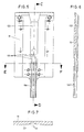
- the supporting plate 19 of the labels has a central longitudinal channel 132 (Figs. 5 to 7) and a stepped interior 133 which extend in the prolongation 19a as represented in said Figs. 5 to 7.
- This channel and steps favor the engagement of the label by the claws 28 of the finger 27 at time a certain curve is produced in the label, facilitating the correct delivery of same to the packaging machine and favor the application of the means for affixing the label to a bag or the like.
- the control and the coordination of the different movements of the labeling machine can be carried out by a computer, connected to the various organs and means of the machine and to control means for the user.
- the operation of the labeling machine in question is, along general lines, the following: Starting with the phase in which the label tape is already installed and arrives at the printer head 10 and is supported on the roller 6, the printer head 10 having already carried out the printing upon the label, the gear motor 7 turns the rollers 101 and 6 in the direction indicated by the arrows in Fig. 4 until the leading label of the label series which is to be printed is engaged by the finger 27 which has pivoted from the formerly raised position I of Fig. 1 to the lowered position II indicated in broken lines in Fig. 1, by the operation of the pneumatic cylinder 123, at which time the pneumatic cylinder 120 is operated which displaces the moving blade 16 of the cutter to perform the cutting which separates the label from the label tape.
- the pneumatic cylinder 121 is operated which moves the carriage 18 down and thereby advances the label engaged the finger 27 with its claws 28 applied against the label, or its appendix if there is one, by introducing its center part into the channel 132 and in the steps 133 of the supporting plate 19 and of its prolongation 19a (position III of maximum descent of the finger 27 represented in Figs. 3 and 4) to present said label to the packaging machine for the attachment of said label, for example by a staple, to a bag or the like conformed and filled with the desired product in said packaging machine.
- the cited pneumatic cylinders will return the moving blade 16 to its open or idle position, the finger 27 to its open or separated position I removed from the support plate 19 and the carriage 18 to its upper position shown in Fig. 1 at an appropriate timing. The cycle is repeated for each label.
Landscapes
- Labeling Devices (AREA)
Claims (3)
- Automatisches Etikettiergerät für Behälter in Form von Netzsäcken oder dergleichen, enthaltend einen Wickel aus einem zusammenhängenden Band aus Etiketten, die nacheinander einer Maschine zum Befüllen der Behälter mit Produkten zuzuführen sind, weiterhin enthaltend:gekennzeichneteine Führungseinrichtung (3), die an einem Rahmen (2) befestigt ist, zum Führen des Bandes (2), einen Schneider (16) zum Abtrennen von Etiketten von dem Band (T), eine Steuereinrichtung und eine angetriebene erste Antischlupfrolle (6) zum Fortbewegen des Bandes (T), die quer zu der Führungseinrichtung (3) angeordnet ist und durch die das Band (T) unterstützt wird, um zum Ausläß der Etikettiermaschine gezogen zu werden, einen Druckkopf (10) zum Etikettendrucken, wenn dieser an der Oberfläche des Bandes (T) in einer Zone angebracht ist, in der die entgegengesetzte Oberfläche des Etikettenbandes (T) von der ersten Rolle (6) abgestützt ist, wobei der Druckkopf (10) schwenkbar an einem Halter (111) angebracht ist, der mit einer Handbetätigungseinrichtung (114) versehen ist, um den Druckkopf (10) von dem Etikettenband (T) abzuheben,einen Schlitten (18), der stromabwärts der ersten Rolle (6) angeordnet und der durch Betätigungseinrichtungen nach unten und zurück längs einer Tragplatte (19) verstellbar ist, die eine Führungseinrichtung aufweist, um das Etikettenband (T) während der Verstellung zu führen, und einen zentralen, sich nach unten erstreckenden Kanal (132), der ein gestaltetes Querprofil hat und eine Verlängerung (19a) der Tragplatte (19) aufweist, die ebenfalls mit dem gestalteten Profil versehen ist;ein Paar Lenker (23, 24), die gelenkig in einer gemeinsamen Achse mit der Außenseite den Schlittens (18) verbunden sind, wobei die freien Enden der Lenker (23, 24) durch einen Bügel (26) miteinander verbunden sind, an dem ein Finger befestigt ist, der Klauen (28) zum Anlegen an ein von dem Band (T) abgeschnittenes Etikett aufweist, die dieses innerhalb der Verlängerung (19a) der Tragplatte (19) bei der Abwärtsbewegung des Schlittens (18) vorschieben,durch eine zweite Rolle (101) und eine zugehörige Gegenrolle (102), die an einem Halter (103) montiert ist, der mit einer Handbetätigungseinrichtung (106) versehen ist, wobei beide Rollen (101, 102) eine Antischlupfoberfläche aufweisen und bezüglich der Förderrichtung eines Etikettenbandes (T) stromaufwärts von der ersten Rolle (6), die dem Druckkopf (10) gegenübersteht, parallel zu der ersten Rolle (6) angeordnet sind, wobei durch die zweite Rolle (101) und ihre Gegenrolle (102) zusammen mit der Wirkung der ersten Rolle (6) das Etikettenband (T) gezogen wird;durch unabhängige Antriebseinrichtungen (120, 121, 123) für den Schneider (16), für die Verstellung des Schlitten (18) und für das Schwenken des Fingers (27);dadurch, daß sowohl der Druckkopf (10) als auch die Gegenrolle (102) auf ihren jeweiligen Haltern (111, 103) über elastische Bleche (112, 104) gehalten sind und die Halter (111, 103) unabhängig betätigbar sind, um den Druckkopf (10) und die Gegenrolle (102) von dem Etikettenband (T) abzuheben; unddadurch, daß die ersten und zweiten Rollen (6, 101) für gemeinsame Drehung in zueinander entgegengesetzten Richtungen mechanisch miteinander gekoppelt (127, 128) sind, wobei die eine der Rollen durch eine Motoreinrichtung (7) über zugehörige Antriebsübertragungseinrichtungen (124-126) angetrieben ist.
- Gerät nach Anspruch 1, weiterhin enthaltend Verriegelungseinrichtungen (109, 115) zum Festhalten des Kopfes (10) und der Gegenrolle (102) in ihren Betriebsstellungen.
- Gerät nach Anspruch 2, weiterhin enthaltend Einstelleinrichtungen (110, 118) zur Ermöglichung einer Einstellung der Betriebsstellungen des Kopfes (10) und der Gegenrolle (102).
Applications Claiming Priority (2)
| Application Number | Priority Date | Filing Date | Title |
|---|---|---|---|
| ES9701375 | 1997-06-23 | ||
| ES009701375A ES2148036B1 (es) | 1991-11-11 | 1997-06-23 | Mejoras en el objeto de la patente principal n- 9102494 por maquina etiquetadora automatica para envasadoras en bolsas de malla o similar. |
Publications (2)
| Publication Number | Publication Date |
|---|---|
| EP0887274A1 EP0887274A1 (de) | 1998-12-30 |
| EP0887274B1 true EP0887274B1 (de) | 2001-10-24 |
Family
ID=8299786
Family Applications (1)
| Application Number | Title | Priority Date | Filing Date |
|---|---|---|---|
| EP98500147A Expired - Lifetime EP0887274B1 (de) | 1997-06-23 | 1998-06-22 | Automatisches Etikettiergerät für Netzsäcke oder ähnliche Behälter |
Country Status (5)
| Country | Link |
|---|---|
| US (1) | US6164359A (de) |
| EP (1) | EP0887274B1 (de) |
| JP (1) | JPH1170928A (de) |
| CA (1) | CA2241217A1 (de) |
| DE (1) | DE69802143D1 (de) |
Families Citing this family (2)
| Publication number | Priority date | Publication date | Assignee | Title |
|---|---|---|---|---|
| CN103359307B (zh) * | 2013-05-30 | 2015-01-28 | 宁波成路纸品制造有限公司 | 一种方便卡片穿绳的工装 |
| CN106628471B (zh) * | 2016-12-27 | 2018-12-04 | 绍兴上虞华谊针纺有限公司 | 一种自动送料式切割贴标机构 |
Family Cites Families (9)
| Publication number | Priority date | Publication date | Assignee | Title |
|---|---|---|---|---|
| DE273060C (de) * | ||||
| US4347094A (en) * | 1979-04-05 | 1982-08-31 | Sawara Mfg. Works Co., Ltd. | Label applying apparatus |
| JPS59163134A (ja) * | 1983-02-24 | 1984-09-14 | 渋谷工業 株式会社 | ロ−ルラベルの間欠送り装置 |
| US4954203A (en) * | 1987-12-07 | 1990-09-04 | Kanzaki Seishi Co., Ltd. | Labelling system |
| US5300181A (en) * | 1991-10-09 | 1994-04-05 | Osaka Sealing Printing Co., Ltd. | Label sticking apparatus |
| ES2049144B1 (es) * | 1991-11-11 | 1996-07-16 | Daumar Talleres | Maquina etiquetadora automatica, para envasadoras en bolsas de malla o similar. |
| US5413651A (en) * | 1993-03-23 | 1995-05-09 | B&H Manufacturing Company | Universal roll-fed label cutter |
| US5895552A (en) * | 1994-09-14 | 1999-04-20 | Osaka Sealing Printing Co., Ltd. | Bonding apparatus for cutting label continuum having labels formed successively and bonding label to object |
| DE69609380T2 (de) * | 1995-06-09 | 2001-02-15 | Tamarack Products, Inc. | Verfahren zum Handhaben dünner Bänder und Folien |
-
1998
- 1998-06-22 EP EP98500147A patent/EP0887274B1/de not_active Expired - Lifetime
- 1998-06-22 US US09/102,288 patent/US6164359A/en not_active Expired - Fee Related
- 1998-06-22 DE DE69802143T patent/DE69802143D1/de not_active Expired - Lifetime
- 1998-06-22 CA CA002241217A patent/CA2241217A1/en not_active Abandoned
- 1998-06-23 JP JP10190983A patent/JPH1170928A/ja active Pending
Also Published As
| Publication number | Publication date |
|---|---|
| US6164359A (en) | 2000-12-26 |
| EP0887274A1 (de) | 1998-12-30 |
| DE69802143D1 (de) | 2001-11-29 |
| JPH1170928A (ja) | 1999-03-16 |
| CA2241217A1 (en) | 1998-12-23 |
Similar Documents
| Publication | Publication Date | Title |
|---|---|---|
| US2815620A (en) | Manufacture of packages with detachable registered printed appendages | |
| US6272815B1 (en) | Servo-controlled pouch making apparatus | |
| US6050061A (en) | Pouch carrying apparatus | |
| US4073122A (en) | Printing apparatus | |
| US6247292B1 (en) | Package wrapping method and machine | |
| US3908340A (en) | Apparatus for feeding and applying individual lids to containers | |
| US5468080A (en) | Poly bag printer for packaging machine | |
| EP0405595B1 (de) | Vorrichtung für die kontinuierliche Herstellung von Netzbeuteln | |
| JP2777145B2 (ja) | 包装機械 | |
| JPS59134116A (ja) | 鎖状に連続して接続されたプラスチツク袋用の包装装置 | |
| DE1511873C3 (de) | Vorrichtung zur Abgabe von Etiketten | |
| US20200087013A1 (en) | Wrapping machine printer arrangement and wrapping machine film cutter arrangement | |
| CA1207573A (en) | Plastic bag handle aperture forming apparatus | |
| EP0887274B1 (de) | Automatisches Etikettiergerät für Netzsäcke oder ähnliche Behälter | |
| GB1596585A (en) | Wrapping apparatus | |
| US7032898B2 (en) | Wire-stitching apparatus for producing wire stitched print items | |
| EP0542663B1 (de) | Automatisches Etikettiergerät für Netzsäcke oder ähnliche Behälter | |
| EP0025711B1 (de) | Apparat zum Herstellen von Beuteln | |
| JPS58112905A (ja) | 袋形式パツケ−ジを製造するための方法及び装置 | |
| US3650873A (en) | Bag making machine having heat sealer whose dwell time is adjustable | |
| US4180962A (en) | Wrapping apparatus | |
| US2694964A (en) | Apparatus for nicking the edge of the web passing through a wrapping machine | |
| US4228884A (en) | Wrapping apparatus | |
| NL8204097A (nl) | Werkwijze en middelen voor het aan draagbanden rijgen van gespen. | |
| EP0208766A4 (de) | Verpackungsanordnung und verfahren. |
Legal Events
| Date | Code | Title | Description |
|---|---|---|---|
| PUAI | Public reference made under article 153(3) epc to a published international application that has entered the european phase |
Free format text: ORIGINAL CODE: 0009012 |
|
| AK | Designated contracting states |
Kind code of ref document: A1 Designated state(s): BE DE DK FR GB GR IE IT NL PT |
|
| AX | Request for extension of the european patent |
Free format text: AL;LT;LV;MK;RO;SI |
|
| 17P | Request for examination filed |
Effective date: 19990506 |
|
| AKX | Designation fees paid |
Free format text: BE DE DK FR GB GR IE IT NL PT |
|
| 17Q | First examination report despatched |
Effective date: 20000828 |
|
| GRAG | Despatch of communication of intention to grant |
Free format text: ORIGINAL CODE: EPIDOS AGRA |
|
| GRAG | Despatch of communication of intention to grant |
Free format text: ORIGINAL CODE: EPIDOS AGRA |
|
| GRAG | Despatch of communication of intention to grant |
Free format text: ORIGINAL CODE: EPIDOS AGRA |
|
| GRAH | Despatch of communication of intention to grant a patent |
Free format text: ORIGINAL CODE: EPIDOS IGRA |
|
| GRAA | (expected) grant |
Free format text: ORIGINAL CODE: 0009210 |
|
| AK | Designated contracting states |
Kind code of ref document: B1 Designated state(s): BE DE DK FR GB GR IE IT NL PT |
|
| PG25 | Lapsed in a contracting state [announced via postgrant information from national office to epo] |
Ref country code: NL Free format text: LAPSE BECAUSE OF FAILURE TO SUBMIT A TRANSLATION OF THE DESCRIPTION OR TO PAY THE FEE WITHIN THE PRESCRIBED TIME-LIMIT Effective date: 20011024 Ref country code: IT Free format text: LAPSE BECAUSE OF FAILURE TO SUBMIT A TRANSLATION OF THE DESCRIPTION OR TO PAY THE FEE WITHIN THE PRE;WARNING: LAPSES OF ITALIAN PATENTS WITH EFFECTIVE DATE BEFORE 2007 MAY HAVE OCCURRED AT ANY TIME BEFORE 2007. THE CORRECT EFFECTIVE DATE MAY BE DIFFERENT FROM THE ONE RECORDED.SCRIBED TIME-LIMIT Effective date: 20011024 Ref country code: BE Free format text: LAPSE BECAUSE OF FAILURE TO SUBMIT A TRANSLATION OF THE DESCRIPTION OR TO PAY THE FEE WITHIN THE PRESCRIBED TIME-LIMIT Effective date: 20011024 |
|
| REG | Reference to a national code |
Ref country code: IE Ref legal event code: FG4D |
|
| REF | Corresponds to: |
Ref document number: 69802143 Country of ref document: DE Date of ref document: 20011129 |
|
| REG | Reference to a national code |
Ref country code: GB Ref legal event code: IF02 |
|
| PG25 | Lapsed in a contracting state [announced via postgrant information from national office to epo] |
Ref country code: PT Free format text: LAPSE BECAUSE OF FAILURE TO SUBMIT A TRANSLATION OF THE DESCRIPTION OR TO PAY THE FEE WITHIN THE PRESCRIBED TIME-LIMIT Effective date: 20020124 Ref country code: DK Free format text: LAPSE BECAUSE OF FAILURE TO SUBMIT A TRANSLATION OF THE DESCRIPTION OR TO PAY THE FEE WITHIN THE PRESCRIBED TIME-LIMIT Effective date: 20020124 |
|
| PG25 | Lapsed in a contracting state [announced via postgrant information from national office to epo] |
Ref country code: GR Free format text: LAPSE BECAUSE OF FAILURE TO SUBMIT A TRANSLATION OF THE DESCRIPTION OR TO PAY THE FEE WITHIN THE PRESCRIBED TIME-LIMIT Effective date: 20020125 Ref country code: DE Free format text: LAPSE BECAUSE OF FAILURE TO SUBMIT A TRANSLATION OF THE DESCRIPTION OR TO PAY THE FEE WITHIN THE PRESCRIBED TIME-LIMIT Effective date: 20020125 |
|
| ET | Fr: translation filed | ||
| NLV1 | Nl: lapsed or annulled due to failure to fulfill the requirements of art. 29p and 29m of the patents act | ||
| PG25 | Lapsed in a contracting state [announced via postgrant information from national office to epo] |
Ref country code: GB Free format text: LAPSE BECAUSE OF NON-PAYMENT OF DUE FEES Effective date: 20020622 |
|
| PG25 | Lapsed in a contracting state [announced via postgrant information from national office to epo] |
Ref country code: IE Free format text: LAPSE BECAUSE OF NON-PAYMENT OF DUE FEES Effective date: 20020624 |
|
| PGFP | Annual fee paid to national office [announced via postgrant information from national office to epo] |
Ref country code: FR Payment date: 20020625 Year of fee payment: 5 |
|
| PLBE | No opposition filed within time limit |
Free format text: ORIGINAL CODE: 0009261 |
|
| STAA | Information on the status of an ep patent application or granted ep patent |
Free format text: STATUS: NO OPPOSITION FILED WITHIN TIME LIMIT |
|
| 26N | No opposition filed | ||
| GBPC | Gb: european patent ceased through non-payment of renewal fee |
Effective date: 20020622 |
|
| REG | Reference to a national code |
Ref country code: IE Ref legal event code: MM4A |
|
| PG25 | Lapsed in a contracting state [announced via postgrant information from national office to epo] |
Ref country code: FR Free format text: LAPSE BECAUSE OF NON-PAYMENT OF DUE FEES Effective date: 20040227 |
|
| REG | Reference to a national code |
Ref country code: FR Ref legal event code: ST |