EP0886110A2 - Method for preparing sanitary water in a mixed system - Google Patents
Method for preparing sanitary water in a mixed system Download PDFInfo
- Publication number
- EP0886110A2 EP0886110A2 EP98106389A EP98106389A EP0886110A2 EP 0886110 A2 EP0886110 A2 EP 0886110A2 EP 98106389 A EP98106389 A EP 98106389A EP 98106389 A EP98106389 A EP 98106389A EP 0886110 A2 EP0886110 A2 EP 0886110A2
- Authority
- EP
- European Patent Office
- Prior art keywords
- heating
- water
- temperature
- circulation pump
- domestic
- Prior art date
- Legal status (The legal status is an assumption and is not a legal conclusion. Google has not performed a legal analysis and makes no representation as to the accuracy of the status listed.)
- Granted
Links
- XLYOFNOQVPJJNP-UHFFFAOYSA-N water Substances O XLYOFNOQVPJJNP-UHFFFAOYSA-N 0.000 title claims abstract description 52
- 238000000034 method Methods 0.000 title claims description 19
- 238000010438 heat treatment Methods 0.000 claims abstract description 44
- 239000008236 heating water Substances 0.000 claims abstract description 33
- 230000001105 regulatory effect Effects 0.000 claims abstract 4
- 238000002360 preparation method Methods 0.000 claims description 5
- 238000010079 rubber tapping Methods 0.000 description 2
- 238000009835 boiling Methods 0.000 description 1
- 239000000567 combustion gas Substances 0.000 description 1
- 238000001514 detection method Methods 0.000 description 1
- 238000010586 diagram Methods 0.000 description 1
- 238000005265 energy consumption Methods 0.000 description 1
- 239000007789 gas Substances 0.000 description 1
- 238000004904 shortening Methods 0.000 description 1
Images

Classifications
-
- F—MECHANICAL ENGINEERING; LIGHTING; HEATING; WEAPONS; BLASTING
- F24—HEATING; RANGES; VENTILATING
- F24H—FLUID HEATERS, e.g. WATER OR AIR HEATERS, HAVING HEAT-GENERATING MEANS, e.g. HEAT PUMPS, IN GENERAL
- F24H15/00—Control of fluid heaters
- F24H15/20—Control of fluid heaters characterised by control inputs
- F24H15/212—Temperature of the water
- F24H15/219—Temperature of the water after heating
-
- F—MECHANICAL ENGINEERING; LIGHTING; HEATING; WEAPONS; BLASTING
- F24—HEATING; RANGES; VENTILATING
- F24D—DOMESTIC- OR SPACE-HEATING SYSTEMS, e.g. CENTRAL HEATING SYSTEMS; DOMESTIC HOT-WATER SUPPLY SYSTEMS; ELEMENTS OR COMPONENTS THEREFOR
- F24D19/00—Details
- F24D19/10—Arrangement or mounting of control or safety devices
- F24D19/1006—Arrangement or mounting of control or safety devices for water heating systems
- F24D19/1066—Arrangement or mounting of control or safety devices for water heating systems for the combination of central heating and domestic hot water
- F24D19/1069—Arrangement or mounting of control or safety devices for water heating systems for the combination of central heating and domestic hot water regulation in function of the temperature of the domestic hot water
-
- F—MECHANICAL ENGINEERING; LIGHTING; HEATING; WEAPONS; BLASTING
- F24—HEATING; RANGES; VENTILATING
- F24H—FLUID HEATERS, e.g. WATER OR AIR HEATERS, HAVING HEAT-GENERATING MEANS, e.g. HEAT PUMPS, IN GENERAL
- F24H15/00—Control of fluid heaters
- F24H15/10—Control of fluid heaters characterised by the purpose of the control
- F24H15/156—Reducing the quantity of energy consumed; Increasing efficiency
-
- F—MECHANICAL ENGINEERING; LIGHTING; HEATING; WEAPONS; BLASTING
- F24—HEATING; RANGES; VENTILATING
- F24H—FLUID HEATERS, e.g. WATER OR AIR HEATERS, HAVING HEAT-GENERATING MEANS, e.g. HEAT PUMPS, IN GENERAL
- F24H15/00—Control of fluid heaters
- F24H15/10—Control of fluid heaters characterised by the purpose of the control
- F24H15/174—Supplying heated water with desired temperature or desired range of temperature
-
- F—MECHANICAL ENGINEERING; LIGHTING; HEATING; WEAPONS; BLASTING
- F24—HEATING; RANGES; VENTILATING
- F24H—FLUID HEATERS, e.g. WATER OR AIR HEATERS, HAVING HEAT-GENERATING MEANS, e.g. HEAT PUMPS, IN GENERAL
- F24H15/00—Control of fluid heaters
- F24H15/20—Control of fluid heaters characterised by control inputs
- F24H15/238—Flow rate
-
- F—MECHANICAL ENGINEERING; LIGHTING; HEATING; WEAPONS; BLASTING
- F24—HEATING; RANGES; VENTILATING
- F24H—FLUID HEATERS, e.g. WATER OR AIR HEATERS, HAVING HEAT-GENERATING MEANS, e.g. HEAT PUMPS, IN GENERAL
- F24H15/00—Control of fluid heaters
- F24H15/30—Control of fluid heaters characterised by control outputs; characterised by the components to be controlled
- F24H15/335—Control of pumps, e.g. on-off control
- F24H15/34—Control of the speed of pumps
-
- F—MECHANICAL ENGINEERING; LIGHTING; HEATING; WEAPONS; BLASTING
- F24—HEATING; RANGES; VENTILATING
- F24H—FLUID HEATERS, e.g. WATER OR AIR HEATERS, HAVING HEAT-GENERATING MEANS, e.g. HEAT PUMPS, IN GENERAL
- F24H15/00—Control of fluid heaters
- F24H15/30—Control of fluid heaters characterised by control outputs; characterised by the components to be controlled
- F24H15/355—Control of heat-generating means in heaters
- F24H15/36—Control of heat-generating means in heaters of burners
-
- Y—GENERAL TAGGING OF NEW TECHNOLOGICAL DEVELOPMENTS; GENERAL TAGGING OF CROSS-SECTIONAL TECHNOLOGIES SPANNING OVER SEVERAL SECTIONS OF THE IPC; TECHNICAL SUBJECTS COVERED BY FORMER USPC CROSS-REFERENCE ART COLLECTIONS [XRACs] AND DIGESTS
- Y02—TECHNOLOGIES OR APPLICATIONS FOR MITIGATION OR ADAPTATION AGAINST CLIMATE CHANGE
- Y02B—CLIMATE CHANGE MITIGATION TECHNOLOGIES RELATED TO BUILDINGS, e.g. HOUSING, HOUSE APPLIANCES OR RELATED END-USER APPLICATIONS
- Y02B30/00—Energy efficient heating, ventilation or air conditioning [HVAC]
- Y02B30/70—Efficient control or regulation technologies, e.g. for control of refrigerant flow, motor or heating
Definitions
- the invention is based on a method for Domestic hot water provision in a combined system the genus of the main claim.
- To increase the Domestic hot water convenience of such combination heaters is over known from DE 42 37 136 A1, to shorten the heating-up time of the hot water, the circulating quantity of the heating water or the Flow rate of the domestic water depending on the To regulate the temperature of the heating water.
- the regulation takes place through a thermally controlled valve that either arranged in the heating circuit or as a bypass to DHW heat exchanger is switched.
- the control method according to the invention has the advantage that a shortening of the heating time of the domestic water without additional complex in the hydraulic heating circuit components can be integrated.
- the invention Control procedures only require the use of one speed-adjustable circulation pump, which also for Reduction of secondary energy consumption by heaters and to reduce operating noise in the heating circuit contributes.
- the process water is heated up in a continuous flow principle in a simple manner in that at a certain The temperature of the heating water switched on the circulation pump and the speed of the circulation pump and thus the Circulation quantity of the heating water depending on it Temperature increased to a predeterminable temperature value becomes. Is the preselected temperature of the heating water and the desired outlet temperature of the domestic water the circulation pump is reached during the further Hot water supply at constant speed continued to operate.
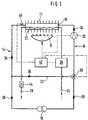
- a device for Heating of circulating heating water and process water has a arranged in a heating circuit and from Heating water flowing through the heating heat exchanger 10, whose fins 11 from the combustion gases of a burner 12 are immediately applied.
- the heating heat exchanger 10 supplies one between a lead section 14 and a return section 16 of the heating circuit arranged heating device, for example a radiator 18, with heating water, a 16 in the return section speed-adjustable circulation pump 20 for conveying the rotating Heating water is arranged.
- a 16 in the return section speed-adjustable circulation pump 20 for conveying the rotating Heating water is arranged.
- For the Domestic hot water preparation is in the heating heat exchanger 10 arranged and surrounded by the heating water Domestic water heat exchanger 22 is provided.
- One with the Process water heat exchanger 22 connected Process water supply device feeds one or more Dispensing points via a cold water connection 24, a Flow of the hot water sensor 26 and a Hot water connection 28 with hot water.
- Heating water to the in the domestic water heat exchanger 22 flowing hot water can take place is via an in Return section 16 of the heating circuit 14, 16 arranged three-way valve 30 and via a bypass 32 the heating circuit 14, 16 separated.
- the heating heat exchanger 10 on the Flow section 14, bypass 32, three-way valve 30, Return section 16 and circulation pump 20 back to Heater heat exchanger 10 leads, is the following inner Heating circuit called 36, while the heating circuit, the from the heating heat exchanger 10 via flow section 14, Radiator 18 and return section 16 back to Heater heat exchanger 10 leads, in the following as the outer Heating circuit 38 is called.
- a temperature sensor 40 for Detection of the flow temperature of the heating water arranged.
- the burner 12, the circulation pump 20, the sensor 26, the three-way valve 30 and the temperature sensor 40 are over Lines (shown in dashed lines) with a central Control unit 42 connected.
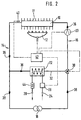
- FIG 2 is a second embodiment of a device for heating circulating heating water and process water shown.
- the hot water heat exchanger 22 is not in the Heating heat exchanger 10, but e.g. as Plate heat exchanger separately in the bypass line 32 arranged.
- the device for heating circulating heating water and process water works in the following way:
- the burner 12 is ignited and with With the help of the circulation pump 20, the outer heating circuit 38 activated, the in the outer heating circuit 38th arranged radiator 18 can be charged with heating water.
- the speed of the circulation pump 20 is increased until the in Control unit 42 preset target temperature for the Heating water, which later the maximum outlet temperature of the domestic water is reached.
- the Flow temperature sensor 40 becomes the actual value Heating water temperature recorded and the heating water up to set heating water temperature of e.g. 60 ° C heated.
- FIG. 3 shows experimentally determined temperature profiles of the domestic water from combination heaters with one Heating power of 24 kW and a hot water flow rate of 61 / min.
- Line a represents the temperature curve hot water heating according to a known method with constant speed of the circulation pump 20, at a Execution of the heating device according to Figure 1.
- line b shows the temperature profile of the control method according to the invention according to the first Embodiment according to Figure 1. This comparison makes clearly that the temperature rise time of the domestic water significantly shortened at the beginning of domestic hot water preparation on the one hand, which improves the convenience of hot water is and on the other hand by shorter tapping operations of gas and Water consumption is reduced.
- Line d represents the time course of the speed increase of the circulation pump 20.
- the circulation pump 20 according to the control method according to the first embodiment (line b) after about 12s switched on when the domestic water is at a temperature of approx. Has reached 35 ° C.
- the increase the speed of the circulation pump 20 increased to boiling noises in To avoid hot water heat exchanger 22. Has the Heating water and therefore the hot water preset target temperature is reached, the Circulation pump 20 at constant speed during the Continuing to use domestic water.
Abstract
Description
Die Erfindung geht aus von einem Verfahren zur
Brauchwasserbereitstellung in einem kombinierten System nach
der Gattung des Hauptanspruchs. Zur Erhöhung des
Brauchwasserkomforts derartiger Kombi- Heizgeräte ist es aus
der DE 42 37 136 A1 bekannt, zur Verkürzung der Aufheizzeit
des Brauchwassers die Umlaufmenge des Heizwassers oder die
Durchflußmenge des Brauchwassers in Abhängigkeit von der
Temperatur des Heizwassers zu regeln. Die Regelung erfolgt
dabei durch ein thermisch gesteuertes Ventil, das entweder
im Heizkreislauf angeordnet oder als Bypass zum
Brauchwasserwärmetauscher geschaltet ist.The invention is based on a method for
Domestic hot water provision in a combined system
the genus of the main claim. To increase the
Domestic hot water convenience of such combination heaters is over
known from
Das erfindungsgemäße Regelverfahren hat den Vorteil, daß eine Verkürzung der Aufheizzeit des Brauchwassers ohne zusätzliche aufwendig in den hydraulischen Heizkreislauf einzubindende Bauteile erfolgen kann. Das erfindungsgemäße Regelverfahren erfordert lediglich den Einsatz einer drehzahlregelbaren Umlaufpumpe, die darüberhinaus auch zur Senkung des Sekundär- Energieverbrauchs von Heizgeräten und zur Reduzierung der Betriebsgeräusche im Heizkreislauf beiträgt.The control method according to the invention has the advantage that a shortening of the heating time of the domestic water without additional complex in the hydraulic heating circuit components can be integrated. The invention Control procedures only require the use of one speed-adjustable circulation pump, which also for Reduction of secondary energy consumption by heaters and to reduce operating noise in the heating circuit contributes.
Das Aufheizen des Brauchwassers im Durchlaufprinzip erfolgt auf einfache Art und Weise dadurch, daß bei einer bestimmten Temperatur des Heizungswassers die Umwälzpumpe eingeschaltet wird und die Drehzahl der Umwälzpumpe und damit die Umlaufmenge des Heizungswassers in Abhängigkeit von dessen Temperatur bis auf einen vorgebbaren Temperaturwert erhöht wird. Ist die vorgewählte Temperatur des Heizungswassers und damit die gewünschte Auslauftemperatur des Brauchwassers erreicht, wird die Umlaufpumpe während der weiteren Brauchwasserbereitstellung mit konstanter Drehzahl weiterbetrieben.The process water is heated up in a continuous flow principle in a simple manner in that at a certain The temperature of the heating water switched on the circulation pump and the speed of the circulation pump and thus the Circulation quantity of the heating water depending on it Temperature increased to a predeterminable temperature value becomes. Is the preselected temperature of the heating water and the desired outlet temperature of the domestic water the circulation pump is reached during the further Hot water supply at constant speed continued to operate.
In der Zeichnung sind zwei Vorrichtungen zur Durchführung des erfindungsgemäßen Verfahrens dargestellt, die in der nachfolgenden Beschreibung näher erläutert werden. Es zeigen Figur 1 und 2 zwei schematisch dargestellte Einrichtungen zum Erhitzen von Heizungswasser und Brauchwasser und Figur 3 ein Diagramm mit der Darstellung von Temperaturverläufen des Brauchwassers während der Aufheizzeit.In the drawing are two devices for implementation of the inventive method shown in the following description will be explained in more detail. Show it Figures 1 and 2 two schematically shown devices for heating heating water and process water and Figure 3 a diagram showing the temperature profiles of the Domestic hot water during the heating up period.
Das zur Durchführung des erfindungsgemäßen Verfahrens
vorgesehene erste Ausführungsbeispiel einer Einrichtung zum
Erhitzen von umlaufendem Heizungswasser und Brauchwasser
weist einen in einem Heizungskreislauf angeordneten und vom
Heizungswasser durchströmten Heizungswärmetauscher 10 auf,
dessen Lamellen 11 von den Verbrennungsgasen eines Brenners
12 unmittelbar beaufschlagt sind. Der Heizungswärmetauscher
10 versorgt eine zwischen einem Vorlaufabschnitt 14 und
einem Rücklaufabschnitt 16 des Heizungskreislaufs
angeordnete Heizeinrichtung, zum Beispiel einen Heizkörper
18, mit Heizungswasser, wobei im Rücklaufabschnitt 16 eine
drehzahlregelbare Umlaufpumpe 20 zum Fördern des umlaufenden
Heizungswassers angeordnet ist. Für die
Brauchwasserbereitung ist ein im Heizungswärmetauscher 10
angeordneter und vom Heizungswasser umströmter
Brauchwasserwärmetauscher 22 vorgesehen. Eine mit dem
Brauchwasserwärmetauscher 22 verbundene
Brauchwasserversorgungseinrichtung speist eine oder mehrere
Zapfstellen über einen Kaltwasseranschluß 24, einen eine
Strömung des Brauchwassers erfassenden Sensor 26 und einen
Warmwasseranschluß 28 mit Brauchwasser.That for carrying out the method according to the invention
provided first embodiment of a device for
Heating of circulating heating water and process water
has a arranged in a heating circuit and from
Heating water flowing through the
Damit für die Brauchwasserbereitung ein kontinuierlicher
Warmeübergang von im Heizungswärmetauscher 10 befindlichem
Heizungswasser auf das im Brauchwasserwärmetauscher 22
strömende Brauchwasser stattfinden kann, wird über ein im
Rücklaufabschnitt 16 des Heizungskreislaufs 14, 16
angeordnetes Drei-Wege-Ventil 30 und über einen Bypass 32
der Heizungskreislauf 14, 16 aufgetrennt. Der
Heizungskreislauf, der vom Heizungswärmetauscher 10 über den
Vorlaufabschnitt 14, Bypass 32, Drei-Wege-Ventil 30,
Rücklaufabschnitt 16 und Umlaufpumpe 20 zurück zum
Heizungswärmetauscher 10 führt, wird im folgenden innerer
Heizkreislauf 36 genannt, während der Heizungskreislauf, der
vom Heizungswärmetauscher 10 über Vorlaufabschnitt 14,
Heizkörper 18 und Rücklaufabschnitt 16 zurück zum
Heizungswärmetauscher 10 führt, im folgenden als äußerer
Heizkreislauf 38 bezeichnet wird. Weiterhin ist am Ausgang
des Heizungswärmetauschers 10 ein Temperaturfühler 40 zur
Erfassung der Vorlauftemperatur des Heizungswassers
angeordnet. So that for the hot water preparation a continuous
Heat transfer from located in the
Der Brenner 12, die Umlaufpumpe 20, der Sensor 26, das Drei-Wege-Ventil
30 und der Temperaturfühler 40 sind über
Leitungen (gestrichelt dargestellt) mit einem zentralen
Steuergerät 42 verbunden.The
In Figur 2 ist eine zweite Ausführungsform einer Einrichtung
zum Erhitzen von umlaufendem Heizungswasser und Brauchwasser
dargestellt. Im Unterschied zum ersten Ausführungsbeispiel
ist der Brauchwasserwärmetauscher 22 nicht im
Heizungswärmetauscher 10, sondern z.B. als
Plattenwärmetauscher separat in der Bypassleitung 32
angeordnet.In Figure 2 is a second embodiment of a device
for heating circulating heating water and process water
shown. In contrast to the first embodiment
the hot
Die Einrichtung zum Erhitzen von umlaufendem Heizungswasser und Brauchwasser arbeitet auf folgende Art und Weise:The device for heating circulating heating water and process water works in the following way:
Liegt zum Beispiel über eine Raumthermostatregelung eine
Wärmeanforderung an, so wird der Brenner 12 gezündet und mit
Hilfe der Umwälzpumpe 20 der äußere Heizkreislauf 38
aktiviert, wobei die im äußeren Heizkreislauf 38
angeordneten Heizkörper 18 mit Heizwasser beschickt werden.For example, if there is a room thermostat control
Heat request, the
Durch das Öffnen eines am Warmwasseranschluß 28 angeordneten
Ventils 44, zum Beispiel das Warmwasserventil einer
Einhebelmischbatterie wird mit Hilfe des Sensors 26 der
Befehl zur Brauchwassererwärmung gegeben, indem ein
entsprechendes Zapfvorbereitungssignal an das zentrale
Steuergerät 42 abgegeben wird, daraufhin der Brenner 12
gezündet wird und die Umlaufpumpe 20 bei einer durch den
Vorlauftemperaturfühler 40 erfaßten Temperatur des
Heizungswassers von ca. 35 ° eingeschaltet wird. Das Drei-Wege-Ventil
30 wird so geschaltet, daß das Heizungswasser im
inneren Heizkreislauf 36 zu zirkulieren beginnt.By opening one arranged on the
Proportional mit der Temperaturerhöhung des Heizungswassers
wird die Drehzahl der Umwälzpumpe 20 erhöht, bis die im
Steuergerät 42 voreingestellte Solltemperatur für das
Heizungswasser, die später die maximale Auslauftemperatur
des Brauchwassers bestimmt, erreicht ist. Über den
Vorlauftemperaturfühler 40 wird der Istwert der
Heizwassertemperatur erfaßt und das Heizungswasser bis zur
eingestellten Heizungswassertemperatur von z.B. 60° C
erhitzt.Proportional with the temperature increase of the heating water
the speed of the
In Figur 3 sind experimentell ermittelte Temperaturverläufe
des Brauchwassers von Kombi- Heizgeräten mit einer
Heizleistung von 24 kW und einer Brauchwasserdurchflußmenge
von 61/min aufgezeigt. Linie a stellt den Temperaturverlauf
einer Brauchwassererwärmung nach einem bekannten Verfahren
mit konstanter Drehzahl der Umwälzpumpe 20 dar, bei einer
Ausführung der Heizeinrichtung gemäß Figur 1. Im Vergleich
dazu zeigt Linie b den Temperaturverlauf des
erfindungsgemäßen Regelverfahrens gemäß dem ersten
Ausführungsbeispiel nach Figur 1. Dieser Vergleich macht
deutlich, daß die Temperaturanstiegszeit des Brauchwassers
zu Anfang der Brauchwasserbereitung wesentlich verkürzt
wird, wodurch einerseits der Brauchwasserkomfort verbessert
wird und andererseits durch kürzere Zapfvorgänge der Gas- und
Wasserverbrauch verringert wird.FIG. 3 shows experimentally determined temperature profiles
of the domestic water from combination heaters with one
Heating power of 24 kW and a hot water flow rate
of 61 / min. Line a represents the temperature curve
hot water heating according to a known method
with constant speed of the
Eine weitere Verkürzung der Aufheizzeit wird dadurch erreicht, daß das erfindungsgemäße Regelverfahren mit einer Heizeinrichtung gemäß dem zweiten Ausführungsbeispiel (Figur 2) durchgeführt wird. In Figur 3 ist durch die Linie c der entsprechende Temperaturverlauf dargestellt.This will further shorten the heating-up time achieved that the control method according to the invention with a Heating device according to the second embodiment (Figure 2) is carried out. In Figure 3 by the line c corresponding temperature curve shown.
Linie d stellt den zeitlichen Verlauf der Drehzahlerhöhung
der Umlaufpumpe 20 dar. Wie dieser Verlauf erkennen läßt,
wird die Umlaufpumpe 20 gemäß dem Regelverfahren nach dem
ersten Ausführungsbeispiel (Linie b) nach ca. 12s
eingeschaltet, wenn das Brauchwasser eine Temperatur von ca.
35° C erreicht hat. Nachdem das Brauchwasser nach ca. 18s
eine Temperatur von ca. 50° C erreicht hat, wird der Anstieg
der Drehzahl der Umlaufpumpe 20 erhöht, um Siedegeräusche im
Brauchwasserwärmetauscher 22 zu vermeiden. Hat das
Heizungswasser und damit das Brauchwasser die
voreingestellte Solltemperatur erreicht, wird danach die
Umlaufpumpe 20 mit konstanter Drehzahl während der
Brauchwasserzapfung weiterbetrieben.Line d represents the time course of the speed increase
of the
Claims (2)
Applications Claiming Priority (2)
| Application Number | Priority Date | Filing Date | Title |
|---|---|---|---|
| DE19725951 | 1997-06-19 | ||
| DE19725951A DE19725951A1 (en) | 1997-06-19 | 1997-06-19 | Process for hot water supply in a combined system |
Publications (3)
| Publication Number | Publication Date |
|---|---|
| EP0886110A2 true EP0886110A2 (en) | 1998-12-23 |
| EP0886110A3 EP0886110A3 (en) | 2000-07-12 |
| EP0886110B1 EP0886110B1 (en) | 2004-08-11 |
Family
ID=7832964
Family Applications (1)
| Application Number | Title | Priority Date | Filing Date |
|---|---|---|---|
| EP98106389A Expired - Lifetime EP0886110B1 (en) | 1997-06-19 | 1998-04-08 | Method for preparing sanitary water in a mixed system |
Country Status (3)
| Country | Link |
|---|---|
| EP (1) | EP0886110B1 (en) |
| AT (1) | ATE273487T1 (en) |
| DE (2) | DE19725951A1 (en) |
Cited By (6)
| Publication number | Priority date | Publication date | Assignee | Title |
|---|---|---|---|---|
| EP1148302A2 (en) * | 2000-04-19 | 2001-10-24 | Technische Alternative elektronische Steuerungsgerätegesellschaft m.b.H. | Method for regulating the tapping temperature of sanitary water |
| EP1691138A2 (en) * | 2005-02-15 | 2006-08-16 | Robert Bosch Gmbh | Mixed boiler and method for operating the same |
| EP2077423A1 (en) * | 2008-01-02 | 2009-07-08 | Esbe Ab | Regulation of flow temperature of a liquid in a heating circuit |
| EP2372259A3 (en) * | 2010-03-27 | 2014-01-22 | Robert Bosch GmbH | Method for heating water according to the circulation principle and water heating system |
| EP2372260A3 (en) * | 2010-03-27 | 2014-01-22 | Robert Bosch GmbH | Method for heating water according to the circulation principle and water heating system |
| EP3800403A1 (en) * | 2019-10-01 | 2021-04-07 | Bosch Termoteknik Isitma ve Klima Sanayi Ticaret Anonim Sirketi | Heating device and method for operating a heating device |
Citations (1)
| Publication number | Priority date | Publication date | Assignee | Title |
|---|---|---|---|---|
| DE4237136A1 (en) | 1991-10-31 | 1993-05-06 | Joh. Vaillant Gmbh U. Co, 5630 Remscheid, De | Central- and washing-water-heating control system - regulates flow through washing-water heat-exchanger dependent on medium temperature |
Family Cites Families (4)
| Publication number | Priority date | Publication date | Assignee | Title |
|---|---|---|---|---|
| DE3843376A1 (en) * | 1988-12-23 | 1990-07-05 | Buderus Heiztechnik Gmbh | Heating-up control system of a domestic water storage tank |
| DE4035115C2 (en) * | 1990-03-12 | 1993-11-04 | Sandler Energietechnik | ARRANGEMENT FOR HEATING AND PROVIDING HOT OR HOT WATER OF DRINKING WATER QUALITY |
| GB2281379A (en) * | 1993-08-23 | 1995-03-01 | James Melville Buick | Hot water supply system |
| GB2293438A (en) * | 1994-09-20 | 1996-03-27 | Gledhill Water Storage | The control of water heating apparatus to prevent scalding |
-
1997
- 1997-06-19 DE DE19725951A patent/DE19725951A1/en not_active Ceased
-
1998
- 1998-04-08 EP EP98106389A patent/EP0886110B1/en not_active Expired - Lifetime
- 1998-04-08 AT AT98106389T patent/ATE273487T1/en not_active IP Right Cessation
- 1998-04-08 DE DE59811783T patent/DE59811783D1/en not_active Expired - Lifetime
Patent Citations (1)
| Publication number | Priority date | Publication date | Assignee | Title |
|---|---|---|---|---|
| DE4237136A1 (en) | 1991-10-31 | 1993-05-06 | Joh. Vaillant Gmbh U. Co, 5630 Remscheid, De | Central- and washing-water-heating control system - regulates flow through washing-water heat-exchanger dependent on medium temperature |
Cited By (8)
| Publication number | Priority date | Publication date | Assignee | Title |
|---|---|---|---|---|
| EP1148302A2 (en) * | 2000-04-19 | 2001-10-24 | Technische Alternative elektronische Steuerungsgerätegesellschaft m.b.H. | Method for regulating the tapping temperature of sanitary water |
| EP1148302A3 (en) * | 2000-04-19 | 2003-01-02 | Technische Alternative elektronische Steuerungsgerätegesellschaft m.b.H. | Method for regulating the tapping temperature of sanitary water |
| EP1691138A2 (en) * | 2005-02-15 | 2006-08-16 | Robert Bosch Gmbh | Mixed boiler and method for operating the same |
| EP1691138A3 (en) * | 2005-02-15 | 2010-10-27 | Robert Bosch Gmbh | Mixed boiler and method for operating the same |
| EP2077423A1 (en) * | 2008-01-02 | 2009-07-08 | Esbe Ab | Regulation of flow temperature of a liquid in a heating circuit |
| EP2372259A3 (en) * | 2010-03-27 | 2014-01-22 | Robert Bosch GmbH | Method for heating water according to the circulation principle and water heating system |
| EP2372260A3 (en) * | 2010-03-27 | 2014-01-22 | Robert Bosch GmbH | Method for heating water according to the circulation principle and water heating system |
| EP3800403A1 (en) * | 2019-10-01 | 2021-04-07 | Bosch Termoteknik Isitma ve Klima Sanayi Ticaret Anonim Sirketi | Heating device and method for operating a heating device |
Also Published As
| Publication number | Publication date |
|---|---|
| ATE273487T1 (en) | 2004-08-15 |
| DE59811783D1 (en) | 2004-09-16 |
| EP0886110B1 (en) | 2004-08-11 |
| DE19725951A1 (en) | 1999-01-21 |
| EP0886110A3 (en) | 2000-07-12 |
Similar Documents
| Publication | Publication Date | Title |
|---|---|---|
| DE4421137A1 (en) | Water heater | |
| EP0886110B1 (en) | Method for preparing sanitary water in a mixed system | |
| DE4034918A1 (en) | METHOD FOR ALLOWING THE IMMEDIATE TAP OF WARM WATER | |
| DE19530000C2 (en) | Water heating system | |
| DE102005002932B3 (en) | Solar system regulating method for heating system, involves linking modes of operation, switching threshold, and functions for operation with adjustable switching functions for summer and winter operations of controlling units | |
| DE19725952C2 (en) | Process for hot water supply in a combined system | |
| DE19802362C2 (en) | Process and device for reducing the waiting time for drawing off hot domestic water | |
| EP0936415B1 (en) | Hot water supply installation | |
| DE19517250A1 (en) | Gas-fired water heater with electronically controlled circulation pump | |
| DE19503741A1 (en) | Constant hot water supply system | |
| DE102006028040A1 (en) | Heating system for use in building, has mixing unit for mixing hot water from hot water tank with water from cold water inlet pipe, in order to obtain desired output temperature at end of warm water delivery pipe | |
| DE2529858C2 (en) | Method and device for regulating a heat transfer system | |
| DE19701823B4 (en) | Water heating system | |
| DE19636360C2 (en) | Process for hot water supply in a combined system | |
| DE4034917A1 (en) | Circulating water heater with copper heat exchanger - is connected by special pipe layout with pump and three way valves to floor-heating system | |
| DE4438986A1 (en) | Domestic hot water installation | |
| EP0111838A2 (en) | Space heating installation with several regions | |
| DE19915300B4 (en) | Method and device for operating a heater | |
| DE19704987A1 (en) | Water heater for preventing legionnaire's disease | |
| DE19737250C2 (en) | Control device for heating systems | |
| DE2705493C3 (en) | Mixer tap | |
| AT408573B (en) | WATER HEATER | |
| DE4006964C2 (en) | ||
| AT410834B (en) | Circulation water heater, especially for supplying floor heating system, has return sensor connected to controller that detects return temperature and controller operates burner by modulation | |
| EP1691138A2 (en) | Mixed boiler and method for operating the same |
Legal Events
| Date | Code | Title | Description |
|---|---|---|---|
| PUAI | Public reference made under article 153(3) epc to a published international application that has entered the european phase |
Free format text: ORIGINAL CODE: 0009012 |
|
| AK | Designated contracting states |
Kind code of ref document: A2 Designated state(s): AT DE FR GB IT |
|
| AX | Request for extension of the european patent |
Free format text: AL;LT;LV;MK;RO;SI |
|
| PUAL | Search report despatched |
Free format text: ORIGINAL CODE: 0009013 |
|
| AK | Designated contracting states |
Kind code of ref document: A3 Designated state(s): AT BE CH CY DE DK ES FI FR GB GR IE IT LI LU MC NL PT SE |
|
| AX | Request for extension of the european patent |
Free format text: AL;LT;LV;MK;RO;SI |
|
| 17P | Request for examination filed |
Effective date: 20010112 |
|
| AKX | Designation fees paid |
Free format text: AT DE FR GB IT |
|
| 17Q | First examination report despatched |
Effective date: 20020911 |
|
| GRAP | Despatch of communication of intention to grant a patent |
Free format text: ORIGINAL CODE: EPIDOSNIGR1 |
|
| GRAS | Grant fee paid |
Free format text: ORIGINAL CODE: EPIDOSNIGR3 |
|
| GRAA | (expected) grant |
Free format text: ORIGINAL CODE: 0009210 |
|
| AK | Designated contracting states |
Kind code of ref document: B1 Designated state(s): AT DE FR GB IT |
|
| PG25 | Lapsed in a contracting state [announced via postgrant information from national office to epo] |
Ref country code: GB Free format text: LAPSE BECAUSE OF FAILURE TO SUBMIT A TRANSLATION OF THE DESCRIPTION OR TO PAY THE FEE WITHIN THE PRESCRIBED TIME-LIMIT Effective date: 20040811 Ref country code: FR Free format text: LAPSE BECAUSE OF FAILURE TO SUBMIT A TRANSLATION OF THE DESCRIPTION OR TO PAY THE FEE WITHIN THE PRESCRIBED TIME-LIMIT Effective date: 20040811 |
|
| REG | Reference to a national code |
Ref country code: GB Ref legal event code: FG4D Free format text: NOT ENGLISH |
|
| REF | Corresponds to: |
Ref document number: 59811783 Country of ref document: DE Date of ref document: 20040916 Kind code of ref document: P |
|
| GBV | Gb: ep patent (uk) treated as always having been void in accordance with gb section 77(7)/1977 [no translation filed] |
Effective date: 20040811 |
|
| PG25 | Lapsed in a contracting state [announced via postgrant information from national office to epo] |
Ref country code: AT Free format text: LAPSE BECAUSE OF NON-PAYMENT OF DUE FEES Effective date: 20050408 |
|
| PLBE | No opposition filed within time limit |
Free format text: ORIGINAL CODE: 0009261 |
|
| STAA | Information on the status of an ep patent application or granted ep patent |
Free format text: STATUS: NO OPPOSITION FILED WITHIN TIME LIMIT |
|
| 26N | No opposition filed |
Effective date: 20050512 |
|
| EN | Fr: translation not filed | ||
| EN | Fr: translation not filed | ||
| PGFP | Annual fee paid to national office [announced via postgrant information from national office to epo] |
Ref country code: IT Payment date: 20140424 Year of fee payment: 17 Ref country code: DE Payment date: 20140626 Year of fee payment: 17 |
|
| REG | Reference to a national code |
Ref country code: DE Ref legal event code: R119 Ref document number: 59811783 Country of ref document: DE |
|
| PG25 | Lapsed in a contracting state [announced via postgrant information from national office to epo] |
Ref country code: IT Free format text: LAPSE BECAUSE OF NON-PAYMENT OF DUE FEES Effective date: 20150408 Ref country code: DE Free format text: LAPSE BECAUSE OF NON-PAYMENT OF DUE FEES Effective date: 20151103 |