EP0885374B1 - Dreidimensionale farbbildaufnahme - Google Patents
Dreidimensionale farbbildaufnahme Download PDFInfo
- Publication number
- EP0885374B1 EP0885374B1 EP97903190A EP97903190A EP0885374B1 EP 0885374 B1 EP0885374 B1 EP 0885374B1 EP 97903190 A EP97903190 A EP 97903190A EP 97903190 A EP97903190 A EP 97903190A EP 0885374 B1 EP0885374 B1 EP 0885374B1
- Authority
- EP
- European Patent Office
- Prior art keywords
- target surface
- color
- tapped
- profile
- determining
- Prior art date
- Legal status (The legal status is an assumption and is not a legal conclusion. Google has not performed a legal analysis and makes no representation as to the accuracy of the status listed.)
- Expired - Lifetime
Links
Images

Classifications
-
- G—PHYSICS
- G01—MEASURING; TESTING
- G01B—MEASURING LENGTH, THICKNESS OR SIMILAR LINEAR DIMENSIONS; MEASURING ANGLES; MEASURING AREAS; MEASURING IRREGULARITIES OF SURFACES OR CONTOURS
- G01B11/00—Measuring arrangements characterised by the use of optical techniques
- G01B11/24—Measuring arrangements characterised by the use of optical techniques for measuring contours or curvatures
Definitions
- This invention relates to three dimensional (3-D) color imaging of a profile of a target surface.
- Monochromatic 3-D imaging of objects is well known. It has applicability to the accumulation of detailed data on shapes and surface profiles of objects (articles, scenes, and /or persons) to the automatic inspection or assembly of objects, to robotics generally. and to various medical applications.
- Pirlet and Rioux teach triangulation configurations in which the surface is scanned by a beam of light.
- a synchronously scanning receiver images reflected light onto a position sensitive detector, e.g. a CCD (charge coupled device), to generate electrical signals indicative of range deviations of points on the surface from a reference plane.
- CCD charge coupled device
- Beckman et al. also disclose a measuring system employing the triangulation principle. This patent is directed to techniques for improving resolution by varying the cross-section of the measuring beam, and includes a feature of viewing a lighted dot on the target surface at two different angles to discriminate a true reflection from a false one.
- Mundy et al employ the optical parallax triangulation principle in which a color pattern is projected onto the surface, shifts of wavelength bands being detected on separate detector arrays, these shifts corresponding to the profile of the surface.
- the range data can be detected by methods other than the triangulation method, such as by time of flight (radar) measurement.
- radar time of flight
- United States patent number 5, 177, 556 in the name of Rioux issued January 5,1993 discloses a three dimensional color imaging method and apparatus for determining the color and profile of a target surface.
- Rioux's system is a significant advance over the prior art at that time, and though his system appears to perform its intended function, its functionality and performance are limited in some respects. For example, color detection is not possible if only one of red, blue and green light is present in the object being imaged. Furthermore, in some instances, the sensitivity of the system may be inadequate.
- the system disclosed in patent 5,177,556 is adversely affected by noise present or fluctuations at the light source. Thus, a noisy input laser signal will result in output data adversely affected by the noise.
- an optical method for determining the color and profile of a target surface. The method comprises the steps of:
- the invention further provides the method as defined above of determining the color and profile of a target surface and reducing noise at the input of the apparatus by including the additional steps of:
- the invention further provides yet a more general method as defined above of determining the color and profile of a target surface and reducing noise at the input of the apparatus by including the additional steps of:
- an optical apparatus for determining the color and profile of a target surface.
- the apparatus comprises:
- normalization circuitry can be added to eliminate unwanted noise present at the input.
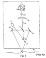
- Fig. 1 a synchronous optical triangulation scanning system that functions in accordance with the teachings of Rioux, United States patent number 4,627,734 and is essentially alike in structure to the embodiment illustrated in FIG. 12 of such patent is shown.
- Fig. 1 is also exemplary of a color and profile detection scheme described in United States patent number 5,177,556 in the name of Rioux.
- a light source 2 e.g. an RGB laser, produces a beam 6 that contains well defined red, green and blue wavelengths of light. Together with fixed mirrors 10 one surface of an oscillating double-sided mirror 4 scans the beam 6 in the x direction and projects it toward an object 8.
- Light 7 received back from a point P on the target surface of the object 8 is returned by a further fixed mirror 10, the opposite surface of the mirror 4, and a lens 14 in the form of a return beam 12 that is imaged onto a position sensitive detector 18, e.g. a CCD.
- a position sensitive detector 18 e.g. a CCD.
- a device 16 Interposed in this beam 12 is a device 16 for dispersing the beam into separate return beams 12B, 12G, and 12R of the three primary colors.
- the dispersal device 16 can be a simple wedge, it is preferable to use either a double wedge, or other device that will achieve a collinear effect, at least for one of the beams, preferably the green beam.
- the beam 12G will be in a straight through continuation of the beam 12.
- the detector 18 measures the amplitudes A and the positions D of the respective beams to generate signals 17B, 17G, and 17R (not shown here). The position of any one of these signals indicates the range of the point P, i.e. the deviation of the point P in the Z direction.
- the detector 18 is slanted to this optical axis because the focal plane varies with range.
- any one , two or all of these signals can be used to measure the Z deviation. Usually the signal with the greatest amplitude is be chosen for this purpose. If the color of the object is such that one of these signals is absent or is too small to measure, the colors of the two remaining signals can be identified by their spacing from each other. In some instances this limitation of requiring a minimum of two signals relating to two colors or well defined wavelengths may be acceptable, however in other instances where only one well defined wavelength is present this system has been found to be inadequate. For example, if the object is absent of red or green, color information cannot be determined without apriori knowledge of the absence of red and green. In other instances where the object is grey and or dark, color information may not be accurately determined, due to the low-level of light available from each wavelength.
- a light source can comprise other well defined wavelengths ⁇ l .. ⁇ N . wherein complementary detectors are provided for detecting these wavelengths of light ⁇ l.. ⁇ N .
- FIG. 2 an embodiment of the invention is shown having means for directly extracting color information in the form of three photodiode detectors.
- Each of the photo detectors are conveniently positioned to receive one of red, green and blue light. Thus if only blue light is present, a photo detector in the path of the blue wavelengths will detect its intensity.
- This embodiment provides several advantages over the teachings of Rioux in United States patent number 5,177,556. It allows the detection of a single primary color in the absence of the other two; and it provides system for detecting profile information that is less sensitive to low light conditions.
- a light source in the form of an RGB laser 12 produces a beam 6 that contains well defined red, green and blue wavelengths. Together with fixed mirror 18 one surface of an oscillating double-sided mirror 16 scans the beam 6 in the x direction and projects it toward a target object 8. Light 7 received back from the target surface of the object 8 is returned by the further fixed mirror 20, the opposite side of the oscillating double sided mirror 16 and a lens 24 in the form of a return beam 13, a large portion of which is imaged onto an intensity sensitive detector 28, e.g. in the form of a charged coupled device (CCD) array.
- CCD charged coupled device
- Profile information is calculated in the same manner as is taught in prior art United States patent number 5,177,566 , however, the arrangement of this embodiment is capable in some instances of providing more light for detection by the detector 28, thus yielding better results when the object is dark or dark grey in color.
- a beam splitter 26 for splitting the beam 13 into two separate return beams 13a, and 13b.
- the beam 13a is transmitted through to the detector 28 and the beam 13b which may typically only be comprised of a few percent of the energy of the beam 13 is reflected and directed to a means 30 for determining the color content of the beam 13a.
- means 30 is comprised of a prism 32 for dispersing the beam into separate return beams 33R, 33B, and 33G of the three primary colors red, blue and green.
- the dispersal device 32 can be a simple prism, alternatively a diffractive element such as a grating or a holographic dispersive element could be used.
- Three detectors, 34R, 34B, and 34G, are positioned to receive the separate return beams 33R, 33B, and 33G respectively.
- Each detector is not only capable of determining the presence of one of the separate beams, but also provides an analog output signal that is representative of the intensity of a beam incident upon it; thus I(r), I(g) and I(b) are the intensity values for the red green and blue light that are recorded.
- the analog signals may more conveniently be stored as in a digital form for later processing.
- this arrangement allows a single color to be detected, in the absence of the other two colors.
- the beam 13a is a single beam of light comprised of most of the signal energy of the transmitted signal 6, and this concentrated energy is focused onto the CCD array 28 rather than being divided up into three separate beams directed at three separate areas.
- the light used to determine the positional information is not diluted and substantially all of the light present in a single beam, having considerable energy relative to the prior art scheme, is utilized; As a result, this scheme is more tolerant of low light conditions where the object is, for example, dark gray in color.
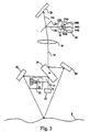
- Fig. 3 an alternative embodiment is shown that includes means in the form of normalization circuitry for eliminating some of the unwanted effects of noise present at the input on signal 6. Furthermore, this embodiment eliminates some of the unwanted effects due to fluctuations that may be present in the source light.
- a means to reduce the unwanted effect of noise present at the input of the scanning system is provided in the form of a circuit 23 that taps a small portion of the light generated by the light source 12 for illuminating the object, for monitoring purposes.
- a beam splitter 14 performs the tapping function however, most of the light generated by the laser source is transmitted to the oscillating double-sided mirror 16 as will be described.
- the circuit 23 further includes a prism 22 for dispersing/demultiplexing the tapped light into separate beams 5R, 5B, and 5G of the three primary colors red, blue and green. Of course, other wavelength demultiplexing means may be envisaged.
- Three separate monitoring detectors in the form of photodiodes 25R, 25B, and 25G are positioned to detect the intensity of the three separate beams.
- the circuit 23 is provided to monitor a small portion of the input light signal generated by the laser 12. By so doing, the small portion of monitored light can be used to eliminate noise present at the output that is a function of noise present at the input. This removal of noise is accomplished through a normalization process.
- the three monitoring photodiodes 25R, 25G, and 25B provide values I(R), I(G) and I(B) respectively, representing the intensity value for each color projected to the scene or object 8; these values are converted from analog to digital values and are stored in a computer memory for the purpose of color normalization.
- the normalization process essentially consists in determining a ratio by multiplying a constant with the detected input light and by dividing by the detected output light.
- this invention provides a more robust, accurate, and useful system, than the prior art has offered. Numerous other embodiments and variations of this invention may be envisaged. For example, designs based on the teachings of this invention may be contemplated, utilizing integrated circuitry and components, such as Bragg optical fiber gratings, or monolithic devices that include wavelength division demultiplexing and detecting capabilities.
Landscapes
- Physics & Mathematics (AREA)
- General Physics & Mathematics (AREA)
- Spectrometry And Color Measurement (AREA)
- Length Measuring Devices By Optical Means (AREA)
- Holo Graphy (AREA)
- Silicon Polymers (AREA)
- Image Input (AREA)
- Mechanical Optical Scanning Systems (AREA)
Claims (14)
- Optisches Verfahren zum Bestimmen der Farbe und Profiles einer Objektoberfläche mit folgenden Schritten:a) Abtasten der Objektoberfläche mit einem einfallendem Lichtstrahl, der eine Mehrzahl von Wellenlängen enthält, darunter mindestens eine wohl definierte Wellenlänge;b) Aufspalten eines Rückstrahles, der von der Objektoberfläche zurückgeworfen wurde, in eine Mehrzahl von getrennten Rückstrahlen, darunter mindestens ein erster und ein zweiter Rückstrahl;c) Verwenden des ersten Rückstrahles, der von der Objektoberfläche zurückgeworfen wurde, zur Bestimmung des Profites der Objektoberfläche; undd) Verwenden des zweiten Rückstrahles zur Ermittelung der Farbinformation, welche der Objektoberfläche entspricht.
- Verfahren zum Bestimmen der Farbe und des Profiles
einer Objektoberfläche gemäß Anspruch 1 mit dem weiteren Verfahrensschritt, dass der zweite Rückstrahl auf eine Einrichtung gegeben wird, welche den roten und/oder grünen und/oder blauen Anteil des ersten Strahles ermittelt. - Verfahren zum Bestimmen der Farbe und des Profiles
einer Objektoberfläche nach Anspruch 2 mit dem weiteren Schritt, dass Signale erzeugt werden, die für die Farbe der Objektoberfläche repräsentativ sind. - Verfahren zum Bestimmen der Farbe und des Profiles
einer Objektoberfläche nach Anspruch 3, welches die nachstehenden weiteren Schritte umfasst:i) Abtrennen eines Teiles des Lichtstrahles vor dem Abtasten der Objektoberfläche im Schritt a);ii) Überstellen des abgetrennten Teiles des Lichtstrahles zu einer Einrichtung, welche die spektrale Verteilung des abgetrennten Teiles des Lichtstrahles ermittelt und Signale erzeugt, die für die spektrale Verteilung des abgetrennten Teiles des Lichtstrahles repräsentativ sind;iii) Erzeugen der Signale, die für den Rotanteil, Grünanteil und Blauanteil des abgetrennten Teiles des Lichtstrahles repräsentativ sind; undiii) Bestimmen normierter Werte, die für die Farbe der Oberfläche repräsentativ sind, in Abhängigkeit von denjenigen Signalen die im Schritt (ii) erzeugt wurden und repräsentativ für die Farbe des abgetrennten Teiles des Lichtstrahles sind und der Signale, die repräsentativ für die Oberfläche sind. - Optisches Verfahren zum Bestimmen der Farbe und
des Profiles einer Objektoberfläche gemäß Anspruch 4, bei welchem der abgetrennte Lichtstrahl und der Strahl des auf die Objektoberfläche einfallenden Lichtes im Wesentlichen das Gleiche Verhältnis von rotem, grünem und blauem Licht aufweisen. - optisches Verfahren zum Bestimmen der Farbe und
der Profilinformation gemäß Anspruch 4, bei welchem der Schritt (ii) umfasst, dass der Rotanteil, Grünanteil und Blauanteil des abgetrennten Teiles des Strahles bestimmt wird und dazu verwendet wird, Signale zu erzeugen, die repräsentativ für den Rotanteil, Grünanteil und Blauanteil im abgetrennten Teil des Lichtstrahles sind. - Optisches Gerät zum Bestimmen der Farbe und des Profiles einer Objektoberfläche mita) einer Einrichtung zum Abtasten der Objektoberfläche mit einem einfallenden Lichtstrahl, der eine Mehrzahl von Wellenlängen enthält, darunter mindestens eine wohl definierte Wellenlänge;b) Mitteln zum Aufspalten des Rückstrahles, der von der Objektoberfläche zurückgeworfen wurde, in eine Mehrzahl getrennter Rückstrahlen, darunter zumindest ein erster und ein zweiter Rückstrahl;c) einer Einrichtung zum Bestimmen des Profiles der Objektoberfläche in Abhängigkeit von dem ersten Rückstrahl, der von der Objektoberfläche zurückgeworfen wurde; undd) einer Einrichtung zum Bestimmen der Farbinformation, welche der Objektoberfläche entspricht, aus dem zweiten Rückstrahl.
- Optisches Gerät zum Bestimmen der Farbe und des
Profiles einer Objektoberflache nach Anspruch 7 mit einer Einrichtung, durch welche das Rauschen herabgesetzt wird, welches an einem Einlass des Gerätes vorliegt. - Optisches Gerät zum Bestimmen der Farbe und des
Profiles einer Objektoberfläche nach Anspruch 8 miti) Mitteln zum Abtrennen eines Teiles des einfallenden Lichtstrahles, bevor die Objektoberfläche abgetastet wird, wobei diese Mittel im Stande sind, einen abgetrennten Lichtstrahl zu erzeugen;ii) einer Einrichtung zum Bestimmen der spektralen Verteilung des abgetrennten Strahles und zum Erzeugen von Signalen, die repräsentativ für die spektrale Verteilung des abgetrennten Teiles des Lichtstrahles sind; undiii) einer Einrichtung, welche in Abhängigkeit von den Signalen, die im Schritt (ii) ermittelt wurden und für die Farbe des abgetrennten Teiles des Lichtstrahles repräsentativ sind, und in Abhängigkeit von Signalen, die für die Farbe der Oberfläche repräsentativ sind, normierte Werte bestimmt, welche für die Farbe der Oberfläche repräsentativ sind. - Optisches Gerät zum Bestimmen der Farbe und des
Profiles einer Objektoberfläche nach Anspruch 7, bei welcher die Einrichtung zum Bestimmen der Farbinformation, welche der Objektoberfläche entspricht, zerlegungsmittel aufweist, welche den zweiten Rückstrahl entsprechend ihren Wellenlängen in eine Mehrzahl getrennter Strahlen auseinanderzieht. - Optisches Gerät zum Bestimmen der Farbe und des
Profiles einer Objektoberfläche nach Anspruch 10, bei welcher die Einrichtung zum Bestimmen der Farbinformation eine Mehrzahl von Detektoren aufweist, die beabstandet sind und so angeordnet sind, dass sie die Mehrzahl getrennter Strahlen erhalten. - Gerät zum Bestimmen der Farbe und des Profiles einer
Objektoberfläche nach Anspruch 9, bei welcher die Einrichtung zum Bestimmen der spektralen Verteilung (ii) den Rotanteil, Grünanteil und Blauanteil des abgetrennten Strahles bestimmen kann und Signale erzeugen kann, die für den Rotanteil, Grünanteil und Blauanteil des abgetrennten Teiles des Strahles repräsentativ sind. - Optisches Gerät zum Bestimmen der Farbe und des
Profiles einer Objektoberfläche nach Anspruch 12 mit Zerlegungsmitteln, welche den abgetrennten Strahl gemäß ihren Wellenlängen in eine Mehrzahl abgetrennter Strahlen zerlegt, und mit einer Mehrzahl von Detektoren, die beabstandet angeordnet sind, und die Mehrzahl getrennter abgetrennter Strahlen empfängt. - Optisches Gerät zum Bestimmen der Farbe und des
Profiles einer Objektoberfläche nach Anspruch 12, bei welcher die Einrichtung zum Bestimmen des Rotanteiles, Grünanteiles und Blauanteiles des abgetrennten Strahles und zum Erzeugen von Signalen, die für den Rotanteil, Grünanteil und Blauanteil des abgetrennten Teiles des Strahles repräsentativ sind, Zerlegungsmittel aufwallt?, welche den abgetrennten Strahl gemäß ihren Wellenlängen in eine Mehrzahl getrennter abgetrennter Strahlen zerlegt und eine Mehrzahl beabstandeter Detektoren umfasst, die von einander entfernt angeordnet sind und so stehen, dass sie die Mehrzahl getrennter abgetrennter Strahlen empfangen.
Applications Claiming Priority (3)
| Application Number | Priority Date | Filing Date | Title |
|---|---|---|---|
| US608006 | 1996-03-04 | ||
| US08/608,006 US5708498A (en) | 1996-03-04 | 1996-03-04 | Three dimensional color imaging |
| PCT/CA1997/000145 WO1997033139A1 (en) | 1996-03-04 | 1997-02-26 | Three-dimensional color imaging |
Publications (2)
| Publication Number | Publication Date |
|---|---|
| EP0885374A1 EP0885374A1 (de) | 1998-12-23 |
| EP0885374B1 true EP0885374B1 (de) | 2002-05-29 |
Family
ID=24434639
Family Applications (1)
| Application Number | Title | Priority Date | Filing Date |
|---|---|---|---|
| EP97903190A Expired - Lifetime EP0885374B1 (de) | 1996-03-04 | 1997-02-26 | Dreidimensionale farbbildaufnahme |
Country Status (7)
| Country | Link |
|---|---|
| US (1) | US5708498A (de) |
| EP (1) | EP0885374B1 (de) |
| JP (1) | JP3979670B2 (de) |
| AT (1) | ATE218202T1 (de) |
| CA (1) | CA2198283C (de) |
| DE (1) | DE69712872T2 (de) |
| WO (1) | WO1997033139A1 (de) |
Families Citing this family (26)
| Publication number | Priority date | Publication date | Assignee | Title |
|---|---|---|---|---|
| DE19831612A1 (de) | 1998-07-14 | 2000-01-20 | Voith Sulzer Papiermasch Gmbh | Meßsystem |
| US6522797B1 (en) | 1998-09-01 | 2003-02-18 | Input/Output, Inc. | Seismic optical acoustic recursive sensor system |
| US6122062A (en) * | 1999-05-03 | 2000-09-19 | Fanuc Robotics North America, Inc. | 3-D camera |
| US6507036B1 (en) | 1999-06-01 | 2003-01-14 | National Research Council Of Canada | Three dimensional optical scanning |
| DE19956646C1 (de) * | 1999-11-25 | 2001-10-18 | Dieter Dirksen | Vorrichtung und Verfahren zur Erfassung der Raumkoordinaten von farblich differenzierten Oberflächenmerkmalen |
| US6483595B1 (en) * | 2000-07-22 | 2002-11-19 | Basis Software, Inc. | Three dimensional optical scanner |
| US6639684B1 (en) | 2000-09-13 | 2003-10-28 | Nextengine, Inc. | Digitizer using intensity gradient to image features of three-dimensional objects |
| US7233351B1 (en) | 2001-02-23 | 2007-06-19 | Nextengine, Inc. | Method for high resolution incremental imaging |
| KR100406843B1 (ko) * | 2001-04-06 | 2003-11-21 | (주) 인텍플러스 | 색정보를 이용한 실시간 3차원 표면형상 측정방법 및 장치 |
| US20020163573A1 (en) * | 2001-04-11 | 2002-11-07 | Bieman Leonard H. | Imaging system |
| US6661953B2 (en) * | 2001-06-28 | 2003-12-09 | Avanex Corporation | Method and apparatus for simultaneous multiplexing and demultiplexing, variable attenuation and power detection of wavelength division multiplexed optical signals |
| JP2003240521A (ja) * | 2002-02-21 | 2003-08-27 | Bridgestone Corp | 被検体の外観・形状検査方法とその装置、及び、被検体の外観・形状検出装置 |
| US20040217956A1 (en) * | 2002-02-28 | 2004-11-04 | Paul Besl | Method and system for processing, compressing, streaming, and interactive rendering of 3D color image data |
| US20040119833A1 (en) * | 2002-07-25 | 2004-06-24 | Duncan Donald D. | Three-dimensional context sensitive scanner |
| US7302174B2 (en) | 2003-12-31 | 2007-11-27 | Symbol Technologies, Inc. | Method and apparatus for capturing images using a color laser projection display |
| US7711179B2 (en) | 2004-04-21 | 2010-05-04 | Nextengine, Inc. | Hand held portable three dimensional scanner |
| EP1610091A1 (de) * | 2004-06-23 | 2005-12-28 | Leica Geosystems AG | Scannersystem und Verfahren zur Erfassung von Oberflächen |
| DE102004034160A1 (de) * | 2004-07-15 | 2006-02-09 | Byk Gardner Gmbh | Vorrichtung zur Untersuchung optischer Oberflächeneigenschaften |
| US20060045174A1 (en) * | 2004-08-31 | 2006-03-02 | Ittiam Systems (P) Ltd. | Method and apparatus for synchronizing a transmitter clock of an analog modem to a remote clock |
| US7995834B1 (en) | 2006-01-20 | 2011-08-09 | Nextengine, Inc. | Multiple laser scanner |
| KR100722245B1 (ko) * | 2006-03-23 | 2007-05-29 | 주식회사 고영테크놀러지 | 3차원형상 측정장치 |
| US9178387B2 (en) * | 2008-05-13 | 2015-11-03 | Qualcomm Incorporated | Receive antenna for wireless power transfer |
| US8339616B2 (en) * | 2009-03-31 | 2012-12-25 | Micrometric Vision Technologies | Method and apparatus for high-speed unconstrained three-dimensional digitalization |
| US9262809B2 (en) | 2013-04-12 | 2016-02-16 | Centre De Recherche Industrielle Du Quebec | Method and apparatus for image noise filtering |
| US9427137B2 (en) * | 2013-05-15 | 2016-08-30 | Koninklijke Philips N.V. | Imaging a patient's interior |
| US11025800B2 (en) | 2018-04-13 | 2021-06-01 | Arius Technology Inc. | Systems and methods for imaging fine art paintings |
Family Cites Families (5)
| Publication number | Priority date | Publication date | Assignee | Title |
|---|---|---|---|---|
| DE2903529A1 (de) * | 1979-01-31 | 1980-08-07 | Schlatter Ag | Verfahren zum messen von entfernungen und vorrichtung zur durchfuehrung des verfahrens |
| US4349277A (en) * | 1980-06-11 | 1982-09-14 | General Electric Company | Non-contact measurement of surface profile |
| US4627734A (en) * | 1983-06-30 | 1986-12-09 | Canadian Patents And Development Limited | Three dimensional imaging method and device |
| US4946281A (en) * | 1989-04-24 | 1990-08-07 | General Motors Corporation | Laser profiler for high precision surface dimensional grouping apparatus and method |
| CA2017518A1 (en) * | 1990-05-24 | 1991-11-24 | Her Majesty The Queen, In Right Of Canada, As Represented By The Ministe R Of The National Research Council Of Canada | Colour-range imaging |
-
1996
- 1996-03-04 US US08/608,006 patent/US5708498A/en not_active Expired - Lifetime
-
1997
- 1997-02-17 CA CA002198283A patent/CA2198283C/en not_active Expired - Lifetime
- 1997-02-26 AT AT97903190T patent/ATE218202T1/de not_active IP Right Cessation
- 1997-02-26 JP JP53127897A patent/JP3979670B2/ja not_active Expired - Fee Related
- 1997-02-26 EP EP97903190A patent/EP0885374B1/de not_active Expired - Lifetime
- 1997-02-26 DE DE69712872T patent/DE69712872T2/de not_active Expired - Lifetime
- 1997-02-26 WO PCT/CA1997/000145 patent/WO1997033139A1/en active IP Right Grant
Also Published As
| Publication number | Publication date |
|---|---|
| US5708498A (en) | 1998-01-13 |
| EP0885374A1 (de) | 1998-12-23 |
| JP3979670B2 (ja) | 2007-09-19 |
| CA2198283C (en) | 2001-03-27 |
| DE69712872D1 (de) | 2002-07-04 |
| JP2000506970A (ja) | 2000-06-06 |
| ATE218202T1 (de) | 2002-06-15 |
| CA2198283A1 (en) | 1997-09-04 |
| WO1997033139A1 (en) | 1997-09-12 |
| DE69712872T2 (de) | 2002-11-28 |
Similar Documents
| Publication | Publication Date | Title |
|---|---|---|
| EP0885374B1 (de) | Dreidimensionale farbbildaufnahme | |
| EP1126412B1 (de) | Bilderfassungsgerät und Abstandsmessverfahren | |
| EP0458168B1 (de) | Dreidimensionale Farbbildaufnahme | |
| EP0997748B1 (de) | Chromatischer optischer Sensor zum Entfernungsmessen | |
| US5666195A (en) | Efficient fiber coupling of light to interferometric instrumentation | |
| US4899041A (en) | Light sensor for detecting an object in a certain distance | |
| US6507036B1 (en) | Three dimensional optical scanning | |
| US20020040971A1 (en) | Distance information obtaining apparatus and distance information obtaining method | |
| US6765606B1 (en) | Three dimension imaging by dual wavelength triangulation | |
| EP0302512B1 (de) | Vereinfachte Kalibrierung für eine Entfernungsinformationserwerbungsvorrichtung | |
| EP0882211B1 (de) | Verfahren und apparat zur reduzierung von unerwünschten rauscheffekten in einem dreidimensionalen farbbilderzeugungssystem | |
| US6327041B1 (en) | Method and device for opto-electrical acquisition of shapes by axial illumination | |
| JPH0670592B2 (ja) | コンパクト連続波波面センサー | |
| US5278402A (en) | Real-scene dispersion sensor detecting two wavelengths and determining time delay | |
| US4465366A (en) | Device for the photoelectric determination of the position of at least one focal plane of an image | |
| JP4266286B2 (ja) | 距離情報取得装置、および距離情報取得方法 | |
| CA2043336C (en) | Three dimensional colour imaging | |
| US4533828A (en) | Arrangement for increasing the dynamic range of optical inspection devices to accommodate varying surface reflectivity characteristics | |
| Beraldin et al. | VLSI laser spot sensors for 3D digitization | |
| JPH0812056B2 (ja) | 相対姿勢測定装置 | |
| JPH07139923A (ja) | 3次元物体計測装置 | |
| JPH01250778A (ja) | 光学検出装置 | |
| JPH08136249A (ja) | 距離検出装置 | |
| JPH0682662A (ja) | 受光モジュール |
Legal Events
| Date | Code | Title | Description |
|---|---|---|---|
| PUAI | Public reference made under article 153(3) epc to a published international application that has entered the european phase |
Free format text: ORIGINAL CODE: 0009012 |
|
| 17P | Request for examination filed |
Effective date: 19980902 |
|
| AK | Designated contracting states |
Kind code of ref document: A1 Designated state(s): AT BE CH DE DK ES FI FR GB GR IE IT LI LU MC NL PT SE |
|
| RIN1 | Information on inventor provided before grant (corrected) |
Inventor name: FOURNIER, PAUL Inventor name: KING, LAWRENCE Inventor name: RIOUX, MARC |
|
| GRAG | Despatch of communication of intention to grant |
Free format text: ORIGINAL CODE: EPIDOS AGRA |
|
| 17Q | First examination report despatched |
Effective date: 20010529 |
|
| GRAG | Despatch of communication of intention to grant |
Free format text: ORIGINAL CODE: EPIDOS AGRA |
|
| GRAH | Despatch of communication of intention to grant a patent |
Free format text: ORIGINAL CODE: EPIDOS IGRA |
|
| GRAH | Despatch of communication of intention to grant a patent |
Free format text: ORIGINAL CODE: EPIDOS IGRA |
|
| GRAA | (expected) grant |
Free format text: ORIGINAL CODE: 0009210 |
|
| AK | Designated contracting states |
Kind code of ref document: B1 Designated state(s): AT BE CH DE DK ES FI FR GB GR IE IT LI LU MC NL PT SE |
|
| PG25 | Lapsed in a contracting state [announced via postgrant information from national office to epo] |
Ref country code: NL Free format text: LAPSE BECAUSE OF FAILURE TO SUBMIT A TRANSLATION OF THE DESCRIPTION OR TO PAY THE FEE WITHIN THE PRESCRIBED TIME-LIMIT Effective date: 20020529 Ref country code: GR Free format text: LAPSE BECAUSE OF FAILURE TO SUBMIT A TRANSLATION OF THE DESCRIPTION OR TO PAY THE FEE WITHIN THE PRESCRIBED TIME-LIMIT Effective date: 20020529 Ref country code: FI Free format text: LAPSE BECAUSE OF FAILURE TO SUBMIT A TRANSLATION OF THE DESCRIPTION OR TO PAY THE FEE WITHIN THE PRESCRIBED TIME-LIMIT Effective date: 20020529 Ref country code: BE Free format text: LAPSE BECAUSE OF FAILURE TO SUBMIT A TRANSLATION OF THE DESCRIPTION OR TO PAY THE FEE WITHIN THE PRESCRIBED TIME-LIMIT Effective date: 20020529 Ref country code: AT Free format text: LAPSE BECAUSE OF FAILURE TO SUBMIT A TRANSLATION OF THE DESCRIPTION OR TO PAY THE FEE WITHIN THE PRESCRIBED TIME-LIMIT Effective date: 20020529 |
|
| REF | Corresponds to: |
Ref document number: 218202 Country of ref document: AT Date of ref document: 20020615 Kind code of ref document: T |
|
| REG | Reference to a national code |
Ref country code: GB Ref legal event code: FG4D |
|
| REG | Reference to a national code |
Ref country code: CH Ref legal event code: EP |
|
| REG | Reference to a national code |
Ref country code: IE Ref legal event code: FG4D |
|
| REF | Corresponds to: |
Ref document number: 69712872 Country of ref document: DE Date of ref document: 20020704 |
|
| PG25 | Lapsed in a contracting state [announced via postgrant information from national office to epo] |
Ref country code: PT Free format text: LAPSE BECAUSE OF FAILURE TO SUBMIT A TRANSLATION OF THE DESCRIPTION OR TO PAY THE FEE WITHIN THE PRESCRIBED TIME-LIMIT Effective date: 20020829 Ref country code: DK Free format text: LAPSE BECAUSE OF FAILURE TO SUBMIT A TRANSLATION OF THE DESCRIPTION OR TO PAY THE FEE WITHIN THE PRESCRIBED TIME-LIMIT Effective date: 20020829 |
|
| REG | Reference to a national code |
Ref country code: CH Ref legal event code: NV Representative=s name: FREI PATENTANWALTSBUERO |
|
| ET | Fr: translation filed | ||
| NLV1 | Nl: lapsed or annulled due to failure to fulfill the requirements of art. 29p and 29m of the patents act | ||
| PG25 | Lapsed in a contracting state [announced via postgrant information from national office to epo] |
Ref country code: ES Free format text: LAPSE BECAUSE OF FAILURE TO SUBMIT A TRANSLATION OF THE DESCRIPTION OR TO PAY THE FEE WITHIN THE PRESCRIBED TIME-LIMIT Effective date: 20021128 |
|
| PG25 | Lapsed in a contracting state [announced via postgrant information from national office to epo] |
Ref country code: LU Free format text: LAPSE BECAUSE OF NON-PAYMENT OF DUE FEES Effective date: 20030226 |
|
| PG25 | Lapsed in a contracting state [announced via postgrant information from national office to epo] |
Ref country code: MC Free format text: LAPSE BECAUSE OF NON-PAYMENT OF DUE FEES Effective date: 20030228 |
|
| PLBE | No opposition filed within time limit |
Free format text: ORIGINAL CODE: 0009261 |
|
| STAA | Information on the status of an ep patent application or granted ep patent |
Free format text: STATUS: NO OPPOSITION FILED WITHIN TIME LIMIT |
|
| 26N | No opposition filed |
Effective date: 20030303 |
|
| PGFP | Annual fee paid to national office [announced via postgrant information from national office to epo] |
Ref country code: IE Payment date: 20120217 Year of fee payment: 16 Ref country code: CH Payment date: 20120116 Year of fee payment: 16 Ref country code: FR Payment date: 20120227 Year of fee payment: 16 |
|
| PGFP | Annual fee paid to national office [announced via postgrant information from national office to epo] |
Ref country code: DE Payment date: 20120221 Year of fee payment: 16 |
|
| PGFP | Annual fee paid to national office [announced via postgrant information from national office to epo] |
Ref country code: GB Payment date: 20120221 Year of fee payment: 16 Ref country code: SE Payment date: 20120217 Year of fee payment: 16 Ref country code: IT Payment date: 20120227 Year of fee payment: 16 |
|
| REG | Reference to a national code |
Ref country code: CH Ref legal event code: PL |
|
| REG | Reference to a national code |
Ref country code: SE Ref legal event code: EUG |
|
| GBPC | Gb: european patent ceased through non-payment of renewal fee |
Effective date: 20130226 |
|
| PG25 | Lapsed in a contracting state [announced via postgrant information from national office to epo] |
Ref country code: CH Free format text: LAPSE BECAUSE OF NON-PAYMENT OF DUE FEES Effective date: 20130228 Ref country code: SE Free format text: LAPSE BECAUSE OF NON-PAYMENT OF DUE FEES Effective date: 20130227 Ref country code: LI Free format text: LAPSE BECAUSE OF NON-PAYMENT OF DUE FEES Effective date: 20130228 |
|
| REG | Reference to a national code |
Ref country code: FR Ref legal event code: ST Effective date: 20131031 |
|
| REG | Reference to a national code |
Ref country code: IE Ref legal event code: MM4A |
|
| REG | Reference to a national code |
Ref country code: DE Ref legal event code: R119 Ref document number: 69712872 Country of ref document: DE Effective date: 20130903 |
|
| PG25 | Lapsed in a contracting state [announced via postgrant information from national office to epo] |
Ref country code: IT Free format text: LAPSE BECAUSE OF NON-PAYMENT OF DUE FEES Effective date: 20130226 |
|
| PG25 | Lapsed in a contracting state [announced via postgrant information from national office to epo] |
Ref country code: DE Free format text: LAPSE BECAUSE OF NON-PAYMENT OF DUE FEES Effective date: 20130903 Ref country code: FR Free format text: LAPSE BECAUSE OF NON-PAYMENT OF DUE FEES Effective date: 20130228 Ref country code: GB Free format text: LAPSE BECAUSE OF NON-PAYMENT OF DUE FEES Effective date: 20130226 Ref country code: IE Free format text: LAPSE BECAUSE OF NON-PAYMENT OF DUE FEES Effective date: 20130226 |