EP0885084B1 - Reflow soldering apparatus with a rotative configuration - Google Patents
Reflow soldering apparatus with a rotative configuration Download PDFInfo
- Publication number
- EP0885084B1 EP0885084B1 EP96927943A EP96927943A EP0885084B1 EP 0885084 B1 EP0885084 B1 EP 0885084B1 EP 96927943 A EP96927943 A EP 96927943A EP 96927943 A EP96927943 A EP 96927943A EP 0885084 B1 EP0885084 B1 EP 0885084B1
- Authority
- EP
- European Patent Office
- Prior art keywords
- chambers
- objects
- chamber
- disc
- processing
- Prior art date
- Legal status (The legal status is an assumption and is not a legal conclusion. Google has not performed a legal analysis and makes no representation as to the accuracy of the status listed.)
- Expired - Lifetime
Links
Images


Classifications
-
- B—PERFORMING OPERATIONS; TRANSPORTING
- B23—MACHINE TOOLS; METAL-WORKING NOT OTHERWISE PROVIDED FOR
- B23K—SOLDERING OR UNSOLDERING; WELDING; CLADDING OR PLATING BY SOLDERING OR WELDING; CUTTING BY APPLYING HEAT LOCALLY, e.g. FLAME CUTTING; WORKING BY LASER BEAM
- B23K3/00—Tools, devices, or special appurtenances for soldering, e.g. brazing, or unsoldering, not specially adapted for particular methods
- B23K3/04—Heating appliances
Definitions
- the invention relates to an apparatus for reflow soldering objects, wherein the apparatus comprises:
- the chambers are each fixed and they are each arranged for performing a defined process on the objects.
- This object is achieved in that the chambers are moveable in accordance with a closed circuit and that the processing devices are adapted to perform a process on the object which is present in a chamber present in a defined position.
- the apparatus is adapted to cause the chambers to move substantially through a rectangular path.
- the chambers are arranged fixedly and transport means are arranged for transporting the objects for processing and processed objects in and out of the chambers.
- transport means are arranged for transporting the objects for processing and processed objects in and out of the chambers.
- the apparatus is adapted according to a preferred embodiment to perform a temperature treatment on objects.
- the heat treatments for performing with the apparatus according to the invention are not limited to reflow soldering; a synthetic resin can likewise be cured with the apparatus.
- the apparatus is also however also possible for the apparatus to be adapted to perform other processes on objects for processing, for instance processing the objects with a chemical substance.
- An example of such a process is cleaning objects by means of a plasma, in particular at least partially metal objects, for example printed circuit boards.
- heating means in for instance the form of IR light sources which are adapted to heat by means of radiation the objects for heating which are present inside the chamber.
- This embodiment is of particular importance when the process to which the objects for processing must be subjected requires a large positive temperature gradient which cannot be achieved with the supply means for supplying heated gas.
- the two types of heating can of course be combined.
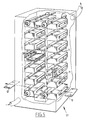
- FIG 1 a reflow soldering apparatus 1 which forms part of a processing line, which also includes for instance so-called "pick and place” machines.
- the soldering apparatus is essentially formed by a frame which is formed inter alia by a first trestle 2, a second trestle 3 and a bearing plate 4 which rests on the ground by means of a frame part not shown in the drawing.
- a first rotation shaft 5 is mounted in the first trestle 2 and bearing plate 4, while a second rotation shaft 6 is mounted in trestle 3 and bearing plate 4.
- the rotation shafts 5, 6 are parallel but do not extend mutually in line.
- On rotation shaft 5 is arranged a first support member 7 which has a substantially star-shaped configuration.
- This support member is formed essentially by a plate 8 which is mounted on shaft 5 and to which hollow, radially extending arms 9 are fixed in the manner of a star 7.
- a disc, not shown in figure 1 to which are fixed hollow arms 10 is arranged on shaft 6.
- the hollow arms 9,10 extend in each case in pairs parallel to each other.
- a box 11 is arranged between each pair of parallel extending arms 9,10.
- the number of boxes is thus equal to the number of pairs of arms. Because of the fact that shafts 5,6 are displaced relatively of each other, the rotation points at which the boxes 11 are each rotatably connected to arms 9,10 are also each displaced relative to each other, so that as a result of this displacement the boxes 11 are always situated with their base plane horizontal.
- printed circuit boards in the relevant boxes 11 use is made of a conveyor belt 12. This latter supplies the printed circuit boards 13 for processing.
- Printed circuit boards 13 are transported into boxes 11 by means of the long side 14 of each of the boxes 11 which is moveable outward as shown in figure 1.
- the relevant side 14 is herein fixed to carriers arranged in the box which are outwardly moveable over guide rails 16 arranged in the box to the position shown in figure 1.
- the printed circuit boards 13 for processing can be transported by means of the transport device 12 onto the carriers 15.
- the conveyor belt is arranged such that it lies in line with carriers 15. Since the conveyor belt is generally unable to cause the printed circuit boards 13 for processing to move in their entirety onto carriers 15, use is made of a pushing element not shown in the drawing, the direction of which is parallel to the transport direction.
- both printed circuit boards 13 for processing have been arranged on carrier 15, the carriers including wall 14 are moved inward in the present case by means of an external linear drive mechanism 17, wherein the box is closed.
- a gas-tight seal is arranged for this purpose between the side 14 of the box and the actual box 11 itself. This also prevents O 2 entering the box.
- the carrier 15, including the side 14 is moved outward by means of the external drive mechanism 17 until carrier 15 is situated in line with conveyor belt 12.
- the conveyor belt 12 is then moved whereby the processed printed circuit boards are fed through by the transporting device to a subsequent processing station, and the printed circuit boards yet to be processed are transported onto carrier 15. Thereafter the cycle repeats itself. It is pointed out here that instead of the shown number of two printed circuit boards, it is also possible for only one printed circuit board to be received into a box or for a larger number of printed circuit boards to be used.
- the carrier 15 is formed by two rails (not shown in the drawing) extending in the transport direction of the conveyor belt. So as to take account of printed circuit boards of differing width one of the rails is adjustable in the transverse direction.
- a separate drive device can be arranged in each of the boxes 11 for this purpose. However, it is also possible to arrange the drive device fixedly between two pushers 17. The width between the rails can then only be adjusted by means of coupling from the box 11 situated in the loading position.
- rotational driving of the whole unit takes place intermittently; i.e. the apparatus stands still for a period of time, which period is of course co-determined by the length of the operations which must be performed for emptying respectively filling boxes 11 and of course also by the length of operations to be performed.
- the arms 9 are provided with a flat side 18 which is continued beyond the end of the hollow part. This also applies to hollow arms 10.
- a pipe piece 19 which extends in axial direction of the rotation shafts 5,6 and which is connected to the hollow part of the arms 9 and 10 respectively by means of an elbow 20 manufactured from flexible material. It is of course possible to make use of rigid elbows instead of elbows made of flexible material.
- the pipe pieces 19 serve not only as guide for the gases supplied through the hollow arms 9 and the gases for discharging through the hollow arms 10, but also as rotation shaft for the rotatable suspension of boxes 11.
- the boxes 11 are provided with a pipe end part 21 which is mounted on pipe piece 19 by means of a bearing 22.
- the bearing is further connected to a rotating seal 23 to seal off the gas flow relative to the environment.
- a corresponding construction is arranged on the side of the hollow arm 10.
- a wall system 24 is further arranged for distributing the incoming gas flow in the boxes 11.
- This wall system which is provided with holes (not shown in the drawing) arranged therein, ensures a good distribution of the supplied gases over the printed circuit boards for pre-heating. This produces the most uniform possible heating of the printed circuit boards and the components present thereon, which of course enhances the quality of the solder connections.
- hollow arms 9 are in communication with the holes 25 arranged in disc 8.
- a second disc 26 which is again mounted on shaft 5 and which, in contrast to disc 8, is freely rotatable relative to shaft 5.
- openings 27 which in the present case correspond in diameter and shape with the openings 25.
- pipe end parts 28 which are connected by means of flexible hoses 29 to generators for generating and supplying gas of the required temperature. These generators are not shown in the drawing. It is of course possible to make use of air as convection gas.
- inert gas for instance nitrogen. This is of course also the case for other applications. This is well possible due to the good sealing of the boxes 11, the rotating seals 22 and so on. The advantages of the smaller volume of the boxes and ducts are particularly emphasized in the case of an inert gas.
- the normal position of the disc 26 is chosen such that the holes 28 arranged in the first disc 8 always correspond with holes 27 arranged in the second disc 26, so that no choking of the gas flow occurs. It is of course ensured here that the correct generator is connected by means of the relevant hose 29 and to the pipe end part 28, which gives a connection to the box 11 situated in the relevant position. So as to avoid any problem of choke effects during rotation of the whole assembly of arms 9,10 and boxes 11 arranged thereon, the disc 26 co-displaces with the rotation of the disc 8 for a large part of the relevant movement. For this purpose the disc 26 is driven in rotation by an air cylinder 30 connected thereto which is connected to disc 26 by means of a bracket 31.
- a corresponding component is arranged for the discharge of the gas coming from the relevant chamber to the generator corresponding therewith for reheating and optionally filtering the relevant gas.
- the above described embodiment relates to an embodiment operating with convection; it is otherwise possible to cause the heating process to take place using radiation, in particular IR radiation. IR radiation elements must be built into the boxes for this purpose. It is moreover also possible to combine heating by convection with heating by radiation.
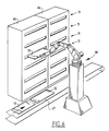
- FIG 4 an apparatus 40 is shown wherein the boxes 11 are driven in a substantially rectangular path.
- Use is made for this purpose of two schematically shown transporting chains 41 respectively 42 which are each trained around guide wheels 43a-d and 44a-d respectively. At least one of four guide wheels is herein driven at a time.
- the chains 41, 42 are always mutually connected by rods 45.
- a chamber 11 is fixed to each of the rods by means of suspension brackets 46.
- the suspension brackets 46 are constructed such that chambers 11 can rotate relative to rod 45; this is in any case necessary in order to hold the chambers 11 at all times in the horizontal position.
- guide means for further guiding of the chambers 11 use can be made of guide means (not shown in the drawing).
- boxes 47,48,49 For respectively feeding gases to chambers 11 and for discharging gases from chambers 11 use is made of boxes 47,48,49 respectively and a box not shown in the drawing located on either side of the chains. These boxes extend parallel to the vertical parts of the path, wherein boxes 47-49 are each subdivided into separate spaces by means of partitions 50.
- a supply line 51 for supplying gas is connected to each of the boxes of chambers 47,48. This will generally be heated gas for heating objects present in chambers 11, but can also be formed by cooled gas for exercising a cooling function.
- the boxes 49 and the box which is not shown are thus connected on the other side to discharge ducts 52 for discharging the gas which has performed the process.
- Elongate openings 53 are arranged in each of the spaces for supplying the gases to the boxes. These openings connect to gas guide pieces (not shown in figure 4) fixed to each of the boxes 11.
- gas guiding elements 54 which are shown in the drawings and which are arranged on the other side of chambers 11 and which connect to openings arranged in box 49.
- both holes 25 and openings 53 are elongate, a coupling is created over a rather long path between the relevant gas supply line 51, box 11 and gas discharge line 52.
- the time durations and ratios can be adapted to the relevant requirements, wherein it can also be ensured that no short circuit occurs in the path of the gas.
- box 49 and the box not shown here can thus be arranged on the same side of the apparatus as boxes 47 and 48. It is also possible, as shown, to allow the boxes to also extend on the underside, i.e. relating to the horizontal part of the path.
- gas distribution device shown in figure 3 can thus be used for instance, wherein flexible hoses will have to provide a connection between holes 25 and the relevant chambers.
- the disc 26 will also have to driven synchronously with the drive device of the chains.
- a similar configuration can also be used for the gas discharge device.
- FIG. 5 shows an apparatus 57 which corresponds for the most part with the apparatus shown in figure 4.
- this apparatus shown in figure 5 there are no gas supply and discharge lines but processing devices incorporated in the chambers 11 themselves.
- a pair of infra red lamps 58 which have an output such that the objects present in boxes 11 can be heated to a sufficient degree therewith.
- a fan 59 is also arranged to obtain a good heat distribution.
- boxes 11 are each provided with sliding contacts 60,61 which slide along conductor paths 62 respectively 63 disposed parallel to the path of chain conveyor 41. This ensures the electrical energy supply to the electrical appliances arranged in boxes 11.
- the choice of the position at which the heating device can be connected can of course also be made by selecting the position of both contact rails 62,63.
- the apparatus is provided with a video camera which is directed at the interior of one of the boxes.
- This camera can be disposed fixedly and be connected to box 11 via a glass fibre, but can also be fixed in the box. This offers the possibility of visually observing the processes taking place in the box.
- thermocouples in the box 11 which are connected by needles to the positions on the printed circuit board with which it is wished to measure the temperature.
- the chambers are exposed to large temperature-time gradients, it is important that the chambers be manufactured from a material with a small heat capacity; this results in any case in a lower energy consumption and a shorter time constant.
Landscapes
- Engineering & Computer Science (AREA)
- Mechanical Engineering (AREA)
- Electric Connection Of Electric Components To Printed Circuits (AREA)
Abstract
Description
- a plurality of chambers which are each adapted to contain at least one object; and
- processing devices for processing objects present in the chambers, wherein the chambers are adapted to successively perform different processes on the objects present in the chamber.
Claims (30)
- Apparatus (1) for reflow soldering objects, wherein the apparatus comprises:a plurality of chambers (11) which are each adapted to contain at least one object (13); andprocessing devices (8,9,18-29) for processing objects (13) present in the chambers (11), wherein the chambers (11) are adapted to successively perform different processes on the objects (13) present in the chamber, characterized in that the chambers (11) are moveable in accordance with a closed circuit and that the processing devices (8,9,18-29) are adapted to perform a process on the object (13) which is present in a chamber (11) present in a defined position.
- Apparatus as claimed in claim 1, characterized by infeed and outfeed means (12,15,17) for carrying the objects (13) for processing into the chambers (11) and for carrying the processed objects (13) out of the chambers (11), wherein the infeed and outfeed means (12,15,17) are adapted to feed the objects in and out at only a single position of the chambers (11).
- Apparatus as claimed in claim 2, characterized in that the apparatus (1) comprises the transporting members (9,10;41,42) which are intermittently drivable.
- Apparatus as claimed in claim 1, 2 or 3, characterized in that the apparatus is adapted to cause the chambers (11) to move in accordance with a substantially circular path.
- Apparatus as claimed in claim 4, characterized in that the apparatus comprises at least two suspension members (9,10) each rotatable round a shaft (5,6), wherein each of the chambers (11) is fixed to both suspension members (9,10) and wherein the shafts (5,6) are mutually parallel.
- Apparatus as claimed in claim 5, characterized in that the shafts (5,6) extend in a horizontal plane.
- Apparatus as claimed in claim 6, characterized in that the shafts (5,6) are mutually displaced.
- Apparatus (40) as claimed in claim 1, 2 or 3, characterized in that the apparatus is adapted to cause the chambers (11) to move in accordance with a substantially rectangular path.
- Apparatus (40) as claimed in claim 8, characterized in that the chambers (11) are suspended on at least two flexible transporting members (41,42), for example belts or chains, which are guided over guide members (43a-d,44a-d), for instance wheels, and which are drivable.
- Apparatus as claimed in claim 9, characterized in that a third transporting member is arranged for holding the chambers (11) in the horizontal position.
- Apparatus as claimed in any of the foregoing claims, characterized in that the apparatus (1,40) is adapted to perform a temperature treatment on the objects (13).
- Apparatus as claimed in claim 11, characterized in that the apparatus (1,40) is adapted to at least partially perform the temperature treatment by means of supplying and discharging gases respectively to and from the chambers (11).
- Apparatus as claimed in claim 12, characterized in that the gas discharge means (29) are coupled to the gas supply means (29) to form a closed circuit.
- Apparatus as claimed in claim 12 or 13, characterized in that the apparatus comprises coupling means (8,25) for coupling individual gas supply and discharge means (29) to the chamber (11) subject to the position of a chamber.
- Apparatus as claimed in claims 4 and 14, characterized in that the coupling means (8,25) are adapted to couple individual gas supply and discharge means (29), subject to the rotational position of the suspension member (9,10), to ducts incorporated in the suspension member (9,10) and leading to the separate chambers (11).
- Apparatus as claimed in claim 15, characterized in that the coupling means comprise a disc (8) provided with holes (25), wherein the holes (25) are coupled to ducts (9,10) leading to the chambers (11) and comprise a second disc (26) which is disposed parallel to and abutting the first disc (25), which second disc (26) is provided with holes (28) which are coupled to respectively the gas supply and discharge means (29).
- Apparatus as claimed in claim 16, characterized in that the second disc (26) is coupled to a drive element (30) in order to cause the second disc (26) to perform an intermittent movement so as to cause the holes (25) in the first disc (8) to correspond with the holes (28) in the second disc (26) during as large a part of the movement as possible.
- Apparatus as claimed in claims 8 and 14, characterized in that the apparatus (40) comprises spaces (48,49,50) extending along the path of the chambers (11) which are each connectable to the chamber (11) situated in their vicinity by means of openings (25,53) arranged in the chambers (11) and in the spaces (48,49,50), which openings (25,53), when placed in register, form a connection between the chamber (11) and the closest spaces (48,49,50), and that at least a part of the spaces (48,49,50) is connected to gas supply (51) and discharge means (52) respectively.
- Apparatus as claimed in any of the foregoing claims, characterized in that the chambers (11) are adapted to perform re-circulation (59) of the gas inside the chamber.
- Apparatus as claimed in claim 19,
characterized in that in each of the chambers heating means (58) are arranged which are adapted to heat the gas present inside the chamber (11). - Apparatus as claimed in claim 20, characterized in that in each of the chambers (11) heating means, for example IR light sources (58), are arranged which are adapted to heat the objects (13) for heating present inside the chamber by means of radiation.
- Apparatus as claimed in any of the foregoing claims, characterized in that the chambers (11) are manufactured from material with a low heat capacity, for example plastic.
- Apparatus as claimed in any of the foregoing claims, characterized in that the chambers (11) are each provided on one side with a wall (14) which is moveable outward in the direction perpendicular to its plane.
- Apparatus as claimed in claims 1 and 23, characterized in that the moveable wall (14) is fixedly connected on its inner side to a carrier (12) for the objects (13) for processing and that the carrier (12) is coupled to guide means (15) arranged in the chamber (11) for guiding the carrier (12) and the wall (14).
- Apparatus as claimed in claim 24, characterized in that the carrier (12) is adapted to support objects (13) for processing with a different width in that the carrier (12) comprises at least two support elements which extend in the transporting direction of the conveyor belt and at least one of which is adjustable in the direction transversely of its length direction.
- Apparatus as claimed in claim 25, characterized in that in its extended position the carrier is (14) situated in the path of a transport member (12) for feed and discharge of the objects (13) for processing respectively the processed objects.
- Apparatus as claimed in claim 26,
characterized in that at least one adjustable support element (16) is provided with coupling means for driving by means of a fixedly disposed motor the adjusting movement of the at least one support element (16) when the carrier (14) is situated in the path of the transport member (12). - Apparatus as claimed in any of the foregoing claims, characterized in that the apparatus is provided with an observation system for observing the processes taking place in the boxes.
- Apparatus as claimed in claim 28, characterized in that the observation device comprises at least one video camera.
- Apparatus as claimed in claim 29, characterized in that the observation device comprises at least one temperature measuring device.
Applications Claiming Priority (5)
| Application Number | Priority Date | Filing Date | Title |
|---|---|---|---|
| NL1001089 | 1995-08-29 | ||
| NL1001089 | 1995-08-29 | ||
| NL1002175 | 1996-01-25 | ||
| NL1002175 | 1996-01-25 | ||
| PCT/NL1996/000341 WO1997007924A1 (en) | 1995-08-29 | 1996-08-28 | Reflow soldering apparatus with a rotative configuration |
Publications (2)
| Publication Number | Publication Date |
|---|---|
| EP0885084A1 EP0885084A1 (en) | 1998-12-23 |
| EP0885084B1 true EP0885084B1 (en) | 2001-07-25 |
Family
ID=26642160
Family Applications (1)
| Application Number | Title | Priority Date | Filing Date |
|---|---|---|---|
| EP96927943A Expired - Lifetime EP0885084B1 (en) | 1995-08-29 | 1996-08-28 | Reflow soldering apparatus with a rotative configuration |
Country Status (5)
| Country | Link |
|---|---|
| US (1) | US6096999A (en) |
| EP (1) | EP0885084B1 (en) |
| AT (1) | ATE203443T1 (en) |
| DE (1) | DE69614152T2 (en) |
| WO (1) | WO1997007924A1 (en) |
Families Citing this family (6)
| Publication number | Priority date | Publication date | Assignee | Title |
|---|---|---|---|---|
| US5965048A (en) * | 1998-11-20 | 1999-10-12 | General Electric Company | Heated chamber including an open wall with a gas curtain |
| US6354481B1 (en) | 1999-02-18 | 2002-03-12 | Speedline Technologies, Inc. | Compact reflow and cleaning apparatus |
| US9226407B2 (en) * | 2002-07-01 | 2015-12-29 | Semigear Inc | Reflow treating unit and substrate treating apparatus |
| DE102016222114A1 (en) * | 2016-11-10 | 2018-05-17 | Asm Assembly Systems Gmbh & Co. Kg | Heating system and method for performing a soldering operation in an SMT placement line |
| DE102019116290A1 (en) * | 2019-06-14 | 2020-12-17 | Werkzeugbau Siegfried Hofmann Gmbh | Device for soldering |
| DE102020119877A1 (en) * | 2020-07-28 | 2022-02-03 | Siegfried Hofmann Gmbh | Device for moving at least one assembly between a staging area and a work area |
Family Cites Families (7)
| Publication number | Priority date | Publication date | Assignee | Title |
|---|---|---|---|---|
| US1385662A (en) * | 1919-10-13 | 1921-07-26 | Nat System Of Bakeries Co | Baking-oven |
| US3272933A (en) * | 1964-07-10 | 1966-09-13 | Sperry Rand Corp | Rotary indexing programmer switch using circuit boards |
| GB1461494A (en) * | 1974-04-04 | 1977-01-13 | Asahi Glass Co Ltd | Apparatus and method for sealing components in tubes |
| US5101546A (en) * | 1990-11-30 | 1992-04-07 | Hitachi Seiko Ltd. | Apparatus for removing printed board |
| TW220028B (en) * | 1992-08-24 | 1994-02-01 | Ciba Geigy Ag | Method and apparatus for coating board-shaped articles, especially printed circuit boards |
| US5345061A (en) * | 1992-09-15 | 1994-09-06 | Vitronics Corporation | Convection/infrared solder reflow apparatus utilizing controlled gas flow |
| JP3250082B2 (en) * | 1992-09-30 | 2002-01-28 | エイテックテクトロン株式会社 | Automatic soldering equipment |
-
1996
- 1996-08-28 EP EP96927943A patent/EP0885084B1/en not_active Expired - Lifetime
- 1996-08-28 WO PCT/NL1996/000341 patent/WO1997007924A1/en active IP Right Grant
- 1996-08-28 US US09/029,420 patent/US6096999A/en not_active Expired - Fee Related
- 1996-08-28 DE DE69614152T patent/DE69614152T2/en not_active Expired - Fee Related
- 1996-08-28 AT AT96927943T patent/ATE203443T1/en not_active IP Right Cessation
Also Published As
| Publication number | Publication date |
|---|---|
| DE69614152D1 (en) | 2001-08-30 |
| US6096999A (en) | 2000-08-01 |
| WO1997007924A1 (en) | 1997-03-06 |
| ATE203443T1 (en) | 2001-08-15 |
| EP0885084A1 (en) | 1998-12-23 |
| DE69614152T2 (en) | 2001-11-15 |
Similar Documents
| Publication | Publication Date | Title |
|---|---|---|
| US8091759B2 (en) | Soldering machine comprising a soldering module and at least one soldering station that is mobile and exchangeable insertable into the soldering module | |
| EP0885084B1 (en) | Reflow soldering apparatus with a rotative configuration | |
| CA1048965A (en) | Apparatus for radiation curing of coating on a multi-sided object | |
| CN111282777B (en) | Coating and curing production line | |
| CN111420841A (en) | Online dip-coating device | |
| US4327665A (en) | Method and apparatus for coating composition on can seams | |
| KR200388410Y1 (en) | Drive apparatus of Roast machine | |
| US6147328A (en) | Apparatus for the heat treatment of workpieces | |
| KR20090054492A (en) | Heat treatment apparatus | |
| CN111299085B (en) | Online dip-coating curing device | |
| KR960010032B1 (en) | Work mounting apparatus | |
| US20020001787A1 (en) | Facility for the thermal treatment of workpieces | |
| CN110181268A (en) | A kind of electronic cigarette tobacco rod automatic assembly equipment | |
| JPH1043279A (en) | Sterilizing device | |
| US7857125B2 (en) | Apparatus having rotating chains or rings for carrying vertically hanging trays | |
| CN218982197U (en) | Curing mechanism and curing equipment | |
| CN219383983U (en) | Rotor carrying device | |
| JPH11100009A (en) | Carrying method and device for sterilizing treatment | |
| CN114593566A (en) | Drying equipment | |
| JP7466680B2 (en) | Sterilization module and trolley processing module | |
| CN214027787U (en) | Drying equipment for printed products | |
| CN218840665U (en) | Pipe conveying device | |
| KR200494881Y1 (en) | Insulating paint coating mechanism for resistor parts | |
| CN216568124U (en) | Coconut pulp sterilizing equipment | |
| CN216080799U (en) | Spraying drying device is used in block terminal production |
Legal Events
| Date | Code | Title | Description |
|---|---|---|---|
| PUAI | Public reference made under article 153(3) epc to a published international application that has entered the european phase |
Free format text: ORIGINAL CODE: 0009012 |
|
| 17P | Request for examination filed |
Effective date: 19980219 |
|
| AK | Designated contracting states |
Kind code of ref document: A1 Designated state(s): AT BE CH DE DK ES FI FR GB GR IE IT LI NL SE |
|
| 17Q | First examination report despatched |
Effective date: 19991019 |
|
| GRAG | Despatch of communication of intention to grant |
Free format text: ORIGINAL CODE: EPIDOS AGRA |
|
| GRAG | Despatch of communication of intention to grant |
Free format text: ORIGINAL CODE: EPIDOS AGRA |
|
| GRAH | Despatch of communication of intention to grant a patent |
Free format text: ORIGINAL CODE: EPIDOS IGRA |
|
| GRAH | Despatch of communication of intention to grant a patent |
Free format text: ORIGINAL CODE: EPIDOS IGRA |
|
| GRAA | (expected) grant |
Free format text: ORIGINAL CODE: 0009210 |
|
| AK | Designated contracting states |
Kind code of ref document: B1 Designated state(s): AT BE CH DE DK ES FI FR GB GR IE IT LI NL SE |
|
| PG25 | Lapsed in a contracting state [announced via postgrant information from national office to epo] |
Ref country code: NL Free format text: LAPSE BECAUSE OF FAILURE TO SUBMIT A TRANSLATION OF THE DESCRIPTION OR TO PAY THE FEE WITHIN THE PRESCRIBED TIME-LIMIT Effective date: 20010725 Ref country code: LI Free format text: LAPSE BECAUSE OF FAILURE TO SUBMIT A TRANSLATION OF THE DESCRIPTION OR TO PAY THE FEE WITHIN THE PRESCRIBED TIME-LIMIT Effective date: 20010725 Ref country code: IT Free format text: LAPSE BECAUSE OF FAILURE TO SUBMIT A TRANSLATION OF THE DESCRIPTION OR TO PAY THE FEE WITHIN THE PRE;WARNING: LAPSES OF ITALIAN PATENTS WITH EFFECTIVE DATE BEFORE 2007 MAY HAVE OCCURRED AT ANY TIME BEFORE 2007. THE CORRECT EFFECTIVE DATE MAY BE DIFFERENT FROM THE ONE RECORDED.SCRIBED TIME-LIMIT Effective date: 20010725 Ref country code: FR Free format text: LAPSE BECAUSE OF FAILURE TO SUBMIT A TRANSLATION OF THE DESCRIPTION OR TO PAY THE FEE WITHIN THE PRESCRIBED TIME-LIMIT Effective date: 20010725 Ref country code: FI Free format text: LAPSE BECAUSE OF FAILURE TO SUBMIT A TRANSLATION OF THE DESCRIPTION OR TO PAY THE FEE WITHIN THE PRESCRIBED TIME-LIMIT Effective date: 20010725 Ref country code: CH Free format text: LAPSE BECAUSE OF FAILURE TO SUBMIT A TRANSLATION OF THE DESCRIPTION OR TO PAY THE FEE WITHIN THE PRESCRIBED TIME-LIMIT Effective date: 20010725 Ref country code: BE Free format text: LAPSE BECAUSE OF FAILURE TO SUBMIT A TRANSLATION OF THE DESCRIPTION OR TO PAY THE FEE WITHIN THE PRESCRIBED TIME-LIMIT Effective date: 20010725 Ref country code: AT Free format text: LAPSE BECAUSE OF FAILURE TO SUBMIT A TRANSLATION OF THE DESCRIPTION OR TO PAY THE FEE WITHIN THE PRESCRIBED TIME-LIMIT Effective date: 20010725 |
|
| REF | Corresponds to: |
Ref document number: 203443 Country of ref document: AT Date of ref document: 20010815 Kind code of ref document: T |
|
| REG | Reference to a national code |
Ref country code: CH Ref legal event code: EP |
|
| REG | Reference to a national code |
Ref country code: IE Ref legal event code: FG4D |
|
| PG25 | Lapsed in a contracting state [announced via postgrant information from national office to epo] |
Ref country code: IE Free format text: LAPSE BECAUSE OF NON-PAYMENT OF DUE FEES Effective date: 20010828 |
|
| REF | Corresponds to: |
Ref document number: 69614152 Country of ref document: DE Date of ref document: 20010830 |
|
| PG25 | Lapsed in a contracting state [announced via postgrant information from national office to epo] |
Ref country code: SE Free format text: LAPSE BECAUSE OF FAILURE TO SUBMIT A TRANSLATION OF THE DESCRIPTION OR TO PAY THE FEE WITHIN THE PRESCRIBED TIME-LIMIT Effective date: 20011025 Ref country code: GB Free format text: LAPSE BECAUSE OF NON-PAYMENT OF DUE FEES Effective date: 20011025 Ref country code: DK Free format text: LAPSE BECAUSE OF FAILURE TO SUBMIT A TRANSLATION OF THE DESCRIPTION OR TO PAY THE FEE WITHIN THE PRESCRIBED TIME-LIMIT Effective date: 20011025 |
|
| PG25 | Lapsed in a contracting state [announced via postgrant information from national office to epo] |
Ref country code: GR Free format text: LAPSE BECAUSE OF FAILURE TO SUBMIT A TRANSLATION OF THE DESCRIPTION OR TO PAY THE FEE WITHIN THE PRESCRIBED TIME-LIMIT Effective date: 20011026 |
|
| EN | Fr: translation not filed | ||
| REG | Reference to a national code |
Ref country code: GB Ref legal event code: IF02 |
|
| NLV1 | Nl: lapsed or annulled due to failure to fulfill the requirements of art. 29p and 29m of the patents act | ||
| PG25 | Lapsed in a contracting state [announced via postgrant information from national office to epo] |
Ref country code: ES Free format text: LAPSE BECAUSE OF FAILURE TO SUBMIT A TRANSLATION OF THE DESCRIPTION OR TO PAY THE FEE WITHIN THE PRESCRIBED TIME-LIMIT Effective date: 20020131 |
|
| REG | Reference to a national code |
Ref country code: CH Ref legal event code: PL |
|
| PG25 | Lapsed in a contracting state [announced via postgrant information from national office to epo] |
Ref country code: DE Free format text: LAPSE BECAUSE OF NON-PAYMENT OF DUE FEES Effective date: 20020501 |
|
| PLBE | No opposition filed within time limit |
Free format text: ORIGINAL CODE: 0009261 |
|
| STAA | Information on the status of an ep patent application or granted ep patent |
Free format text: STATUS: NO OPPOSITION FILED WITHIN TIME LIMIT |
|
| GBPC | Gb: european patent ceased through non-payment of renewal fee |
Effective date: 20011025 |
|
| REG | Reference to a national code |
Ref country code: IE Ref legal event code: MM4A |
|
| 26N | No opposition filed |