EP0884858A2 - Système de communication mobile utilisant l'évasion de fréquence - Google Patents
Système de communication mobile utilisant l'évasion de fréquence Download PDFInfo
- Publication number
- EP0884858A2 EP0884858A2 EP19980110630 EP98110630A EP0884858A2 EP 0884858 A2 EP0884858 A2 EP 0884858A2 EP 19980110630 EP19980110630 EP 19980110630 EP 98110630 A EP98110630 A EP 98110630A EP 0884858 A2 EP0884858 A2 EP 0884858A2
- Authority
- EP
- European Patent Office
- Prior art keywords
- frequency
- base station
- mobile station
- received
- hopping sequence
- Prior art date
- Legal status (The legal status is an assumption and is not a legal conclusion. Google has not performed a legal analysis and makes no representation as to the accuracy of the status listed.)
- Granted
Links
Images


Classifications
-
- H—ELECTRICITY
- H04—ELECTRIC COMMUNICATION TECHNIQUE
- H04B—TRANSMISSION
- H04B1/00—Details of transmission systems, not covered by a single one of groups H04B3/00 - H04B13/00; Details of transmission systems not characterised by the medium used for transmission
- H04B1/69—Spread spectrum techniques
- H04B1/713—Spread spectrum techniques using frequency hopping
- H04B1/715—Interference-related aspects
- H04B2001/7154—Interference-related aspects with means for preventing interference
Definitions
- the present invention relates to a mobile communication system that involves periodic switching of the transmitted frequencies by a frequency hopping technique.
- Reference numeral 10 denotes a mobile station, and 11 a base station. Data is transmitted and received between the base station 11 and the mobile station 10.
- Reference numeral 12 denotes a radio cell, which indicates the coverage area surrounding the base station 11 and within which data is exchanged between the base and mobile stations 11 and 10.
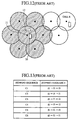
- a septuplet of radio cells 12 constitute one area as indicated by hatching in Fig. 12.
- the frequencies that are assigned to each of such areas repeat in a cyclic order; that is, the areas are common in the frequencies assigned thereto.
- Each area made up of seven radio cells will hereinafter be referred to as a repetition area. Further the number of radio cells forming the repetition area will hereinafter be referred to as a repetition cell number. In the prior art example of Fig. 12 the repetition cell number is seven.
- the radio cells forming the repetition area are each assigned a plurality of frequencies, which will hereinafter be referred to as a frequency group. And the radio cells making up the repetition area are each assigned seven different frequency groups.
- the base station 11 has control over the mobile stations 10 belonging to its radio cell and allocates to each mobile station 10 a hopping sequence for frequency hopping use.
- the base station 11 specifies predetermined hopping sequences for all the mobile stations 10 placed under its control. Based on the hopping sequence specified by the base station 11, each mobile station 10 performs frequency hopping.
- the mobile station M1 is assigned the hopping sequence c1, the mobile station m2 the hopping sequence c2, the mobile station m3 the hopping sequence m3, the mobile station M4 the hopping sequence c4, the mobile station m5 the hopping sequence c5 and the mobile station m6 the hopping sequence c6.
- the mobile stations M1 to m6 perform frequency hopping with fixed hopping periods based on the hopping sequences c1 to c6 respectively assigned to them.
- the frequencies f1, f2 and f3 will hereinafter called first, second and third frequencies in this order.
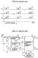
- Fig. 14 a description will be made of how frequency hopping takes place, for example, in the mobile stations M1 to m3 in the cell A.
- the abscissa represents time.
- the mobile station M1 uses the frequencies f1, f2 and f3 when it outputs bursts B1, B2 and B3, respectively.
- the mobile station m2 uses the frequencies f2, f3 and f1 when it outputs bursts B1, B2 and B3, respectively.
- the mobile station m3 uses the frequencies f3, f1 and f2 when it outputs bursts B1, B2 and B3, respectively.
- the bursts B1 to B3 mentioned herein are pulse-like waves or waveforms created by dividing original data such as speech and adding a header or the like to each divided piece of data.
- the hopping sequences c1 to c3 assigned thereto, respectively the mobile stations M1 to m3 in the cell A will not he assigned the same frequency at the same timing.
- the mobile stations M4 to m6 in the cell B will not be assigned the same frequency at the same timing.
- Fig. 15 depicts in block form the mobile station 10 that forms the conventional mobile communication system. With reference to Fig. 15, the configuration of the conventional mobile station 10 will be described.
- reference numeral 20 denotes an antenna.
- Reference numeral 21 denotes a transmitting part, which is connected via a switch 22 to the antenna 20.
- Reference numeral 23 denotes a receiving part, which is also connected via the switch 22 to the antenna 20.
- Reference numeral 24 denotes a transmission/received data processing part, which is connected to the transmitting part 21 and the receiving part 23.
- Reference numeral 25 denotes a synthesizer part, which is connected to the transmitting part 21, the receiving part 23 and the transmission/received data processing part 24.
- Reference numeral 26 denotes a control part, which is connected to the transmission/received data processing part 24 and the synthesizer part 25.
- Reference numeral 24i denotes transmission data, which is input into the transmission/received data processing part 24.
- Reference numeral 24t denotes transmission burst data, which is provided from the transmission/received data processing part 24 to the transmitting part 21.
- Reference numeral 21t denotes a transmission signal, which is output from the transmitting part 21.
- Reference numeral 23r denotes a received signal, which is input into the receiving part 23.
- Reference numeral 24r denotes received burst data, which is provided from the receiving part 23 to the transmission/received data processing part 24.
- Reference numeral 24o denotes received data, which is output from the transmission/received data processing part 24.
- Reference numeral 25t denotes transmission frequency data, which is provided from the synthesizer part 25 to the transmitting part 21.
- Reference numeral 25r denotes receive frequency data, which is provided from the synthesizer part 25 to the receiving part 23.
- Reference numeral 26r denotes hopping sequence data, which is provided from the transmission/received data processing part 24 to the control part 26.
- the transmission/received data processing part 24 instructs the control part 26 to perform frequency hopping based on the hopping sequence data 26r.
- Reference numeral 26t denotes first switching data, which is provided from the control part 26 and fed into the synthesizer part 25.
- the synthesizer part 25 operates on the first switching data 26t, performing frequency hopping.
- Reference numeral 24g denotes a timing signal, which is provided from the transmission/received data processing part 24 and fed into the synthesizer part 25.
- the timing signal 24g is output from the transmission/received data processing part 24 based on the received burst data 24r.
- the mobile station 10 receives signals sent from the base station 11 by the antenna 20.
- the received signal 23r is applied from the antenna 20 to the receiving part 23 via the switch 22.
- the receiving part 23 demodulates it and outputs the received burst data 24r, which is fed into the transmission/received data processing part 24.
- the transmission/received data processing part 24 decodes the received burst data and outputs the received data 24o. Further, the transmission/received data processing part 24 extracts the hopping sequence data 26r from the received burst data 24r. The transmission/received data processing part 24 applies the timing signal 24g to the synthesizer 25. Additionally, the transmission/received data processing part 24 is supplied with the transmission data 24i and generates therefrom the transmission burst data 24t, which is fed into the transmitting part 21. The hopping sequence data 26r output from the transmission/received data processing part 24 is input into the control part 26.
- the control part 26 determines the frequency desired to hop. And the control part 26 uses the first switching data 26t to indicate the thus determined hopping frequency to the synthesizer part 25.
- the synthesizer part 25 further receives the timing signal 24g from the transmission/received data processing part 24, and determines the frequency to hop and its timing.
- the synthesizer part 25 Based on the first switching data 26t fed thereinto, the synthesizer part 25 provides the transmission frequency data 25t or received frequency data 25r to the transmitting part 21 or receiving part 23 so that the frequency to be used by the mobile communication system equipped with the synthesizer part 25 is switched, for example, from a first to a second frequency.
- the synthesizer part 25 When the synthesizer part 25 indicates a predetermined frequency to the transmitting part 21, the former provides the transmission frequency data 25t to the latter. When the synthesizer part 25 indicates a predetermined frequency to the receiving part 23, the former provides the received frequency data 25t to the latter.
- the transmission burst data 24t provided from the transmission/received data processing part 24 is input into the transmitting part 21. Supplied with the transmission burst data 24t, the transmitting part 21 modulates it based on the transmission frequency data 25t and outputs the transmission signal 21t.
- the transmission signal 21t provided from the transmitting part 21 is sent to the base station 11 via the switch 22 and the antenna 20.
- a secondary object of the present invention is to provide a mobile communication system which performs frequency hopping only at frequencies of high receiving level, ensuring excellent speech quality.
- a mobile communication system which comprises a base station and a mobile station that communicates therewith while performing frequency hopping based on a predetermined hopping sequence and in which, based on the received power of a signal received from the base station at a first frequency in the hopping sequence, the mobile station switches the first frequency to a second one next thereto in the hopping sequence and keeps on communicating with the base station at the second frequency.
- This system configuration permits high-quality, high-reliability communications between the base and the mobile station.
- a mobile communication system in which, when the received power of a signal received by a mobile station from a base station at a first frequency in a hopping sequence is above a predetermined power level, the mobile station communicates with the base station at the first frequency, whereas when the received power is below the predetermined power level the mobile station switches the first frequency to a second one next thereto in the hopping sequence and continues to communicate with the base station at the second frequency.
- the power level of the mobile station is low, frequency hopping is carried out so that the frequency for use in the mobile station is switched to facilitate communications with the base station at a higher power level.
- a mobile communication system which comprises a base station and a mobile station that communicates therewith while performing frequency hopping based on a predetermined hopping sequence and in which the mobile station outputs information based on the received power of a signal received from the base station at a first frequency in the hopping sequence and, based on the information received from the mobile station, the base station switches the first frequency to a second one next thereto in the hopping sequence and keeps on communicating with the mobile station at the second frequency.
- This system configuration also permits high-quality, high-reliability communications between the base and the mobile station.
- a mobile communication system which comprises a mobile station and a base station that communicates therewith while performing frequency hopping based on a predetermined hopping sequence and in which, based on the received power of a signal received from the mobile station at a first frequency in the hopping sequence, the base station switches the first frequency to a second one next thereto in the hopping sequence and keeps on communicating with the mobile station at the second frequency.
- This system configuration also permits high-quality, high-reliability communications between the base and the mobile station.
- a mobile communication system which, when the received power of a signal received by a base station from a mobile station at a first frequency in a hopping sequence is above a predetermined power level, the base station communicates with the mobile station at the first frequency, whereas when the received power is below the predetermined power level the base station switches the first frequency to a second one next thereto in the hopping sequence and continues to communicate with the mobile station at the second frequency.
- the base station when the received power level of the mobile station is low, frequency hopping is carried out so that the frequency for use in the mobile station is switched to facilitate communications at a higher power level.
- This system configuration also provides high-quality, high-reliability communications between the base and the mobile station.
- a mobile communication system which comprises a mobile station and a base station that communicates therewith while performing frequency hopping based on a predetermined hopping sequence and in which the base station outputs information based on the received power of a signal received from the mobile station at a first frequency in the hopping sequence and, based on the information received from the base station, the mobile station switches the first frequency to a second one next thereto in the hopping sequence and continues to communicate with the base station at the second frequency.
- This system configuration also permits high-quality, high-reliability communications between the base and the mobile station.
- a mobile communication system which, based on the received power of an interference received together with a received signal from the mobile station at a first frequency, switches the first frequency to a second one next thereto in the hopping sequence and thereafter establishes communications between a base and a mobile station at the second frequency.
- This system configuration also provides high-quality, high-reliability communications between the base and mobile station.
- a mobile communication system in which, when the received power of an interference received together with a received signal of a first frequency in a hopping sequence is below a predetermined power level, a base and a mobile station communicate with each other at the first frequency, whereas when the received power of the interference is above the predetermined power level the first frequency is switched to a second frequency next thereto in the hopping sequence for subsequent communications between the base and the mobile station.
- frequency hopping is carried out so that the frequency for use in the mobile station is switched to raise the received power level of the desired received signal and reduce that of the interference.
- This system configuration also provides high-quality, high-reliability communications between the base and the mobile station.
- a mobile communication system which comprises a base station and a mobile station that communicates therewith while performing frequency hopping based on a predetermined hopping sequence and in which, based on the received power of an interference received together with a received signal from the base station at a first frequency in the hopping sequence, the mobile station switches the first frequency to a second one next thereto in the hopping sequence and thereafter establishes communications with the base station at the second frequency.
- This system configuration also permits high-quality, high-reliability communications between the base and the mobile station.
- a mobile communication system in which, when the received power of an interference received together with a received signal from a base station at a first frequency in a hopping sequence is below a predetermined power level, a mobile station communicates with the base station at the first frequency, whereas when the received power of the interference wave above the predetermined power level the mobile station switches the first frequency to a second one next thereto in the hopping sequence and thereafter establishes communications with the base station at the second frequency.
- frequency hopping is carried out so that the frequency for use in the mobile station is switched to reduce the received power level of the interference.
- This system configuration also provides high-quality, high-reliability communications between the base and the mobile station.
- a mobile communication system which comprises a base station and a mobile station that communicates therewith while performing frequency hopping based on a predetermined hopping sequence and in which the mobile station outputs information based on the received power of an interference received together with a received signal from the base station at a first frequency in the hopping sequence and, based on the information received from the mobile station, the base station switches the first frequency to a second one next thereto in the hopping sequence and keeps on communicating with the mobile station at the second frequency.
- This system configuration also permits high-quality, high-reliability communications between the base and the mobile station.
- a mobile communication system which comprises a mobile station and a base station that communicates therewith while performing frequency hopping based on a predetermined hopping sequence and in which, based on the received power of an interference received together with a received signal from the mobile station at a first frequency in the hopping sequence, the base station switches the first frequency to a second one next thereto in the hopping sequence and keeps on communicating with the mobile station at the second frequency.
- This system configuration also permits high-quality, high-reliability communications between the base and the mobile station.
- a mobile communication system in which, when the received power of an interference received together with a received signal from a mobile station at a first frequency in a hopping sequence is below a predetermined power level, a base station communicates with the mobile station at the first frequency, whereas when the received power of the interference is above the predetermined power level the base station switches the first frequency to a second one next thereto in the hopping sequence and thereafter establishes communications with the mobile station at the second frequency.
- frequency hopping is carried out so that the frequency for use in the base station is switched to reduce the received power level of the interference.
- This system configuration also provides high-quality, high-reliability communications between the base and the mobile station.
- a mobile communication system which comprises a mobile station and a base station that communicates therewith while performing frequency hopping based on a predetermined hopping sequence and in which the base station outputs information based on the received power of an interference received together with a received signal from the mobile station at a first frequency in the hopping sequence and based on the information received from the base station, the mobile station switches the first frequency to a second one next thereto in the hopping sequence and keeps on communicating with the base station at the second frequency.
- This system configuration also permits high-quality, high-reliability communications between the base and the mobile station.
- a mobile communication system in which a mobile or base station selects those of a plurality of frequencies in a hopping sequence at which received signals of the selected frequencies will satisfy predetermined requirements of received power, and forms a hopping sequence unique to the mobile or base station accordingly.
- this mobile communication system it is possible to perform frequency hopping based on the unique hopping sequence in which frequencies, at which the received power level is high, are arranged in a sequential order according to the hysteresis of the mobile or base station in the past--this permits relatively stable communications between the base and the mobile station.
- a mobile communication system in which a mobile or base station detects the received power of a received signal at every frequency in a hopping sequence for each cycle during which the mobile or base station performs frequency hopping to all the frequencies in the hopping sequence, then records in a recording part the frequency at which the received power was at a maximum, and creates an original hopping sequence based on plural frequencies recorded in the recording part.
- this mobile communication system it is possible to perform frequency hopping based on the unique hopping sequence in which frequencies, at which the received power level is high, are arranged in a sequential order according to the hysteresis of the mobile or base station in the past. This also permits relatively stable communications between the base and the mobile station.
- a mobile communication system in which a mobile or base station removes from its own unique hopping sequence that one of a plurality of frequencies at which a received signal will not satisfy predetermined requirements of received power. With this mobile communication system, that one of the frequencies in the hopping sequence which does not satisfy the predetermined requirements is replaced with a frequency that meets the requirements. This also permits relatively stable communications between the base and the mobile station.
- a mobile communication system which comprises a base station, a first mobile station that communicates therewith while performing frequency hopping based on a first hopping sequence, and a second mobile station that communicates with the base station while performing frequency hopping based on a second hopping sequence and in which, when the first mobile station which communicates with the base station at a first frequency in the first hopping sequence, continues to communicate with the base station at the first frequency based on the received power of a signal received from the base station at the first frequency, the second mobile station communicates with the base station while performing frequency hopping based on the second hopping sequence composed of a plurality of frequencies except the first frequency.
- a mobile communication system in which, when a first mobile station communicates with a base station at a first frequency in a first hopping sequence and the received power of a received signal at the first frequency from the base station is above a predetermined power level, the first mobile station keeps on communicating with the base station at the first frequency.
- This mobile communication system permits high-quality, high-reliability communications.
- a mobile communication system in which a first mobile station communicates with a base station at a first frequency in a first hopping sequence and when the received power of a received signal at the first frequency from the base station is above a predetermined power level, the first mobile station keeps on communicating with the base station at the first frequency, and in which a second mobile station communicates with the base station at a second frequency in a second hopping sequence and when the received power of a received signal at the second frequency from the base station is below a predetermined power level, the second mobile station communicates with the base station while performing frequency hopping based on the second hopping sequence composed of a plurality of frequencies except the first frequency.
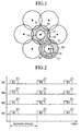
- Fig. 1 conceptually illustrates the mobile communication system according to Embodiment 1 of the present invention.
- Reference numeral 30 denotes a first coverage area, and 31 a second coverage area.
- Each radio cell 12 is composed of the first and second coverage areas 30 and 31.
- the parts identical with or corresponding to those in the mobile station of the prior art example depicted in Fig. 12 will be identified by the same reference numerals and no description will be given thereof; only parts different from those in Fig. 12 will be described.
- Fig. 1 there is depicted an arrangement of the radio cells 12.
- Each of the cells 12 indicates the coverage area defined about the corresponding base station 11 with which the mobile station 10 exchanges data.
- Fig. 1 when the mobile station 10 is in the second coverage area 31 where the receiving level is high (in the case of the cell B), no frequency hopping is performed between the mobile station 10 and the base station 11.
- the mobile station 10 is in the first coverage area 30 where the receiving level is low (in the case of the cell A)
- frequency hopping is performed between the mobile station 10 and the base station 11. That is, in the mobile communication system according to Embodiment 1, it is determined, based on the receiving level of a signal received by the mobile station 10 or the base station 11 at a certain frequency , whether or not the mobile station 10 performs frequency hopping with respect to the base station 10.
- the receiving level herein mentioned is the power level concerning the received power of the received signal.
- Fig. 2 firstly seven hopping sequences z1 to z7 that are provided for the cell A will be described, for example, in the case where cell A is assigned frequencies F1, F2, F3 and F4. Let it be assumed that first through fourth mobile stations M1 to M4 are present in the cell A.
- the abscissa represents time.
- the mobile stations M1, M2, M3 and M4 are assigned the hopping sequences z1, z2, z3 and z4, respectively.
- the frequency that the mobile station M1 uses in the hopping period concerning the next burst B2 is switched to the frequency F2.
- the mobile station M3 is switched from the frequency F3 to F4 and the mobile station M4 from the frequency F4 to F2.
- the base station 11 assigns the mobile stations M2 to M4 the new hopping sequences z5 to z7 that do not contain the frequency F1 to be used by the mobile station M1, and causes them to perform frequency hopping.
- the mobile station M2 is assigned the hopping sequence z5, the mobile station M3 the hopping sequence z6 and the mobile station M4 the hopping sequence z7.
- the mobile stations M2 to M4 perform frequency hopping based on the hopping sequences z5 to z7 assigned to them, respectively, unless the receiving level in the mobile station M1 falls short of a predetermined level.
- the mobile stations M2 t M4 are present in the first, coverage area 30 remote from the base station 11.
- the hopping sequences z1 to z7 are prepared so that the same frequency will not be used in the mobile stations M1 to M4 at the same time.
- the received level of a signal transmitted between the mobile stations M1 to M4 and the base station 11 is strongly affected by geographical features. On account of this, the first and second coverage areas 30 and 31, which are defined by the received level of a signal do not always become concentric as depicted in Fig. 1.
- the transmission power of a signal that is output from each of the mobile stations M1 to M4 and the base station 11 may be reduced to such an extent as not to involve frequency hopping.
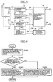
- FIG. 3 illustrates in block form the mobile station 10.
- the constituents identical with those in the conventional mobile station 10 depicted in Fig. 15 are identified by the same reference numerals and no description will be given of them.
- reference numeral 40 denotes a level detecting part, which is connected to the receiving part 23 and the control part 26.
- Reference numeral 40r denotes level information about a received signal of a frequency received from the base station 11, which information is provided from the receiving part 23 to the level detecting part 40.
- Reference numeral 40t denotes level detected data, which is provided from the level detecting part 40 to the control part 26.
- the level detecting part 40 detects the received level of the received signal based on the level information 40r input thereinto. And the level detecting part 40 outputs the level detected data 40t based on the detected received level.
- the level information 40r is input into the level detecting part 40 via the antenna 20, the switch 22 and the receiving part 23. Based on the level information 40r input thereinto, the level detecting part 40 detects the received level of the signal received by the mobile station 10 or the base station 11. Then, the level detecting part 40 supplies the control part 26 with the level detected data 40t based on the input level information 40r.
- the control part 26 Based on the level detected data 40t input thereinto, the control part 26 makes a check to see if the detected level exceeds a predetermined threshold value. When the detected level is above the predetermined threshold value, no frequency hopping will take place between the mobile station 10 and the base station 11. When the detected level is below the predetermined threshold value, frequency hopping is performed between the mobile station 10 and the base station 11. In the latter case, the synthesizer part 25 switches, for example, the first frequency to the second one, depending on the first switching data 26t that is provided from the control part 26.
- the timing for the frequency switching by the synthesizer part 25 is determined by the timing signal 24g that is provided from the transmission/receive data processing part 24.
- the first switching data 26t that is provided from the control part 26 is determined based on the hopping sequence data 26r also available from the transmission/receive data processing part 24. Further, it is considered that the frequency hopping is carried out when the received level of the received signal is below the predetermined threshold value as well as when the former does not exceed the latter. While in Embodiment 1 the mobile station performs the frequency switching after detecting the received level, the base station may also perform the detection of the received level and the frequency switching in this order. It is also possible that the mobile station detects the received level and indicates the detection result to the base station, causing it to perform the frequency switching. Alternatively, the base station may detect the received level first and then indicate the detection result to the mobile station, causing it to perform the frequency switching.
- FIG. 4 is a flowchart depicting the operation of the control part 26 of the mobile station 10 forming the mobile communication system according to Embodiment 1.
- step S1001 the control part 26 receives the level detected data 40t and the hopping sequence data 26r. Step S1001 is followed by step S1002.
- step S1002 based on the level detected data 40t input thereinto, the control part 26 makes a check to determine if the level of the received wave exceeds a predetermined threshold value. When the level of the received wave is above the predetermined threshold value, the procedure goes to step S1003. When the level of the received wave is below the predetermined threshold value, the procedure proceeds to step S1004.
- step S1003 the control part 26 determines that no frequency hopping be carried out, and supplies the synthesizer part 25 with the first switching data indicating the frequency being used at that time.
- the control part 26 terminates a sequence of processing steps with step S1003.
- step S1004 the control part 26 determines that frequency hopping be carried out, then determines the frequency to be switched by the frequency hopping based on the hopping sequence data 26r received from the send/receive data processing part 24, and supplies the synthesizer part 25 with the first switching data 26t indicating the thus determined frequency.
- the control part 16 terminates a sequence of processing steps with step S1004.
- the mobile communication system of this embodiment determines whether or not to perform frequency hopping between the mobile station 10 and the base station 11, based on the receiving level of the received wave that is a signal of a frequency received by the mobile station 10 or the base station 11 from the latter or the former.
- the receiving level of the received wave is low, frequency hopping is carried out, whereas when the receiving level is high, no frequency hopping takes place. Accordingly, frequency hopping is performed for the mobile station 10 of a low receiving level to switch the frequency being used therein to facilitate communications at a higher receiving level.
- no frequency hopping is carried out and the mobile station 10 keeps on high-quality, high-reliability communications with the base station 11.
- the mobile communication system permits reduction of the sending power of a signal that is sent from the mobile station 10 or the base station 11 when the receiving level of the received wave is high. Hence, it is possible to suppress interference between the above-mentioned send signal and a signal that is output from a mobile or base station in the neighboring repetition area which uses the same frequency as that in the above.
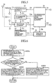
- FIG. 5 illustrates in block form the mobile station 10 that forms the mobile communication system according to Embodiment 2.
- the mobile communication system of this embodiment observes the receiving level of an interference wave that is a received signal of a frequency different from that of the signal sent from the base station 11, and performs frequency hopping based on the result of observation.
- reference numeral 41 denotes an interference wave level detecting part, which is connected to the receiving part 23 and the control part 26.
- Reference numeral 41r denotes interference wave level information, which is provided from the receiving part 23 to the interference wave level detecting part 41.
- Reference numeral 41t denotes interference wave level detected data, which is provided from the interference wave level detecting part 41 to the control part 26.
- the interference wave level detecting part 41 detects the interference wave receiving level based on the interference wave level information 41r input there into. Then, the interference wave level detecting part 42 supplies the control part 26 with the interference wave level detected data 41t based on the detected receiving level.
- the interference wave level information 41r is input into the interference wave level detecting part 41 via the antenna 20, the switch 22 and the receiving part 23. Based on the interference wave level information 41r input thereinto, the interference wave level detecting part 41 detects the receiving level of the interference wave received by the mobile station 10 or the base station 11. Then the interference wave level detecting part 41 provides to the control part 26 the interference wave level detected data 41r based on the input interference wave level information 41r.
- the control part 26 Based on the interference wave level detected data 41t input thereinto, the control part 26 makes a check to determine if the detected interference wave level exceeds a predetermined threshold value. When the detected interference wave level does not exceed the predetermined threshold value, no frequency hopping takes place between the mobile station 10 and the base station 11. When the detected interference wave level exceeds the predetermined threshold value, frequency hopping is carried out between the mobile station 10 and the base station 11. When the frequency hopping is performed, the synthesizer part 25 switches, for example, the first frequency to the second one, based on the first switching data 26t provided from the control part 26.
- the timing for the frequency switching by the synthesizer part 25 is determined by the timing signal 24g that is provided from the send/receive data processing part 24.
- the first switching data 26t that is provided from the control part 26 is determined using the hopping sequence data 26r also available from the send/receive data processing part 24.
- the frequency hopping between the mobile station 10 and the base station 11 may also be carried out through the combined use of the receiving level of the received wave and the interference wave receiving level.
- the frequency hopping takes place in the case where the receiving level of the received wave and the interference wave receiving level are both low, where the receiving level of the received wave is low but the interference wave receiving level is high, or where the receiving level of the received wave and the interference wave receiving level are both high. It is also considered that the frequency hopping is carried out when the interference wave receiving level is above the predetermined threshold value as well as when the former is equal to the latter. While in Embodiment 2 the mobile station performs the frequency switching after detecting the receiving level, the base station may also perform the detection of the interference wave receiving level and the frequency switching in this order. It is also possible that the mobile station detects the interference wave receiving level and indicates the detection result to the base station, causing it to perform the frequency switching. Alternatively, the base station may detect the interference wave receiving level first and then indicate the detection result to the mobile station, causing it to perform the frequency switching.
- FIG. 6 is a flowchart depicting the operation of the control part 26 of the mobile station 10 forming the mobile communication system according to Embodiment 2.
- step S2001 the control part 26 receives the interference wave level detected data 41t and the hopping sequence data 26r. Step S2001 is followed by step S2002.
- step S2002 based on the interference wave level detected data 41t input thereinto, the control part 26 makes a check to determine if the level of the received wave exceeds a predetermined threshold value. When the interference wave level is below the predetermined threshold value, the procedure proceeds to step S2004. When interference wave level is above the predetermined threshold value, the procedure goes to step S2003.
- step S2003 the control part 26 determines that no frequency hopping be carried out, and supplies the synthesizer part 25 with the first switching data indicating the frequency being used at that time. A sequence of operations by the control part 26 is completed with step S2003.
- step S2004 the control part 26 determines that the frequency hopping be carried out, then determines the frequency to be switched by the frequency hopping based on the hopping sequence data 26r received from the send/receive data processing part 24, and supplies the synthesizer part 25 with the first switching data 26t indicating the thus determined frequency.
- a sequence of operations by the control part 26 terminates with step S2004.
- the mobile communication system of this embodiment determines whether or not to perform frequency hopping between the mobile station 10 and the base station 11, based on the receiving level of the interference wave that is a signal of a frequency different from that of a signal received by the mobile station 10 or the base station 11 from the latter or the former.
- the interference wave receiving level low, frequency hopping is carried out, whereas when the interference wave receiving level is high, no frequency hopping takes place. Accordingly, frequency hopping is performed for the mobile station 10 of a high interference wave receiving level to switch the frequency being used therein to facilitate communications at a higher receiving level.
- frequency hopping is carried out to switch the frequency being used by the mobile station 10, enabling it to communicate with the base station 11 at a higher receiving level.
- this system offers an excellent transmission quality with a low interference wave receiving level and an enhanced received signal vs. same frequency interference power ratio, ensuring high-quality, high-reliability communications between the mobile station 10 and the base station 11.
- frequency hopping is carried out based on the interference wave receiving level, switching the frequency at which the mobile station 10 and the base station 11 communicate with each other. This breaks up the influence of interference power by an arbitrary frequency and averages the interference power that each mobile station 10 suffers.
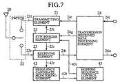
- Embodiment 3 depicted in Fig. 7 is directed to a mobile communication system that generates a hopping sequence and performs frequency hopping based on the hopping sequence.
- Fig. 7 illustrates in block form the mobile station 10 that has a hopping sequence according to Embodiment 3.
- reference numeral 42 denotes a frequency candidate monitoring part, which is connected to the receiving part 23 and a hopping sequence control part 43.
- the hopping sequence control part 43 is connected to the frequency candidate monitoring part 42 and the synthesizer part 25.
- Reference numeral 42r denotes frequency candidate information, which is input into the frequency candidate monitoring part 42 via the receiving part 23.
- the frequency candidate information 42r is information that is used to indicate one of given frequencies to each radio cell.
- Reference numeral 42t denotes hopping sequence candidate data, which is provided from the frequency candidate monitoring part 42 to the hopping sequence control part 43.
- the frequency candidate monitoring part 42 makes a check to if the frequency based on the frequency candidate information 42r satisfies given requirements. Based on the result of this check, the frequency candidate monitoring part 42 outputs the hopping sequence candidate data 42t.
- Reference numeral 43t denotes second switching data, which is provided from the hopping sequence control part 43 to the synthesizer part 25. Based on the second switching data 43t input thereinto, the synthesizer part 25 switches, for example, the first frequency to the second one.
- the second switching data 43t is output from the hopping sequence control part 43 based on the hopping sequence candidate data 42t input there into.
- the frequency candidate information 42r is input into the frequency candidate monitoring part 42 via the antenna 20, the switch 22 and the receiving part 23. Based on the frequency candidate information 42r input thereinto, the frequency candidate monitoring part 42 determines the frequency to be switched at the timing at which the frequency hopping is carried out next, and provides to the hopping sequence control part 43 the hopping sequence candidate data 42t indicative of the determined frequency.
- the hopping sequence control part 43 Based on the hopping sequence candidate data 42t input thereinto, the hopping sequence control part 43 provides to the synthesizer part 25 the second switching data 43t that designates the same frequency as that specified by the hopping sequence candidate data 42t. Based on the second switching data 43t provided from the hopping sequence control part 43 and the timing signal 24g from the send/receive data processing part 24, the synthesizer part 25 provides to the transmitting part 21 the transmitting frequency data 25t for switching the frequency to be output therefrom, or provides the received frequency data 25r to the receiving part 23.
- the hopping sequence control part 43 sequentially records in a memory or similar recording part all pieces of the hopping sequence candidate data 42t input thereinto.
- the hopping sequence control part 43 independently generates a hopping sequence from the plurality of recorded pieces of hopping sequence candidate data 42t and holds the hopping sequence.
- the hopping sequence control part 43 uses its generated hopping sequence to determine the frequency to be switched at the timing of the next frequency hopping, and indicates the determined frequency to the synthesizer part 25 by sending thereto the second switching data 43t.
- the mobile communication system performs the frequency hopping based on the hopping sequence generated by the hopping sequence control part 43.
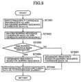
- Fig. 8 is a flowchart showing the operations of the frequency candidate monitoring part 42 and the hopping sequence control part 43 forming the mobile communication system according to Embodiment 3.
- step S3001 the frequency candidate monitoring part 42 receives the frequency candidate information 42r from the receiving part 23.
- the frequency candidate monitoring part 42 determines from the frequency candidate information 42r input thereinto the frequency to be switched at the timing of the next frequency hopping, and provides to the hopping sequence control part 43 the hopping sequence candidate data 42t indicative of the determined frequency.
- Step S3001 is followed by step S3002.
- step S3002 the hopping sequence control part 43 records the hopping sequence candidate data 42t input thereinto.
- the hopping sequence control part 43 When the number of recorded hopping sequence candidate data 42t reaches a predetermined value, the hopping sequence control part 43 generates a hopping sequence from the plurality of recorded hopping sequence candidate data 42t.
- Step S3002 is followed by step S3003.
- step S3003 the hopping sequence control part 43 makes a check to determine if a hopping sequence has been completely generated from the predetermined number of recorded hopping sequence candidate data 42t. If so, the procedure proceeds to step S3004, and if not, then the procedure goes to step S3005.
- step S3004 the hopping sequence control part 43 determines from its generated hopping sequence the frequency to be switched at the timing of the next frequency hopping. Step S3004 is followed by step S3006.
- step S3005 the hopping sequence control part 43 determines, from the hopping sequence candidate data 42t input thereinto, the frequency to be switched at the timing of the next frequency hopping. Step S3005 is followed by step S3006.
- step S3006 the hopping sequence control part 43 indicates its determined frequency to the synthesizer 24 by sending thereto the second switching data 43t. A sequence of operations ends with step S3006.
- Fig. 9 is a flowchart for explaining the process in step S3001 in the Fig. 8 flowchart by which the frequency candidate monitoring part 42 determines the frequency to be switched by frequency hopping.
- step S4001 is followed by step S4002.
- step S4002 the frequency candidate monitoring part 42 detects the receiving level Ri of the frequency number i, and compares the detected receiving level Ri with a preset threshold value Ra of the receiving level. When the receiving level Ri exceeds the threshold value Ra, the procedure proceeds to step S4005. When the receiving level Ri falls short of the threshold value Ra, the procedure goes to step S4003. In step S4003 the frequency candidate monitoring part 42 increments the frequency number i. Step S4003 is followed by step S4004.
- the frequency candidate monitoring part 42 makes a check to determine if the incremented frequency number i exceeds the frequency number N that is a given number of frequencies. When the frequency number i exceeds the frequency number N, the procedure returns to step S4001. When the frequency number i does not exceed the frequency number N, the procedure goes back to step S4002.
- step S4005 the frequency candidate monitoring part 42 determines the frequency that is switched at the timing of the next frequency hopping, and provides to the hopping sequence control part 43 the hopping sequence candidate data 42t indicative of the determined frequency. A series of operations by the frequency candidate monitoring part 42 ends with step S4005.
- the frequency to be switched by frequency hopping is determined based on the frequency receiving level
- the frequency to be switched may also be determined using the interference wave receiving level instead of using the frequency receiving level.
- the mobile communication system uses, for frequency hopping, a hopping sequence generated through utilization of the hysteresis of each mobile station in the past.
- a mobile station of a high frequency of use in a predetermined coverage area need not perform frequency hopping based on a predetermined hopping sequence in which there are arranged frequencies whose receiving levels are not always high in the coverage area; but instead such a mobile station is allowed to perform frequency hopping based on its own hopping sequence in which there are arranged frequencies of high receiving levels in the coverage area. This provides relatively stable communications between the mobile station and the base station.
- Fig. 10 is a flowchart explaining the operation by which the frequency candidate monitoring part 42 determines the frequency to be switched by frequency hopping in a manner different from that described above in respect of step S3001 in the Fig. 8 flowchart.
- Fig. 8 is a flowchart for explaining the operation of the frequency candidate monitoring part 42 for determining the frequency to be switched by frequency hopping in step S3001 in the Fig. 8 flowchart.
- step S5001 is followed by step S5002.
- step S5002 the frequency candidate monitoring part 42 records, as the maximum receiving level Rmax, the receiving level Ri of a predetermined frequency assigned the frequency number i.
- step S5002 is followed by step S5003.
- step S5003 the frequency candidate monitoring part 42 increments the frequency number i. Step S5003 is followed by step S5004.
- step S5004 the frequency candidate monitoring part 42 makes a check to determine if the incremented frequency number i exceeds the frequency number N. When the frequency number i exceeds the frequency number N, the procedure goes to step S5006. When the frequency number i does not exceed the frequency number N, the procedure goes to step S5005.
- step S5005 the frequency candidate monitoring part 42 compares the receiving level Ri concerning the predetermined frequency of the incremented frequency number i with the maximum receiving level Rmax recorded based on the results of comparison made so far.
- the procedure goes back to step S5002.
- the receiving level Ri does not exceed the maximum receiving level Rmax, the procedure returns to step S5003.
- step S5006 the frequency candidate monitoring part 42 determines the frequency that is switched at the timing of the next frequency hopping, and provides to the hopping sequence control part 43 the hopping sequence candidate data 42t indicative of the determined frequency. A series of operations by the frequency candidate monitoring part 42 ends with step S5006.
- the frequency to be switched by frequency hopping is determined based on the frequency receiving level
- the frequency to be switched may also be determined using the interference wave receiving level instead of using the frequency receiving level.
- the mobile communication system uses, for frequency hopping, a hopping sequence generated through utilization of the hysteresis of each mobile station in the past.
- a mobile station of a high frequency of use in a predetermined coverage area need not perform frequency hopping based on a predetermined hopping sequence in which there are arranged frequencies whose receiving levels are not always high in the coverage area; but instead such a mobile station is allowed to perform frequency hopping based on its own hopping sequence in which there are arranged frequencies of high receiving levels in the coverage area. This provides relatively stable communications between the mobile station and the base station.
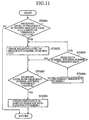
- Fig. 11 is a flowchart for explaining an operation by which the hopping sequence generated by the method described above in respect of Embodiment 3 or 4 is updated with levels or interference levels that are detected when frequency hopping is carried out based on the hopping sequence.
- Fig. 11 is a flowchart explanatory of the hopping sequence updating process corresponding to step S3001 in the Fig. 8 flowchart.
- step S6001 in Fig. 11 the frequency candidate monitoring part 42 makes a check to see if the receiving level of a frequency concerned in the hopping sequence of the mobile station 10 falls short of the preset threshold value Ra.
- the procedure goes to step S6002.
- the receiving level does not fall short of the threshold value Ra, the procedure ends.
- step S6002 the procedure goes to step S6003.
- step S6003 the frequency candidate monitoring part 42 makes a check to see if the receiving level Ri concerning a frequency of a certain frequency number i exceeds the preset threshold value Ra.
- the procedure goes to step S6006.
- the receiving level does not exceed the threshold value Ra, the procedure goes to step S6004.
- step S6004 the frequency candidate monitoring part 42 increments the frequency number i. Upon completion of step S6004, the procedure goes to step S6005.
- step S6005 the frequency candidate monitoring part 42 makes a check to determine if the incremented frequency number i exceeds the frequency number N. When the frequency number i exceeds the frequency number N, the procedure goes back to step S6002. When the frequency number i does not exceed the frequency N, the procedure returns to step S6003.
- step S6006 the frequency candidate monitoring part 42 provides to the hopping sequence control part 43 the hopping sequence candidate data 42t indicative of the frequency of the frequency number i concerned. Based on the hopping sequence candidate data input thereinto, the hopping sequence control part 43 updates data concerning the corresponding frequency in the hopping sequence that the mobile station 10 uses. A sequence of hopping sequence updating operations terminates with step S6006.
- the frequency in the hopping sequence at which the predetermined receiving level is not reached is switched to a frequency which satisfies the requirement.
- a frequency at which the predetermined receiving level is not reached may be a frequency of the receiving level higher than any other observable frequencies.
- the frequency hopping is carried out based on the predetermined hopping sequence until the original hopping sequence is generated.
- the original hopping sequence may be updated upon each elimination of an element forming the hopping sequence.
- the predetermined hopping sequence is used from the time when one element of the original hopping sequence is removed therefrom to the time when the hopping sequence is updated with a new element.
- the original hopping sequence need not always be updated until a predetermined number of elements are eliminated therefrom.
- the hopping sequence with some elements removed therefrom is used intact until a predetermined number of elements are eliminated, and the predetermined hopping sequence is used from the time when the predetermined number of elements are eliminated to the time when the original hopping sequence is updated with a required number of new elements. It is possible to use different criteria for selecting arbitrary frequencies for forming the original hopping sequence and for eliminating therefrom arbitrary frequencies.
- the mobile communication system uses, for frequency hopping, a hopping sequence generated through utilization of the hysteresis of each mobile station in the past.
- a mobile station of a high frequency of use in a predetermined coverage area need not perform frequency hopping based on a predetermined hopping sequence in which there are arranged frequencies whose receiving levels are not always high in the coverage area; but instead such a mobile station is allowed to perform frequency hopping based on its own hopping sequence in which there are arranged frequencies of high receiving levels in the coverage area. This provides relatively stable communications between the mobile station and the base station.
- the mobile communication system uses, for frequency hopping, a hopping sequence generated through utilization of the hysteresis of each mobile station in the past, it is possible to obtain more actually usable channels than in the case of a fixed frequency assignment system in which predetermined hopping sequence is assigned to each frequency.
- the frequency in the original hopping sequence of this system at which the receiving level of the received wave is below the predetermined threshold value is replaced with that one of given frequencies at which the receiving level of the received wave exceeds the predetermined threshold value, by which the hopping sequence is updated. This ensures relatively stable, highly reliable communications between the mobile and the base station.
- the frequency in the original hopping sequence of this system at which the interference wave receiving level exceeds a predetermined threshold value is substituted for that one of given frequencies at which the interference wave receiving level falls short of the predetermined threshold value, by which the hopping sequence is updated. This ensures relatively stable, highly reliable communications between the mobile and the base station.
Applications Claiming Priority (3)
| Application Number | Priority Date | Filing Date | Title |
|---|---|---|---|
| JP155033/97 | 1997-06-12 | ||
| JP15503397A JP3478062B2 (ja) | 1997-06-12 | 1997-06-12 | 移動通信システム、移動局、及び基地局 |
| JP15503397 | 1997-06-12 |
Publications (3)
| Publication Number | Publication Date |
|---|---|
| EP0884858A2 true EP0884858A2 (fr) | 1998-12-16 |
| EP0884858A3 EP0884858A3 (fr) | 2003-02-19 |
| EP0884858B1 EP0884858B1 (fr) | 2005-03-09 |
Family
ID=15597213
Family Applications (1)
| Application Number | Title | Priority Date | Filing Date |
|---|---|---|---|
| EP19980110630 Expired - Lifetime EP0884858B1 (fr) | 1997-06-12 | 1998-06-10 | Système de communication mobile utilisant l'évasion de fréquence |
Country Status (4)
| Country | Link |
|---|---|
| US (1) | US6295310B1 (fr) |
| EP (1) | EP0884858B1 (fr) |
| JP (1) | JP3478062B2 (fr) |
| DE (1) | DE69829246T2 (fr) |
Cited By (8)
| Publication number | Priority date | Publication date | Assignee | Title |
|---|---|---|---|---|
| EP1130858A2 (fr) * | 2000-02-29 | 2001-09-05 | Texas Instruments Incorporated | Sélection dynamique des esclaves dans transmissions sans fil de méthode du saut de fréquence |
| EP1257098A2 (fr) * | 2001-05-12 | 2002-11-13 | Samsung Electronics Co., Ltd. | Méthode d'éviter des interférences mutuelles entre des réseaux de communications sans fils et dispositif correspondant |
| EP1655855A1 (fr) * | 2004-11-03 | 2006-05-10 | Topspeed Technology Corp. | Méthode pour système à saut de fréquence pour éviter des interférences |
| EP1734660A1 (fr) * | 2005-06-15 | 2006-12-20 | Matsushita Electric Industrial Co., Ltd. | Commande de puissance de transmission dans un système utilisant des sauts de fréquence |
| EP2234280A1 (fr) | 2009-03-25 | 2010-09-29 | Austriamicrosystems AG | Procédé de commutation de canal et dispositif de communication |
| EP2302976A1 (fr) * | 2008-07-15 | 2011-03-30 | Panasonic Corporation | Dispositif de commande, dispositif terminal et système de communication et son procédé de communication |
| CN101518114B (zh) * | 2006-09-20 | 2012-03-21 | 日本电气株式会社 | 蜂窝系统的载波分配方法、蜂窝系统、基站以及移动台站 |
| EP2395675A3 (fr) * | 2010-06-14 | 2014-09-10 | ELDAT GmbH | Dispositif et procédé destinés à la surveillance d'une porte |
Families Citing this family (16)
| Publication number | Priority date | Publication date | Assignee | Title |
|---|---|---|---|---|
| EP0955780A1 (fr) * | 1998-04-17 | 1999-11-10 | Alcatel | Système de radiocommunication, station de base et terminal d'abonné mobile, échangeant des signaux radios selon une séquence de sauts de fréquences |
| CN100350755C (zh) * | 1999-05-27 | 2007-11-21 | 因芬尼昂技术股份公司 | 移动无线系统的跳频方法 |
| US8041359B1 (en) * | 1999-08-02 | 2011-10-18 | Alcatel Lucent | Method for maintaining a communication link in wireless network groups |
| GB9918250D0 (en) * | 1999-08-04 | 1999-10-06 | Koninkl Philips Electronics Nv | Generating a cyclic sequence of frequencies |
| US6961363B1 (en) * | 1999-12-02 | 2005-11-01 | International Business Machines Corporation | Frequency look-ahead and link state history based scheduling in indoor wireless pico-cellular networks |
| US6430395B2 (en) * | 2000-04-07 | 2002-08-06 | Commil Ltd. | Wireless private branch exchange (WPBX) and communicating between mobile units and base stations |
| US7274760B2 (en) * | 2000-08-01 | 2007-09-25 | George Palaskas | Circuit and method for dynamically modifiable signal processor |
| US7027418B2 (en) | 2001-01-25 | 2006-04-11 | Bandspeed, Inc. | Approach for selecting communications channels based on performance |
| US7366223B1 (en) * | 2002-06-06 | 2008-04-29 | Arraycomm, Llc | Modifying hopping sequences in wireless networks |
| KR100654316B1 (ko) * | 2004-12-08 | 2006-12-08 | 한국과학기술원 | 직교 주파수 및 직교 부호 도약 다중화 통신 방식 |
| US7769456B2 (en) * | 2006-09-01 | 2010-08-03 | Cardiac Pacemakers, Inc. | Frequency-agile system for telemetry with implantable device |
| WO2008030471A2 (fr) * | 2006-09-07 | 2008-03-13 | Impinj, Inc. | Procédés et systèmes de lecteur rfid pour sortir rapidement d'un canal de fréquence en présence d'interférence rf |
| JP5200701B2 (ja) * | 2008-07-02 | 2013-06-05 | 富士通株式会社 | 基地局装置、周波数割当て方法、移動通信システム、及び通信装置 |
| US8849213B2 (en) * | 2009-01-21 | 2014-09-30 | Bandspeed, Inc. | Integrated circuit for signal analysis |
| US8447252B2 (en) * | 2009-01-21 | 2013-05-21 | Bandspeed, Inc. | Adaptive channel scanning for detection and classification of RF signals |
| US20140044150A1 (en) * | 2012-08-13 | 2014-02-13 | Redline Communications, Inc. | System and method for interference triggered frequency hopping |
Citations (4)
| Publication number | Priority date | Publication date | Assignee | Title |
|---|---|---|---|---|
| US4479215A (en) * | 1982-09-24 | 1984-10-23 | General Electric Company | Power-line carrier communications system with interference avoidance capability |
| DE3415032A1 (de) * | 1983-04-27 | 1984-11-08 | Siemens AG, 1000 Berlin und 8000 München | Verfahren zur stoerresistenten funkuebertragung |
| WO1996002979A2 (fr) * | 1994-07-15 | 1996-02-01 | Telefonaktiebolaget Lm Ericsson | Sauts de canaux dans un systeme mobile de telecommunications |
| US5541954A (en) * | 1993-11-24 | 1996-07-30 | Sanyo Electric Co., Ltd. | Frequency hopping communication method and apparatus changing a hopping frequency as a result of a counted number of errors |
Family Cites Families (4)
| Publication number | Priority date | Publication date | Assignee | Title |
|---|---|---|---|---|
| JPH05110499A (ja) | 1991-10-14 | 1993-04-30 | Nippon Telegr & Teleph Corp <Ntt> | 移動通信方式 |
| JP3210949B2 (ja) | 1993-05-24 | 2001-09-25 | 日本電信電話株式会社 | スペクトル拡散通信方法 |
| FI940705A (fi) * | 1993-09-14 | 1995-03-15 | Nokia Telecommunications Oy | Menetelmä tukiaseman radiokanavien valvomiseksi |
| FI943609A (fi) * | 1994-08-03 | 1996-02-04 | Nokia Telecommunications Oy | Menetelmä kanavan allokoimiseksi solukkoradiojärjestelmässä |
-
1997
- 1997-06-12 JP JP15503397A patent/JP3478062B2/ja not_active Expired - Lifetime
-
1998
- 1998-06-04 US US09/090,215 patent/US6295310B1/en not_active Expired - Fee Related
- 1998-06-10 EP EP19980110630 patent/EP0884858B1/fr not_active Expired - Lifetime
- 1998-06-10 DE DE1998629246 patent/DE69829246T2/de not_active Expired - Lifetime
Patent Citations (4)
| Publication number | Priority date | Publication date | Assignee | Title |
|---|---|---|---|---|
| US4479215A (en) * | 1982-09-24 | 1984-10-23 | General Electric Company | Power-line carrier communications system with interference avoidance capability |
| DE3415032A1 (de) * | 1983-04-27 | 1984-11-08 | Siemens AG, 1000 Berlin und 8000 München | Verfahren zur stoerresistenten funkuebertragung |
| US5541954A (en) * | 1993-11-24 | 1996-07-30 | Sanyo Electric Co., Ltd. | Frequency hopping communication method and apparatus changing a hopping frequency as a result of a counted number of errors |
| WO1996002979A2 (fr) * | 1994-07-15 | 1996-02-01 | Telefonaktiebolaget Lm Ericsson | Sauts de canaux dans un systeme mobile de telecommunications |
Cited By (14)
| Publication number | Priority date | Publication date | Assignee | Title |
|---|---|---|---|---|
| EP1130858A3 (fr) * | 2000-02-29 | 2003-04-23 | Texas Instruments Incorporated | Sélection dynamique des esclaves dans transmissions sans fil de méthode du saut de fréquence |
| US6965590B1 (en) | 2000-02-29 | 2005-11-15 | Texas Instruments Incorporated | Dynamic slave selection in frequency hopping wireless communications |
| EP1130858A2 (fr) * | 2000-02-29 | 2001-09-05 | Texas Instruments Incorporated | Sélection dynamique des esclaves dans transmissions sans fil de méthode du saut de fréquence |
| US7372866B2 (en) | 2001-05-12 | 2008-05-13 | Samsung Electronics Co., Ltd. | Wireless communication method for avoiding mutual interference between wireless communication systems, and apparatus thereof |
| EP1257098A2 (fr) * | 2001-05-12 | 2002-11-13 | Samsung Electronics Co., Ltd. | Méthode d'éviter des interférences mutuelles entre des réseaux de communications sans fils et dispositif correspondant |
| EP1257098A3 (fr) * | 2001-05-12 | 2003-10-15 | Samsung Electronics Co., Ltd. | Méthode d'éviter des interférences mutuelles entre des réseaux de communications sans fils et dispositif correspondant |
| EP1655855A1 (fr) * | 2004-11-03 | 2006-05-10 | Topspeed Technology Corp. | Méthode pour système à saut de fréquence pour éviter des interférences |
| EP1734660A1 (fr) * | 2005-06-15 | 2006-12-20 | Matsushita Electric Industrial Co., Ltd. | Commande de puissance de transmission dans un système utilisant des sauts de fréquence |
| CN101518114B (zh) * | 2006-09-20 | 2012-03-21 | 日本电气株式会社 | 蜂窝系统的载波分配方法、蜂窝系统、基站以及移动台站 |
| EP2302976A1 (fr) * | 2008-07-15 | 2011-03-30 | Panasonic Corporation | Dispositif de commande, dispositif terminal et système de communication et son procédé de communication |
| EP2302976A4 (fr) * | 2008-07-15 | 2014-07-02 | Panasonic Corp | Dispositif de commande, dispositif terminal et système de communication et son procédé de communication |
| EP2234280A1 (fr) | 2009-03-25 | 2010-09-29 | Austriamicrosystems AG | Procédé de commutation de canal et dispositif de communication |
| US8654783B2 (en) | 2009-03-25 | 2014-02-18 | Ams Ag | Method for channel switching and device for communication |
| EP2395675A3 (fr) * | 2010-06-14 | 2014-09-10 | ELDAT GmbH | Dispositif et procédé destinés à la surveillance d'une porte |
Also Published As
| Publication number | Publication date |
|---|---|
| JPH114477A (ja) | 1999-01-06 |
| DE69829246D1 (de) | 2005-04-14 |
| JP3478062B2 (ja) | 2003-12-10 |
| DE69829246T2 (de) | 2006-02-09 |
| US6295310B1 (en) | 2001-09-25 |
| EP0884858B1 (fr) | 2005-03-09 |
| EP0884858A3 (fr) | 2003-02-19 |
Similar Documents
| Publication | Publication Date | Title |
|---|---|---|
| EP0884858A2 (fr) | Système de communication mobile utilisant l'évasion de fréquence | |
| EP0352787B1 (fr) | Système de communication à cadence de bit élevée pour maîtriser la propagation à trajets multiples | |
| US5428667A (en) | Multi-channel cellular communications intercept system | |
| KR960007814B1 (ko) | 가변대역폭 부호분할 다중접속(cdma) 무선 시스템 | |
| EP0167331B1 (fr) | Dispositif pour transmission de signal | |
| EP1005768B1 (fr) | Dispositif et procede assurant une selection de transmission en diversite dans un systeme de communication mobile | |
| US6539236B2 (en) | Establishment of a connection between a base station and a mobile station using random access channels | |
| US5586113A (en) | CDMA communications method and system | |
| US6195567B1 (en) | Antenna system for a cellular telephone network | |
| NO311547B1 (no) | Fremgangsmåte for å iverksette frekvenshopping, samt utstyr for en basestasjon | |
| NO324162B1 (no) | Flermodus sambandsnett med kanaltildeling etter valg fra et "handsett", nemlig en batteridrevet, baerbar radiotelefon | |
| EP1667483B1 (fr) | Système de communication mobile et reseau | |
| AU2004307535B2 (en) | A method and a device for reducing impact of interference on a control channel | |
| WO1995025388A1 (fr) | Procede de communication multi-station pour systemes de satellite sur orbite a basse altitude et son dispositif de mise en oeuvre | |
| GB2382004A (en) | Handover system and method in code-division multiple access communication system and system thereof | |
| JP3371801B2 (ja) | 周波数ホッピング方式の移動局、基地局及び移動体通信システム | |
| KR100462067B1 (ko) | 호출설정및핸드오프품질을강화시키는방법 | |
| US5936937A (en) | Mobile communication system using CDMA site diversity system | |
| JPH0865201A (ja) | 移動通信装置 | |
| US6876691B1 (en) | Method of the receiver for frequency acquisition in a frequency hopping system | |
| US6011972A (en) | Technique for setting cell coverage | |
| DK175376B1 (da) | Fremgangsmåde til udnyttelse på modtagesiden af i et radiofonisignal overförte digitale informationer | |
| GB2302483A (en) | Channel allocation method for reducing near-far problem | |
| JPH0677889A (ja) | 周回衛星通信方式 | |
| JPH09331280A (ja) | 通信装置 |
Legal Events
| Date | Code | Title | Description |
|---|---|---|---|
| PUAI | Public reference made under article 153(3) epc to a published international application that has entered the european phase |
Free format text: ORIGINAL CODE: 0009012 |
|
| AK | Designated contracting states |
Kind code of ref document: A2 Designated state(s): AT BE CH CY DE DK ES FI FR GB GR IE IT LI LU MC NL PT SE |
|
| AX | Request for extension of the european patent |
Free format text: AL;LT;LV;MK;RO;SI |
|
| PUAL | Search report despatched |
Free format text: ORIGINAL CODE: 0009013 |
|
| AK | Designated contracting states |
Designated state(s): AT BE CH CY DE DK ES FI FR GB GR IE IT LI LU MC NL PT SE |
|
| AX | Request for extension of the european patent |
Extension state: AL LT LV MK RO SI |
|
| RIC1 | Information provided on ipc code assigned before grant |
Ipc: 7H 04B 7/12 B Ipc: 7H 04B 1/713 A |
|
| 17P | Request for examination filed |
Effective date: 20030414 |
|
| AKX | Designation fees paid |
Designated state(s): DE FR GB |
|
| 17Q | First examination report despatched |
Effective date: 20031117 |
|
| GRAP | Despatch of communication of intention to grant a patent |
Free format text: ORIGINAL CODE: EPIDOSNIGR1 |
|
| GRAS | Grant fee paid |
Free format text: ORIGINAL CODE: EPIDOSNIGR3 |
|
| GRAA | (expected) grant |
Free format text: ORIGINAL CODE: 0009210 |
|
| AK | Designated contracting states |
Kind code of ref document: B1 Designated state(s): DE FR GB |
|
| REG | Reference to a national code |
Ref country code: GB Ref legal event code: FG4D |
|
| REG | Reference to a national code |
Ref country code: IE Ref legal event code: FG4D |
|
| REF | Corresponds to: |
Ref document number: 69829246 Country of ref document: DE Date of ref document: 20050414 Kind code of ref document: P |
|
| ET | Fr: translation filed | ||
| PLBE | No opposition filed within time limit |
Free format text: ORIGINAL CODE: 0009261 |
|
| STAA | Information on the status of an ep patent application or granted ep patent |
Free format text: STATUS: NO OPPOSITION FILED WITHIN TIME LIMIT |
|
| 26N | No opposition filed |
Effective date: 20051212 |
|
| REG | Reference to a national code |
Ref country code: GB Ref legal event code: 746 Effective date: 20070416 |
|
| PGFP | Annual fee paid to national office [announced via postgrant information from national office to epo] |
Ref country code: FR Payment date: 20110621 Year of fee payment: 14 |
|
| PGFP | Annual fee paid to national office [announced via postgrant information from national office to epo] |
Ref country code: GB Payment date: 20110608 Year of fee payment: 14 |
|
| PGFP | Annual fee paid to national office [announced via postgrant information from national office to epo] |
Ref country code: DE Payment date: 20110608 Year of fee payment: 14 |
|
| GBPC | Gb: european patent ceased through non-payment of renewal fee |
Effective date: 20120610 |
|
| REG | Reference to a national code |
Ref country code: FR Ref legal event code: ST Effective date: 20130228 |
|
| REG | Reference to a national code |
Ref country code: DE Ref legal event code: R119 Ref document number: 69829246 Country of ref document: DE Effective date: 20130101 |
|
| PG25 | Lapsed in a contracting state [announced via postgrant information from national office to epo] |
Ref country code: GB Free format text: LAPSE BECAUSE OF NON-PAYMENT OF DUE FEES Effective date: 20120610 Ref country code: FR Free format text: LAPSE BECAUSE OF NON-PAYMENT OF DUE FEES Effective date: 20120702 Ref country code: DE Free format text: LAPSE BECAUSE OF NON-PAYMENT OF DUE FEES Effective date: 20130101 |