EP0883136B1 - Konvergenz-Spiegel für Röntgenstrahlung - Google Patents
Konvergenz-Spiegel für Röntgenstrahlung Download PDFInfo
- Publication number
- EP0883136B1 EP0883136B1 EP98110318A EP98110318A EP0883136B1 EP 0883136 B1 EP0883136 B1 EP 0883136B1 EP 98110318 A EP98110318 A EP 98110318A EP 98110318 A EP98110318 A EP 98110318A EP 0883136 B1 EP0883136 B1 EP 0883136B1
- Authority
- EP
- European Patent Office
- Prior art keywords
- ray
- mirror
- converging mirror
- tan
- vicinity
- Prior art date
- Legal status (The legal status is an assumption and is not a legal conclusion. Google has not performed a legal analysis and makes no representation as to the accuracy of the status listed.)
- Expired - Lifetime
Links
Images

Classifications
-
- G—PHYSICS
- G21—NUCLEAR PHYSICS; NUCLEAR ENGINEERING
- G21K—TECHNIQUES FOR HANDLING PARTICLES OR IONISING RADIATION NOT OTHERWISE PROVIDED FOR; IRRADIATION DEVICES; GAMMA RAY OR X-RAY MICROSCOPES
- G21K1/00—Arrangements for handling particles or ionising radiation, e.g. focusing or moderating
- G21K1/06—Arrangements for handling particles or ionising radiation, e.g. focusing or moderating using diffraction, refraction or reflection, e.g. monochromators
Definitions
- the present invention relates to an X-ray converging mirror located in the vicinity of the X-ray sources and for reflecting X-ray beams emitted from the X-ray sources in the X-ray irradiation position direction in the X-ray irradiation device such as X-ray analysis microscopes.
- fine X-ray beams are generated using a microfocus X-ray tube and at the same time, as an X-ray converging mirror for converging and focusing the fine X-ray beams at the X-ray irradiation position, for example, ellipsoid of revolution type reflecting mirrors as shown in Japanese Patent Publication No. Hei 4-6903, Hei 5-27840, and Hei 5-43080, etc. are used (cf. also EP-A-0 262 834).
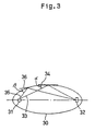
- FIG. 3 schematically shows the ellipsoid of revolution type reflecting mirror
- numeral 31 is an X-ray source installed at the first focal point of the ellipsoid of revolution type reflecting mirror 30
- numeral 32 is a specimen installed at the second focal point of the mirror 30.
- the X-ray beams emitted from the X-ray source 31 those reflected on the reflecting surface of the mirror 30 are all converged to the specimen 32 surface.
- This invention has been made with the above-mentioned matter taken into account, and it is the main object of this invention to provide an X-ray converging mirror that can reflect X-ray beams satisfactorily in the X-ray irradiation position direction in the vicinity of the X-ray source.
- the present invention provides an X-ray converging mirror as specified in the claim.
- the reflectivity of X-ray beams in the vicinity of the X-ray source becomes high and the X-ray intensity increases as much. Consequently, it is possible to obtain an X-ray converging mirror with an excellent X-ray efficiency.
- FIG. 1 shows the principal portion of the X-ray analysis microscope with the X-ray channel according to this invention assembled.
- numeral 1 is a microfocus X-ray tube as an X-ray source, which comprises a filament 4 generating electron 3 and an X-ray target 6 for generating desired X-ray beams 5 by allowing the electron 3 to collide against the target and is housed in a container 2 held to a specified high vacuum.
- Numeral 7 is an X-ray transmission window comprising beryllium that allows the X-ray beams 5 generated at the X-ray target 6 to pass to the X-ray channel 8 (later discussed) side.
- Numeral 8 is an X-ray channel that guides the X-ray beams emitted from the microfocus X-ray tube 1 to the X-ray irradiation position direction, and comprises the material with a small amount of zinc added to, for example, silica glass.
- the X-ray channel 8 comprises an X-ray converging mirror 9 in the vicinity of the microfocus X-ray tube 1 and an X-ray channel portion 10 on the X-ray irradiation position side connected thereto.
- the X-ray channel portion 10 is equipped with the profile similar to that on the second focal point side of the ellipsoid of revolution type reflecting mirror 30 and is joined to the open side of the X-ray converging mirror 9 expressed by the Eq. (I).
- Numeral 11 is an XY-axis scanning stage provided on the other end side of the X-ray channel 8, and this XY-axis scanning stage 11 is held in such a manner that the X-ray beam from the X-ray tube 1 side converges to the surface of the specimen 12 placed on this, and in this embodiment, it is arranged in such a manner that the surface coincides with the focal point position of the X-ray channel portion 10.
- a scintillation detector for detecting the X-ray permeating the semiconductor detector or specimen 12 for detecting fluorescent X-rays is installed in such a manner to command the XY-axis scanning stage 11.
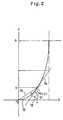
- the X-ray converging mirror 9 with a cross section given by Eq. ( I ) is arranged in such a manner that a microfocus X-ray tube 1 is located at the origin (position of reference symbol 0 in FIG. 2).
- the X-ray beam 5 generated at the microfocus X-ray tube 1 becomes fine X-ray beam of high brightness with a diameter less than 10 ⁇ m by passing the X-ray channel 8.
- This fine X-ray beam 5 is applied to a specimen 12 placed on the XY-axis scanning stage 11, and the fluorescent X-ray generated from it is detected by a semiconductor detector and the X-ray that penetrates the specimen 12 is detected by a scintillation detector simultaneously, respectively. And by returning signals of each detector into images using the XY axis scanning signals, it is possible to obtain a mapping image of surface elements by fluorescent X-ray and a mapping image of internal construction by penetrating X-rays.
- the cross-sectional profile of X-ray converging mirror 9 located in the vicinity of the microfocus X-ray channel 1 is a curve expressed by the ( I )
- the reflectivity of X-ray beam 5 in the vicinity of the microfocus X-ray tube 1 becomes high, and the X-ray intensity increases as much. Consequently, the X-ray efficiency of the X-ray converging mirror 9 improves and the measuring accuracy of the X-ray analysis microscope improves.
- the X-ray converging mirror 9 is small as compared to the conventional X-ray converging mirror, and it is possible to make the X-ray analysis microscope compact.
- an ellipsoid of revolution type reflecting mirror is used for the X-ray channel portion 10 joined to the X-ray converging mirror 9, but needless to say, it is allowed to adopt the mirror of a profile conventionally used such as a paraboloid of revolution, etc.
- the X-ray converging mirror 9 of this invention is naturally able to be applied to other X-ray irradiation equipment using X-ray tubes other than the X-ray analysis microscopes.
Landscapes
- Physics & Mathematics (AREA)
- Spectroscopy & Molecular Physics (AREA)
- Engineering & Computer Science (AREA)
- General Engineering & Computer Science (AREA)
- High Energy & Nuclear Physics (AREA)
- Analysing Materials By The Use Of Radiation (AREA)
Claims (1)
- Konvergenzspiegel für Röntgenstrahlung (9), der in der Nähe einer Röntgenstrahlungsquelle (1) angeordnet ist, und Röntgenstrahlen reflektiert, die von der Röntgenstrahlungsquelle (1) in die Richtung der Röntgenstrahlungs-Bestrahlungsposition emittiert werden, dadurch gekennzeichnet, dass das Querschnittsprofil dieses Spiegels (9) durch eine Kurve gebildet ist, die durch die folgende Gleichung ausgedrückt wird:
Applications Claiming Priority (4)
| Application Number | Priority Date | Filing Date | Title |
|---|---|---|---|
| JP165002/97 | 1997-06-07 | ||
| JP16500297 | 1997-06-07 | ||
| JP9165002A JPH10339798A (ja) | 1997-06-07 | 1997-06-07 | X線集光用ミラー |
| US09/092,199 US6052431A (en) | 1997-06-07 | 1998-06-05 | X-ray converging mirror for an energy-dispersive fluorescent X-ray system |
Publications (2)
| Publication Number | Publication Date |
|---|---|
| EP0883136A1 EP0883136A1 (de) | 1998-12-09 |
| EP0883136B1 true EP0883136B1 (de) | 2002-09-18 |
Family
ID=26489902
Family Applications (1)
| Application Number | Title | Priority Date | Filing Date |
|---|---|---|---|
| EP98110318A Expired - Lifetime EP0883136B1 (de) | 1997-06-07 | 1998-06-05 | Konvergenz-Spiegel für Röntgenstrahlung |
Country Status (3)
| Country | Link |
|---|---|
| US (1) | US6052431A (de) |
| EP (1) | EP0883136B1 (de) |
| JP (1) | JPH10339798A (de) |
Cited By (1)
| Publication number | Priority date | Publication date | Assignee | Title |
|---|---|---|---|---|
| US7068754B2 (en) | 2003-06-30 | 2006-06-27 | Siemens Medical Solutions Usa, Inc. | System to generate therapeutic radiation |
Families Citing this family (22)
| Publication number | Priority date | Publication date | Assignee | Title |
|---|---|---|---|---|
| WO2000024029A1 (en) * | 1998-10-21 | 2000-04-27 | Koninklijke Philips Electronics N.V. | X-ray irradiation apparatus including an x-ray source provided with a capillary optical system |
| DE19926205C2 (de) * | 1999-06-09 | 2001-10-18 | Ulrich Gerhardt | Kapillare zur Abbildung von Objekten im Bereich des Vakuum-Ultravioletts |
| RU2180439C2 (ru) * | 2000-02-11 | 2002-03-10 | Кумахов Мурадин Абубекирович | Способ получения изображения внутренней структуры объекта с использованием рентгеновского излучения и устройство для его осуществления |
| US20030012336A1 (en) * | 2001-06-20 | 2003-01-16 | Cash Webster C. | X-ray concentrator for therapy |
| JP3699998B2 (ja) * | 2002-03-20 | 2005-09-28 | 国立大学法人東北大学 | 蛍光x線ホログラフィー装置、蛍光x線ホログラフィーおよび局所構造解析方法 |
| US7180981B2 (en) * | 2002-04-08 | 2007-02-20 | Nanodynamics-88, Inc. | High quantum energy efficiency X-ray tube and targets |
| US20090086899A1 (en) * | 2007-09-28 | 2009-04-02 | Searete Llc, A Limited Liability Corporation Of The State Of Delaware | Repositioning X-ray fluorescence visualizer, imager, or information provider |
| US7724867B2 (en) * | 2007-09-28 | 2010-05-25 | Invention Science Fund I, Llc | Proximity-based X-Ray fluorescence visualizer, imager, or information provider |
| US7653173B2 (en) * | 2007-09-28 | 2010-01-26 | Searete Llc | Combining X-ray fluorescence visualizer, imager, or information provider |
| US7660385B2 (en) * | 2007-09-28 | 2010-02-09 | Searete Llc | Time of flight aspects for X-Ray fluorescence visualizer, imager, or information provider |
| US8041005B2 (en) * | 2007-09-28 | 2011-10-18 | The Invention Science Fund I, Llc | X-ray fluorescence visualizer, imager, or information provider |
| US8000438B2 (en) * | 2007-09-28 | 2011-08-16 | The Invention Science Fund I, Llc | Tool based X-ray fluorescence visualizing, imaging, or information providing |
| US20090086903A1 (en) * | 2007-09-28 | 2009-04-02 | Searete LLC, a limited liability corporation of | Selective elemental color providing for X-ray fluorescence visualization, imaging, or information providing |
| US7702066B2 (en) * | 2007-09-28 | 2010-04-20 | Searete Llc | Portable aspects for x-ray fluorescence visualizer, imager, or information provider |
| US7738627B2 (en) * | 2007-09-28 | 2010-06-15 | The Invention Science Fund I, Llc | Geometric X-ray fluorescence visualizer, imager, or information provider |
| US7773722B2 (en) * | 2007-09-28 | 2010-08-10 | The Invention Science Fund I, Llc | Personal transportable X-ray fluorescence visualizing, imaging, or information providing |
| US7825376B2 (en) * | 2007-09-28 | 2010-11-02 | The Invention Science Fund I | Scintillator aspects for X-ray fluorescence visualizer, imager, or information provider |
| US7664224B2 (en) * | 2007-09-28 | 2010-02-16 | Searete Llc | X-ray fluorescence visualizing, imaging, or information providing of chemicals, compounds, or biological materials |
| US8068579B1 (en) * | 2008-04-09 | 2011-11-29 | Xradia, Inc. | Process for examining mineral samples with X-ray microscope and projection systems |
| US7972062B2 (en) * | 2009-07-16 | 2011-07-05 | Edax, Inc. | Optical positioner design in X-ray analyzer for coaxial micro-viewing and analysis |
| JP6082634B2 (ja) * | 2013-03-27 | 2017-02-15 | 株式会社日立ハイテクサイエンス | 蛍光x線分析装置 |
| JP6586778B2 (ja) * | 2015-05-28 | 2019-10-09 | 株式会社ニコン | X線装置および構造物の製造方法 |
Family Cites Families (3)
| Publication number | Priority date | Publication date | Assignee | Title |
|---|---|---|---|---|
| JPS62274716A (ja) * | 1986-05-23 | 1987-11-28 | Hitachi Ltd | X線露光装置 |
| EP0262834A2 (de) * | 1986-10-01 | 1988-04-06 | Ovonic Synthetic Materials Company, Inc. | Elektronenstrahlerzeuger in Kombination mit einem Fokussierungsring für Röntgenstrahlen |
| JP3141660B2 (ja) * | 1993-12-15 | 2001-03-05 | 株式会社ニコン | X線照射装置 |
-
1997
- 1997-06-07 JP JP9165002A patent/JPH10339798A/ja active Pending
-
1998
- 1998-06-05 EP EP98110318A patent/EP0883136B1/de not_active Expired - Lifetime
- 1998-06-05 US US09/092,199 patent/US6052431A/en not_active Expired - Fee Related
Cited By (1)
| Publication number | Priority date | Publication date | Assignee | Title |
|---|---|---|---|---|
| US7068754B2 (en) | 2003-06-30 | 2006-06-27 | Siemens Medical Solutions Usa, Inc. | System to generate therapeutic radiation |
Also Published As
| Publication number | Publication date |
|---|---|
| EP0883136A1 (de) | 1998-12-09 |
| US6052431A (en) | 2000-04-18 |
| JPH10339798A (ja) | 1998-12-22 |
Similar Documents
| Publication | Publication Date | Title |
|---|---|---|
| EP0883136B1 (de) | Konvergenz-Spiegel für Röntgenstrahlung | |
| US6965663B2 (en) | X-ray analysis apparatus and method | |
| EP0615123B1 (de) | Methode und vorrichtung zur oberflächenanalyse | |
| US6711234B1 (en) | X-ray fluorescence apparatus | |
| US6442231B1 (en) | Apparatus and method for improved energy dispersive X-ray spectrometer | |
| JP3752252B2 (ja) | 電気的に絶縁された標本表面の分析装置 | |
| US4814615A (en) | Method and apparatus for detecting defect in circuit pattern of a mask for X-ray exposure | |
| CN1176707A (zh) | 高能量小直径x射线束的毛细光学系统 | |
| US6577705B1 (en) | Combinatorial material analysis using X-ray capillary optics | |
| EP0314502B1 (de) | Röntgenstrahlbilder-Beobachtungsvorrichtung | |
| Bzhaumikhov et al. | Polycapillary conic collimator for micro-XRF | |
| US8416921B2 (en) | X-ray convergence element and X-ray irradiation device | |
| US20070183060A1 (en) | Mirror optic for near-field optical measurements | |
| JP2002528859A (ja) | 毛細管光学系を含むx源を有するx線照射装置 | |
| US4768878A (en) | Test arrangement for non-contacting identification of defects in non-structured surfaces | |
| US5739542A (en) | X-ray analyzing | |
| US20050226372A1 (en) | X-ray image magnifying device | |
| CN112014418B (zh) | 一种电子束激发荧光收集耦合用离轴反射面镜组件及方法 | |
| JP3403454B2 (ja) | 反射電子検出装置 | |
| JP2995361B2 (ja) | 照射領域モニター付きx線照射装置 | |
| US6777678B1 (en) | Sample-stage for scanning electron microscope | |
| JPH08146197A (ja) | 反射鏡固定方法及び反射鏡ホルダー | |
| DE69807989T2 (de) | Konvergenz-Spiegel für Röntgenstrahlung | |
| JP2000329713A (ja) | X線分析装置 | |
| JPH082603Y2 (ja) | X線分析装置 |
Legal Events
| Date | Code | Title | Description |
|---|---|---|---|
| PUAI | Public reference made under article 153(3) epc to a published international application that has entered the european phase |
Free format text: ORIGINAL CODE: 0009012 |
|
| AK | Designated contracting states |
Kind code of ref document: A1 Designated state(s): DE FR GB |
|
| AX | Request for extension of the european patent |
Free format text: AL;LT;LV;MK;RO;SI |
|
| 17P | Request for examination filed |
Effective date: 19981112 |
|
| AKX | Designation fees paid |
Free format text: DE FR GB |
|
| GRAG | Despatch of communication of intention to grant |
Free format text: ORIGINAL CODE: EPIDOS AGRA |
|
| 17Q | First examination report despatched |
Effective date: 20010821 |
|
| GRAG | Despatch of communication of intention to grant |
Free format text: ORIGINAL CODE: EPIDOS AGRA |
|
| GRAG | Despatch of communication of intention to grant |
Free format text: ORIGINAL CODE: EPIDOS AGRA |
|
| GRAH | Despatch of communication of intention to grant a patent |
Free format text: ORIGINAL CODE: EPIDOS IGRA |
|
| GRAH | Despatch of communication of intention to grant a patent |
Free format text: ORIGINAL CODE: EPIDOS IGRA |
|
| GRAA | (expected) grant |
Free format text: ORIGINAL CODE: 0009210 |
|
| AK | Designated contracting states |
Kind code of ref document: B1 Designated state(s): DE FR GB |
|
| REG | Reference to a national code |
Ref country code: GB Ref legal event code: FG4D |
|
| REF | Corresponds to: |
Ref document number: 69807989 Country of ref document: DE Date of ref document: 20021024 |
|
| ET | Fr: translation filed | ||
| PLBE | No opposition filed within time limit |
Free format text: ORIGINAL CODE: 0009261 |
|
| STAA | Information on the status of an ep patent application or granted ep patent |
Free format text: STATUS: NO OPPOSITION FILED WITHIN TIME LIMIT |
|
| 26N | No opposition filed |
Effective date: 20030619 |
|
| PGFP | Annual fee paid to national office [announced via postgrant information from national office to epo] |
Ref country code: DE Payment date: 20070531 Year of fee payment: 10 |
|
| PGFP | Annual fee paid to national office [announced via postgrant information from national office to epo] |
Ref country code: GB Payment date: 20070530 Year of fee payment: 10 |
|
| PGFP | Annual fee paid to national office [announced via postgrant information from national office to epo] |
Ref country code: FR Payment date: 20070608 Year of fee payment: 10 |
|
| GBPC | Gb: european patent ceased through non-payment of renewal fee |
Effective date: 20080605 |
|
| REG | Reference to a national code |
Ref country code: FR Ref legal event code: ST Effective date: 20090228 |
|
| PG25 | Lapsed in a contracting state [announced via postgrant information from national office to epo] |
Ref country code: DE Free format text: LAPSE BECAUSE OF NON-PAYMENT OF DUE FEES Effective date: 20090101 |
|
| PG25 | Lapsed in a contracting state [announced via postgrant information from national office to epo] |
Ref country code: GB Free format text: LAPSE BECAUSE OF NON-PAYMENT OF DUE FEES Effective date: 20080605 |
|
| PG25 | Lapsed in a contracting state [announced via postgrant information from national office to epo] |
Ref country code: FR Free format text: LAPSE BECAUSE OF NON-PAYMENT OF DUE FEES Effective date: 20080630 |