EP0882482A2 - Verfahren zum Trennen eines Gemisches, Vorrichtung zur Durchführung des Verfahrens und Verwendung der Vorrichtung - Google Patents
Verfahren zum Trennen eines Gemisches, Vorrichtung zur Durchführung des Verfahrens und Verwendung der Vorrichtung Download PDFInfo
- Publication number
- EP0882482A2 EP0882482A2 EP98810513A EP98810513A EP0882482A2 EP 0882482 A2 EP0882482 A2 EP 0882482A2 EP 98810513 A EP98810513 A EP 98810513A EP 98810513 A EP98810513 A EP 98810513A EP 0882482 A2 EP0882482 A2 EP 0882482A2
- Authority
- EP
- European Patent Office
- Prior art keywords
- zone
- mixture
- condensation
- heat flow
- component
- Prior art date
- Legal status (The legal status is an assumption and is not a legal conclusion. Google has not performed a legal analysis and makes no representation as to the accuracy of the status listed.)
- Withdrawn
Links
Images





Classifications
-
- F—MECHANICAL ENGINEERING; LIGHTING; HEATING; WEAPONS; BLASTING
- F28—HEAT EXCHANGE IN GENERAL
- F28D—HEAT-EXCHANGE APPARATUS, NOT PROVIDED FOR IN ANOTHER SUBCLASS, IN WHICH THE HEAT-EXCHANGE MEDIA DO NOT COME INTO DIRECT CONTACT
- F28D7/00—Heat-exchange apparatus having stationary tubular conduit assemblies for both heat-exchange media, the media being in contact with different sides of a conduit wall
- F28D7/10—Heat-exchange apparatus having stationary tubular conduit assemblies for both heat-exchange media, the media being in contact with different sides of a conduit wall the conduits being arranged one within the other, e.g. concentrically
- F28D7/106—Heat-exchange apparatus having stationary tubular conduit assemblies for both heat-exchange media, the media being in contact with different sides of a conduit wall the conduits being arranged one within the other, e.g. concentrically consisting of two coaxial conduits or modules of two coaxial conduits
-
- B—PERFORMING OPERATIONS; TRANSPORTING
- B01—PHYSICAL OR CHEMICAL PROCESSES OR APPARATUS IN GENERAL
- B01D—SEPARATION
- B01D5/00—Condensation of vapours; Recovering volatile solvents by condensation
- B01D5/0003—Condensation of vapours; Recovering volatile solvents by condensation by using heat-exchange surfaces for indirect contact between gases or vapours and the cooling medium
-
- B—PERFORMING OPERATIONS; TRANSPORTING
- B01—PHYSICAL OR CHEMICAL PROCESSES OR APPARATUS IN GENERAL
- B01D—SEPARATION
- B01D5/00—Condensation of vapours; Recovering volatile solvents by condensation
- B01D5/0003—Condensation of vapours; Recovering volatile solvents by condensation by using heat-exchange surfaces for indirect contact between gases or vapours and the cooling medium
- B01D5/0012—Vertical tubes
-
- B—PERFORMING OPERATIONS; TRANSPORTING
- B01—PHYSICAL OR CHEMICAL PROCESSES OR APPARATUS IN GENERAL
- B01D—SEPARATION
- B01D5/00—Condensation of vapours; Recovering volatile solvents by condensation
- B01D5/0033—Other features
- B01D5/0039—Recuperation of heat, e.g. use of heat pump(s), compression
-
- B—PERFORMING OPERATIONS; TRANSPORTING
- B01—PHYSICAL OR CHEMICAL PROCESSES OR APPARATUS IN GENERAL
- B01D—SEPARATION
- B01D5/00—Condensation of vapours; Recovering volatile solvents by condensation
- B01D5/0078—Condensation of vapours; Recovering volatile solvents by condensation characterised by auxiliary systems or arrangements
- B01D5/0093—Removing and treatment of non condensable gases
-
- F—MECHANICAL ENGINEERING; LIGHTING; HEATING; WEAPONS; BLASTING
- F28—HEAT EXCHANGE IN GENERAL
- F28F—DETAILS OF HEAT-EXCHANGE AND HEAT-TRANSFER APPARATUS, OF GENERAL APPLICATION
- F28F27/00—Control arrangements or safety devices specially adapted for heat-exchange or heat-transfer apparatus
Definitions
- the invention relates to a method according to the preamble of patent claim 1 , a device for carrying out the method according to the preamble of patent claim 8 and a use of this device according to the preamble of patent claim 14 .
- a first purpose is the first component, i.e. the gas or if necessary, clean the gas mixture from the steam; a second purpose is the second Recycle component that would be volatile in the gas, both for reasons of Litigation as well as for reasons of recycling in general in liquid Is brought into shape.
- the only example of such a process is recovery of solvents, although the procedure is basically for each separation of steam / gas mixtures.
- a first heat flow is used to separate the mixture or mixture flow withdrawn, which is large enough to condense the second component.
- the aim is that the condensate formed in the second component precipitates on a cooling surface, from where it is, for example, in a vessel collects. It was recognized some time ago that this procedure does not it is possible to separate the mixture completely or only sufficiently achieve this for the following reason: the second component does not only work as Condensate down on the cooling surface, but small liquid drops form in the mixture, so that a fog arises, the formation of which is somewhat oversaturated presupposes and through homogeneous and / or heterogeneous condensation nuclei is triggered.
- the fog particles or liquid drops are so fine that they are not separated but carried on by the gas stream and therefore also be called aerosols. This will both cleanse the effect first component as well as the recovery of the second component only partially reached.
- attempts are often made to filter the fog particles to filter out of the gas stream, which, for various reasons, turns out to be proves problematic.
- a previously proposed electrical heating of the mixture for example by means of a heating wire device, is not permitted in all cases in which there is a risk of explosion.
- Heating the mixture by means of a separate heating medium as has been known for a long time from SU-A-1152605 , is complex in terms of apparatus, and in principle the heat to be supplied causes additional expenditure in terms of energy.
- the first object of the invention is therefore seen as a method of the beginning to propose the type mentioned, which avoids the disadvantages mentioned.
- the second The object of the invention is to provide a device of the type mentioned create, which are used to carry out the inventive method can.
- the third task concerns the use of the new device.
- the method according to the invention can be used to prevent the formation of fog required heat flow so that no effort for a heating medium must be operated; this means that there is no additional heat supply Energy carrier and no additional energy expenditure is required, whereby in Within the scope of the present invention, the ambient atmosphere or ambient air is not regarded as an additional heating medium or as an additional energy source.
- the required one Heat flow that is added to the mixture from the environment is below the ambient temperature.
- third variant of the method which is then carried out can become if the ambient temperature is lower than the temperature of the Condensation zone, the mixture itself is used as a carrier of the heat to be supplied; the mixture has a temperature at the beginning of the process, which is above the Temperature of the condensation zone. Part of the incoming convective mixture The heat imparted is according to the invention on the already cooled mixture given, which is thereby heated.
- the device according to the invention has a flow channel or a sequence of Flow cross-sections on which the mixture flows and both from one Cooling wall and as is also delimited by a heating wall, so that at least one condensation zone for the mixture arises.
- a suitable cooling medium flows.
- the heating wall has a warm zone in which the temperature is higher than in the mixture in the condensation zone.
- the cooling wall has one of the condensation zone facing cooling surface on which the mixture already condensed steam precipitates as condensate.
- the heating wall has one of the Condensation zone facing heating surface on which the mixture heats up.
- the warm zone is free of heating agents, which means that none additional heating medium or no additional energy source - with the exception of possibly Ambient atmosphere - is necessary because the second heat flow with which the Mixture is heated, is supplied in a different way.
- the apparatus structure of the device in and of itself and the installation effort around Device greatly simplified.
- the Warm zone formed by the environment which, as mentioned above, is only possible is when the temperature in the condensation zone is lower than the ambient temperature.
- the heating wall thus forms the outer wall of the device in this case; since they are the Permitting heat transfer can - which is another constructive advantage - on any isolation can be dispensed with.
- a second embodiment of the device according to the invention is constructive delimited a warm zone; an actual additional one does not flow through them Heating medium that would have to be supplied specifically, only that the device anyway surrounding medium, so generally the ambient air.
- thermodynamic approach in terms of a theoretically correct thermodynamic approach, however can be said that in the two embodiments of the device according to the invention nevertheless a heating medium, namely the ambient air, is used to supply heat.
- a heating medium namely the ambient air
- the surrounding area Heat is removed, which may result in increased room heating.
- the warm zone formed by a zone through which the mixture flows.
- the mixture flows thereby through the warm zone, there gives heat via the heating wall, more precisely the second one Heat flow to the mixture already in the condensation zone cools down doing so, and then enters the condensation zone.
- the condensation zone gives the mixture heat through the cooling wall, namely the first heat flow to the Cooling medium, whereby it cools, so that the second component gradually after condensation on the cooling surface.
- heat arrives, namely the already mentioned second heat flow, which is less than the first heat flow, from now mixture in the warm zone through the heating wall into the mixture of the condensation zone and heated this. Also with this training there is no additional Heating medium, not even ambient air, is required.
- the supply of the second heat flow to the warm zone, but not to the condensation zone, is done convectively or in a regenerative one Way, namely by the mixture itself. This will not only be in the condensation zone located mixture also heats the mixture located in the warm zone Mixture pre-cooled.
- the device can be designed such that the flow cross sections of the condensation zone touch the cooling wall and the heating wall simultaneously or alternatively. in the first In the second case, the mixture is heated simultaneously with the condensation In this case, condensation and heating take place alternately or sequentially. It is also possible to provide permanent cooling and sequential cooling.
- the method according to the invention is also carried out in a batch operation could be done, it is generally done continuously in a device that, in principle is a kind of 'double' heat exchanger.
- the transition of the first heat flow takes place each from the condensation zone to the coolant zone and the transition of the second Heat flows from the warm zone to the condensation zone.
- three media, namely ambient atmosphere, mixture and cooling medium are in the last-mentioned embodiment of the device according to the invention only two media in play, namely the mixture and the coolant.
- the flow channels which form the warm zone, the condensation zone and the coolant zone, can - like the flow channels of heat exchangers - relative to each other in direct current and / or run in cross flow and / or in counter flow. All the specialist for Known knowledge and design variants of heat exchangers are appropriate also valid for the device according to the invention.
- the condensation zone can continue after the condensation of the second component Heat is removed, leaving the second component on the cooling surface in the solid Condition passes.
- the method according to the invention and the device according to the invention are preferred used to recover solvents from gases.
- Common procedure is air or nitrogen and the second component a common solvent.
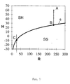
- the diagram according to FIG. 1 applies to a mixture, wherein the mass flow ratio R of the second component II to be liquefied is plotted horizontally in g to the first, ie permanently gaseous component I in kg, while the corresponding enthalpy flow stream H is plotted in kJ / kg the first component I is applied.
- the curve s is the saturation line which separates the states of overheating SH from the states of supersaturation SS .
- a decrease in R takes place simultaneously with the condensation of the second component. In order to prevent the formation of unwanted fog, the process must in principle be carried out so that the line s is not undercut.
- the initial state A is obtained by pre-cooling the mixture in the warm zone to the intermediate state B and then to the final state C , whose ratio R is generally predetermined and should be as small as possible; thereby follow the line s from B to C if possible.
- the initial state A can also be on or near the line s .
- FIG. 2 shows a flow channel for the mixture, which forms a condensation zone 10 , a cooling wall 12 with a condensation surface 12.1 , on which a film of condensate 13 is located, and a heating wall 14 with a heating surface 14.1 .
- the cooling wall 12 separates the condensation zone 10 from the coolant zone 16 , in which a cooling medium is located, and the heating wall 14 separates the condensation zone 10 from a warm zone 18 , in which the temperature is higher than in the condensation zone 10 .
- a first heat flow Q 1 passes from the condensation zone 10 into the cooling zone 16
- a second, substantially lower heat flow Q2 passes from the warm zone 18 into the condensation zone 10 .
- the mixture initially carries an enthalpy stream H a ; in the condensation of the second component to the condensate 13 , this enthalpy flow H a decreases by H k to H z . the heat flow corresponding to the enthalpy flow H k being released through the cooling wall 12 to the cooling medium.
- the condensation zone 10 is supplied with the second heat flow Q 2 through the heating wall 14 , which together with the heat flow corresponding to the enthalpy flow H k ultimately forms the first heat flow Q 1 given off to the coolant zone 16 .
- Fig. 3 shows a schematic cross section through a highly simplified first embodiment of the inventive device, with the traversed by the mixture to be separated condensation zone 10, which from the cooling wall 12 with the condensation zone 10 facing the condensation surface 12.1 as well as the heating wall 14 to the condensation zone 10 facing heating surface 14.1 is limited.
- Inside the cooling wall 12 there is the cooling zone 16 with the cooling medium, and outside the heating wall 14 there is the warm zone 18 in which the temperature is higher than in the condensation zone 10 .
- the warm zone 18 can be formed by the surroundings, an outer wall 20 is not required, or it can be a section of the entire flow channel of the mixture through which the mixture itself flows and precedes the condensation zone 10 .
- FIG. 4 shows purely qualitatively the temperature profile in the heat exchange area M of an inventive device according to FIG. 5 .
- the mixture or the cleaned first component are shown schematically with solid lines, the condensed second component with a double line and the coolant with dashed lines; the directions of flow are indicated by arrows.
- the mixture When entering, corresponding to the initial state A according to FIG. 1 , the mixture has the temperature T 1 . It is then, before it reaches the condensation zone, precooled to the temperature T 2 corresponding to the intermediate state B in FIG. 1 by releasing the second heat flow Q 2 to the mixture in the condensation zone.
- the mixture in the condensation zone initially has the temperature T 3 , which is equal to the temperature T 2 ; it absorbs the heat flow Q 2 , but at the same time the heat flow Q 1 , comprising at least the temporal condensation heat for the second component and the supplied second heat flow Q 2 , is withdrawn from it, so that the condensation of the second component takes place, the temperature being at T 4 drops.
- the temperature of the coolant is T 6 at the inlet and T 7 at the outlet; T 6 and T 7 can be the same.
- the use of the process according to the invention for the separation of a mixture of nitrogen as the first component I and methanol as the second component II should be mentioned numerically.
- the ratio of methanol to nitrogen was thus 0.235 kg methanol / kg nitrogen and the ratio of methanol to mixture was 0.190 kg methanol / kg mixture.
- the temperature T 1 was 328 ° K or 55 ° C at an inlet pressure of 1 bar.
- the cooling surface was 28 square meters, and the coolant temperatures T 6 and T 7 were 258 ° K and -15 ° C.
- the purified nitrogen was finally obtained with a residual amount Methanol, the ratio of methanol to nitrogen still being 0.029 kg of methanol / kg of nitrogen, which corresponds to a purity of nitrogen of 97.2%.
- the temperature T4 was 276 ° K, ie 3 ° C.
- the second heat flow Q 2 through the heating wall was 12.9 kW and the first heat flow Q 1 through the cooling wall was 69.5 kW.
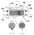
- the exemplary embodiment of the device according to the invention shown in FIG. 6 comprises a container 100 in which the heat exchange area M is arranged.
- the container 100 has an inlet 102 for the hot mixture, an outlet 104 for the mixture pre-cooled by the heat flow Q 2 , an inlet 106 for this pre-cooled mixture, an outlet 108 for the cleaned first component, an outlet 110 for the condensed second Component and an inlet 112 and an outlet 114 for the coolant.
- the flow directions are indicated by arrows.
- Baffles 116 are further arranged in the container, by means of which a parallel flow, that is to say a direct current or counter current, is locally deflected into a cross flow in order to improve the heat transfer.
- FIGS. 7A and 7B show cross sections through the container 100 , with heating tubes 120 and cooling tubes 122 , the heating tubes 120 having a checkered pattern and the cooling tubes 122 having normal hatching.
- the tubes which heat the condensation zone that is to say the tubes between the inlet 106 and the outlet 108 , are referred to as heating tubes 120
- those tubes which cool the condensation zone that is to say the tubes which carry the coolant, are referred to as cooling tubes 122 .
- 6, 7A and 7B it can be seen that the condensation zone is heated in cocurrent / crossflow and the cooling of the condensation zone in countercurrent / crossflow.
- FIG. 8 shows a second exemplary embodiment of the device according to the invention, which, like the exemplary embodiment according to FIG. 6, comprises a container 100 .
- the container 100 has an inlet 102 for the warm mixture, an outlet 104 for the mixture pre-cooled by the delivery of the second heat flow Q 2 to the condensation zone 10 , an inlet 106 for this pre-cooled mixture, an outlet 108 for the cleaned first component, an outlet 110 for the condensed second component and an inlet 112 and an outlet 114 for the coolant.
- Baffles 116 are arranged in the container. In this embodiment, the condensation takes place in annular gaps 124 .
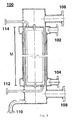
- FIG. 9 A third exemplary embodiment of the device according to the invention is shown in FIG. 9 , likewise with a container 100 , comprising an inlet 102 for the warm mixture, an outlet 104 for the mixture pre-cooled by the release of the heat flow Q 2 , an inlet 106 for this pre-cooled mixture, an outlet 108 for the cleaned first component, an outlet 110 for the condensed second component, an inlet 112 and an outlet 114 for the coolant, and a heat exchange zone M.
- the container 100 can be installed vertically with the outlet 110 for the condensate at the bottom or horizontally, in which case an outlet channel for the condensate must be provided.
- FIG. 10 shows a fourth exemplary embodiment of the device according to the invention.
- This has a container 100 , with an inlet 102 for the warm mixture, an outlet 104 for the mixture pre-cooled by the release of the heat flow Q 2 , an inlet 106 for this pre-cooled mixture, an outlet 108 for the cleaned first component, an outlet 110 for the condensed second component, an inlet 112 and an outlet 114 for the coolant and a heat exchange zone M.
- the condensation zone 10 or a plurality of parallel condensation zones, and the warm zone 18 , or a plurality of parallel warm zones, are separated from one another by flat or at least approximately flat heating walls, the heating surfaces 14.1 of which face the condensation zones 10 .
- the coolant zone 16 or a total of several parallel coolant zones are located in the condensation zones 10 , the cooling surfaces 12.1 of the coolant zones on both sides facing the respective condensation zones 10 .
- the coolant zones are formed by two plates which are connected to one another at points, for example by welding, and along their edges, the cooling walls being cambered.
- the new device is particularly suitable for separating mixtures in which the first component is a gas such as nitrogen or air and the second component Solvents such as methanol or another alcohol, dichloromethylene or trichloromethylene or another chlorinated hydrocarbon compound, the above list is not final.
- the first component is a gas such as nitrogen or air
- the second component Solvents such as methanol or another alcohol, dichloromethylene or trichloromethylene or another chlorinated hydrocarbon compound, the above list is not final.
- the exemplary embodiments described form only a small selection of those in the frame possible implementations of the device according to the invention.
- Especially structurally identical devices depending on the substances, temperatures, Pressures and speeds on both cocurrent and countercurrent be switched. It is only essential that the condensation of the second component and thus the separation of the two components to a sufficient extent and below Avoidance or reduction of fog formation takes place without the necessary Heat supply an additional heating medium, except possibly ambient air - What must be used, as intended, both constructively and energetically represents a significant advance over the prior art.
Landscapes
- Chemical & Material Sciences (AREA)
- Chemical Kinetics & Catalysis (AREA)
- Engineering & Computer Science (AREA)
- Physics & Mathematics (AREA)
- Thermal Sciences (AREA)
- Mechanical Engineering (AREA)
- General Engineering & Computer Science (AREA)
- Physical Or Chemical Processes And Apparatus (AREA)
- Vaporization, Distillation, Condensation, Sublimation, And Cold Traps (AREA)
Abstract
Description
- Fig. 1
- Ein Enthalpiestrom/Massenstrom-Verhältnis-Diagramm zur Erläuterung des durch die Erfindung gelösten Problems;
- Fig. 2
- Die Wärme- bzw. Enthalpieströme übergänge des erfindungsgemässen Verfahrens, in schematischer Darstellung;
- Fig. 3
- Eine schematische Darstellung der erfindungsgemässen Vorrichtung zur Erläuterung des erfindungsgemässen Verfahrens;
- Fig. 4
- die Temperaturverläufe im Gemisch und im Kühlmittel bei der Durchführung des erfindungsgemässen Verfahrens;
- Fig. 5
- eine erfindungsgemässen Vorrichtung, zur Durchführung des gemäss Fig. 2 und Fig. 4 dargestellten Verfahrens, in stark vereinfachter, schematischer Darstellung;
- Fig. 6
- ein erstes Ausführungsbeispiel der erfindungsgemässen Vorrichtung;
- Fig. 7A
- einen Schnitt längs der Linie X-X der Fig. 6;
- Fig. 7B
- einen Schnitt längs der Linie Y-Y der Fig. 6;
- Fig. 8
- ein zweites Ausführungsbeispiel der erfindungsgemässen Vorrichtung;
- Fig. 9
- ein drittes Ausführungsbeispiel der erfindungsgemässen Vorrichtung; und
- Fig. 10
- ein viertes Ausführungsbeispiel der erfindungsgemässen Vorrichtung; und
- Fig. 11
- einen Schnitt längs der Linie Z-Z der Fig. 10.
Claims (14)
- Verfahren zum Trennen eines Gemisches aus zwei Komponenten (I, II), von welchen die erste Komponente (I) gasförmig und die zweite Komponente (II) dampfförmig ist, wobei dem strömenden Gemisch ein erster Wärmestrom (Q1 ) entzogen wird, welcher sich aus mindestens der zeitlichen Verdampfungswärme der zweiten Komponente (II) und einem dem Gemisch zugeführten zweiten Wärmestrom (Q2 ) zusammensetzt, der die mindestens teilweise Verhinderung von Nebelbildung aus der zweiten Komponente (II) im Gemisch bezweckt,
dadurch gekennzeichnet,
dass der zweite Wärmestrom (Q2 ) aufwandslos zugeführt wird. - Verfahren nach Patentanspruch 1,
dadurch gekennzeichnet,
dass der zweite Wärmestrom (Q2 ) aus der im wesentlichen ruhenden Umgebungsatmosphäre, insbesondere der Umgebungsluft, zugeführt wird. - Verfahren nach Patentanspruch 1,
dadurch gekennzeichnet,
dass der zweite Wärmestrom (Q2 ) aus der strömenden Umgebungsatmosphäre, insbesondere der Umgebungsluft, zugeführt wird. - Verfahren nach Patentanspruch 1,
dadurch gekennzeichnet,
dass die zweite Wärmestrom (Q2 ) regenerativ aus dem Gemisch zugeführt wird. - Verfahren nach Patentanspruch 1,
dadurch gekennzeichnet,
dass die Abfuhr des ersten Wärmestroms (Q1 ) und/oder die Zufuhr des zweiten Wärmestroms (Q2 ) kontinuierlich oder sequentiell erfolgen. - Verfahren nach mindestens einem der Ansprüche 1 bis 5,
dadurch gekennzeichnet,
dass die kondensierte zweite Komponente (II) durch Abgabe eines dritten Wärmestroms in ihren festen Zustand übergeht. - Verfahren nach mindestens einem der Patentansprüche 1 bis 6,
dadurch gekennzeichnet,
dass es nach einer Massen-, Enthalpie- und Wärmestromkonfiguration durchgeführt wird, welche einer der für Wärmetauscher üblichen Massen-, Enthalpie- und Wärmestromkonfigurationen entsprechen. - Vorrichtung zum Trennen eines Gemisches aus zwei Komponenten (I, II), von welchen die erste gasförmig und die zweite dampfförmig ist, mit einer vom Gemisch durchströmten Kondensationszone (10), welche an eine Kühlwand (12) und an eine Heizwand (14) grenzt, wobei die Kühlwand (12) eine der Kondensationszone (10) zugewandte Kondensationsfläche (12.1) aufweist und die Kondensationszone (10) von einer von Kühlmittel mit tieferer Temperatur als die Kondensationszone (10) durchströmten Kühlmittelzone (16) trennt, und wobei die Heizwand (14) eine der Kondensationszone (18) zugewandte Heizfläche (14.1) aufweist und die Kondensationszone (10) von einer Warmzone (18) trennt, in welcher eine höhere Temperatur herrscht als in der Kondensationszone (10),
dadurch gekennzeichnet,
dass die Warmzone (18) von zusätzlichem Heizmedium frei ist. - Vorrichtung nach Patentanspruch 8,
dadurch gekennzeichnet,
dass die Warmzone (18) die Umgebungsatmosphäre, insbesondere die im wesentlichen ruhende Umgebungsluft ist. - Vorrichtung nach Patentanspruch 8,
dadurch gekennzeichnet,
dass die Warmzone (18) durch eine Wandung von der Umgebung getrennt und von Umgebungsatmosphäre, insbesondere Umgebungsluft, durchströmt ist. - Vorrichtung nach Patentanspruch 8,
dadurch gekennzeichnet,
dass die Warmzone (18) eine vom Gemisch durchströmte, der Kondensationszone (10) vorgeschaltete Zone ist. - Vorrichtung nach mindestens einem der Patentansprüche 8 bis 11,
dadurch gekennzeichnet,
dass jeder Strömungsquerschnitt des Gemisches simultan oder alternativ die Kühlwand (12) und die Heizwand (14) berührt, so dass die Wärmeabgabe aus der Kondensationszone (10) an die Kühlmittelzone (16) und/oder die Wärmezufuhr an die Kondensationszone (10) aus der Warmzone (18) simultan oder abwechselnd erfolgt. - Vorrichtung nach mindestens einem der Patentansprüche 7 bis 12,
dadurch gekennzeichnet,
dass die die Warmzone (18), die Kondensatinszone (10) und die Kühlmittelzone (16) bildenden Strömungskanäle des Gemisches bzw. des Kühlmittels relativ zueinander im Gleichstrom und/oder im Gegenstrom und/oder im Querstrom verlaufen. - Verwendung der Vorrichtung nach einem der Patentansprüche 7 bis 12,
dadurch gekennzeichnet,
dass die erste Komponente ein Gas, insbesondere Luft oder Stickstoff, und die zweite Komponente ein Lösungsmittel ist.
Applications Claiming Priority (3)
| Application Number | Priority Date | Filing Date | Title |
|---|---|---|---|
| CH1339/97 | 1997-06-04 | ||
| CH133997A CH696874A5 (de) | 1997-06-04 | 1997-06-04 | Verfahren zum Trennen eines Gemisches, Vorrichtung zur Durchführung des Verfahrens und Verwendung der Vorrichtung. |
| CH133997 | 1997-06-04 |
Publications (2)
| Publication Number | Publication Date |
|---|---|
| EP0882482A2 true EP0882482A2 (de) | 1998-12-09 |
| EP0882482A3 EP0882482A3 (de) | 2000-05-10 |
Family
ID=4208175
Family Applications (1)
| Application Number | Title | Priority Date | Filing Date |
|---|---|---|---|
| EP98810513A Withdrawn EP0882482A3 (de) | 1997-06-04 | 1998-06-04 | Verfahren zum Trennen eines Gemisches, Vorrichtung zur Durchführung des Verfahrens und Verwendung der Vorrichtung |
Country Status (2)
| Country | Link |
|---|---|
| EP (1) | EP0882482A3 (de) |
| CH (1) | CH696874A5 (de) |
Family Cites Families (3)
| Publication number | Priority date | Publication date | Assignee | Title |
|---|---|---|---|---|
| SU1152605A1 (ru) * | 1983-03-28 | 1985-04-30 | Предприятие П/Я А-7850 | Десублиматор |
| EP0164340A1 (de) * | 1983-12-07 | 1985-12-18 | Licencia Talalmanyokat Ertekesitö Vallalat | Verfahren und rekuperationswärmeaustauscheinrichtung zur gewinnung von verunreinigungen aus verunreinigter warmluft, insbesondere aus rauchgasen, und zur reduktion der schornsteinkorrosion |
| GB2172975B (en) * | 1985-03-26 | 1988-11-23 | Robert William Macintosh | Central heating enclosed dryer |
-
1997
- 1997-06-04 CH CH133997A patent/CH696874A5/de not_active IP Right Cessation
-
1998
- 1998-06-04 EP EP98810513A patent/EP0882482A3/de not_active Withdrawn
Also Published As
| Publication number | Publication date |
|---|---|
| CH696874A5 (de) | 2008-01-15 |
| EP0882482A3 (de) | 2000-05-10 |
Similar Documents
| Publication | Publication Date | Title |
|---|---|---|
| DE1551581A1 (de) | Verfahren zum Abscheiden von Stickstoff aus Luft | |
| DE4202802A1 (de) | Vorrichtung zum kuehltrocknen von gasen | |
| DE69416233T2 (de) | Kristallisierungsverfahren und Vorrichtung | |
| DE2606364A1 (de) | Verfahren zur stofftrennung aus einem fluessigen gemisch durch fraktionierte kristallisation | |
| DE69612038T2 (de) | Rückgewinnung von flüchtigen organischen Verbindungen aus Abgasen | |
| EP0153984A2 (de) | Verfahren und Vorrichtung zur Gewinnung von C3+-Kohlenwasserstoffen | |
| EP0439731A1 (de) | Verfahren zur thermischen Trennung einer Wasser/Àlemulsion | |
| DE2155366C2 (de) | Verfahren zum Trennen einer vorwiegend Stickstoff und Methan enthaltenden hochgespannten Erdgas-Beschickungsmischung | |
| DE1203226B (de) | Vorrichtung zur Abscheidung sublimierbarer Substanzen | |
| EP0241817A2 (de) | Verfahren und Vorrichtung zur Erzeugung von Stickstoff | |
| DE3703706C2 (de) | Verfahren und Anordnung zum Reinigen eines kontaminierten Heissgasstromes | |
| DE1268162B (de) | Verfahren zum Zerlegen eines Gasgemisches | |
| DE453407C (de) | Trennung von Wasserstoff enthaltenden Gasgemischen | |
| DE3107151A1 (de) | Verfahren und vorrichtung zur verfluessigung und zerlegung von luft | |
| DE3127039A1 (de) | "verfahren und waermetauscher zum sieden von fluessiggas" | |
| EP0882482A2 (de) | Verfahren zum Trennen eines Gemisches, Vorrichtung zur Durchführung des Verfahrens und Verwendung der Vorrichtung | |
| DE19521673C2 (de) | Verfahren zur regenerativen Abluftreinigung | |
| DE3152372C2 (de) | ||
| DE2132715A1 (de) | Anlage und verfahren zur kontinuierlichen hochdruckreinigung von gasen | |
| DE550686C (de) | Verfahren zum Zerlegen von Gasgemischen unter Abscheidung der leicht kondensierbarenBestandteile in fluessiger oder fester Form | |
| DE3213578C2 (de) | Vorrichtung zum Destillieren von Schieferöl aus Ölschiefer | |
| DE1137054B (de) | Vorrichtung zum Ausfrieren von Bestandteilen aus einem Gasgemisch | |
| DE1601247A1 (de) | Verfahren zum Abkuehlen und gleichzeitigen Reinigen von Gasgemischen | |
| DE1645811A1 (de) | Verfahren und Vorrichtung zur Reinigung von Erdgas | |
| DE102021112339A1 (de) | Verfahren, Inertisierungsvorrichtung und Inertgasbox zur Herstellung einer Inertgasatmosphäre |
Legal Events
| Date | Code | Title | Description |
|---|---|---|---|
| PUAI | Public reference made under article 153(3) epc to a published international application that has entered the european phase |
Free format text: ORIGINAL CODE: 0009012 |
|
| AK | Designated contracting states |
Kind code of ref document: A2 Designated state(s): CH DE FR GB LI |
|
| AX | Request for extension of the european patent |
Free format text: AL;LT;LV;MK;RO;SI |
|
| PUAL | Search report despatched |
Free format text: ORIGINAL CODE: 0009013 |
|
| AK | Designated contracting states |
Kind code of ref document: A3 Designated state(s): AT BE CH CY DE DK ES FI FR GB GR IE IT LI LU MC NL PT SE |
|
| AX | Request for extension of the european patent |
Free format text: AL;LT;LV;MK;RO;SI |
|
| RIC1 | Information provided on ipc code assigned before grant |
Free format text: 7B 01D 5/00 A, 7F 28D 7/10 B |
|
| 17P | Request for examination filed |
Effective date: 20001030 |
|
| AKX | Designation fees paid |
Free format text: CH DE FR GB LI |
|
| 17Q | First examination report despatched |
Effective date: 20031016 |
|
| STAA | Information on the status of an ep patent application or granted ep patent |
Free format text: STATUS: THE APPLICATION IS DEEMED TO BE WITHDRAWN |
|
| 18D | Application deemed to be withdrawn |
Effective date: 20040227 |