EP0881626B1 - Noise measurement in data storage devices - Google Patents
Noise measurement in data storage devices Download PDFInfo
- Publication number
- EP0881626B1 EP0881626B1 EP98304213A EP98304213A EP0881626B1 EP 0881626 B1 EP0881626 B1 EP 0881626B1 EP 98304213 A EP98304213 A EP 98304213A EP 98304213 A EP98304213 A EP 98304213A EP 0881626 B1 EP0881626 B1 EP 0881626B1
- Authority
- EP
- European Patent Office
- Prior art keywords
- noise
- loop
- pes
- measurement
- measure
- Prior art date
- Legal status (The legal status is an assumption and is not a legal conclusion. Google has not performed a legal analysis and makes no representation as to the accuracy of the status listed.)
- Expired - Lifetime
Links
- 238000005259 measurement Methods 0.000 title claims description 112
- 238000013500 data storage Methods 0.000 title claims description 14
- 238000000034 method Methods 0.000 claims description 100
- 230000000694 effects Effects 0.000 claims description 45
- 238000001228 spectrum Methods 0.000 claims description 43
- 230000008569 process Effects 0.000 claims description 29
- 238000001914 filtration Methods 0.000 claims description 26
- 230000003287 optical effect Effects 0.000 claims description 21
- 230000003595 spectral effect Effects 0.000 claims description 11
- 230000001186 cumulative effect Effects 0.000 claims description 7
- 230000006870 function Effects 0.000 description 42
- 238000013461 design Methods 0.000 description 30
- 238000004458 analytical method Methods 0.000 description 25
- 238000012546 transfer Methods 0.000 description 25
- 230000005291 magnetic effect Effects 0.000 description 21
- 230000003321 amplification Effects 0.000 description 19
- 238000003199 nucleic acid amplification method Methods 0.000 description 19
- 230000004044 response Effects 0.000 description 17
- 238000005316 response function Methods 0.000 description 17
- 230000035945 sensitivity Effects 0.000 description 16
- 238000010586 diagram Methods 0.000 description 14
- 239000000523 sample Substances 0.000 description 13
- 230000006399 behavior Effects 0.000 description 11
- 238000003860 storage Methods 0.000 description 10
- 238000000540 analysis of variance Methods 0.000 description 8
- 238000006073 displacement reaction Methods 0.000 description 8
- 238000005457 optimization Methods 0.000 description 8
- 238000013139 quantization Methods 0.000 description 8
- 238000002347 injection Methods 0.000 description 7
- 239000007924 injection Substances 0.000 description 7
- 230000033001 locomotion Effects 0.000 description 7
- 239000000243 solution Substances 0.000 description 7
- 238000012935 Averaging Methods 0.000 description 6
- 238000012545 processing Methods 0.000 description 6
- 230000001360 synchronised effect Effects 0.000 description 6
- 230000008878 coupling Effects 0.000 description 5
- 238000010168 coupling process Methods 0.000 description 5
- 238000005859 coupling reaction Methods 0.000 description 5
- 238000011282 treatment Methods 0.000 description 5
- 230000008901 benefit Effects 0.000 description 4
- 238000000354 decomposition reaction Methods 0.000 description 4
- 230000005284 excitation Effects 0.000 description 4
- 230000035939 shock Effects 0.000 description 4
- 230000009897 systematic effect Effects 0.000 description 4
- 238000012360 testing method Methods 0.000 description 4
- 230000009471 action Effects 0.000 description 3
- 238000001514 detection method Methods 0.000 description 3
- 230000004907 flux Effects 0.000 description 3
- 238000002955 isolation Methods 0.000 description 3
- 238000000691 measurement method Methods 0.000 description 3
- 229910052698 phosphorus Inorganic materials 0.000 description 3
- 238000009987 spinning Methods 0.000 description 3
- 235000015429 Mirabilis expansa Nutrition 0.000 description 2
- 244000294411 Mirabilis expansa Species 0.000 description 2
- 238000013459 approach Methods 0.000 description 2
- 238000005311 autocorrelation function Methods 0.000 description 2
- 230000000875 corresponding effect Effects 0.000 description 2
- 230000007274 generation of a signal involved in cell-cell signaling Effects 0.000 description 2
- 238000011545 laboratory measurement Methods 0.000 description 2
- 239000011159 matrix material Substances 0.000 description 2
- 235000013536 miso Nutrition 0.000 description 2
- 238000003012 network analysis Methods 0.000 description 2
- 238000011160 research Methods 0.000 description 2
- 238000004088 simulation Methods 0.000 description 2
- 239000000758 substrate Substances 0.000 description 2
- 230000033772 system development Effects 0.000 description 2
- BHELIUBJHYAEDK-OAIUPTLZSA-N Aspoxicillin Chemical compound C1([C@H](C(=O)N[C@@H]2C(N3[C@H](C(C)(C)S[C@@H]32)C(O)=O)=O)NC(=O)[C@H](N)CC(=O)NC)=CC=C(O)C=C1 BHELIUBJHYAEDK-OAIUPTLZSA-N 0.000 description 1
- 241000196324 Embryophyta Species 0.000 description 1
- 241001168730 Simo Species 0.000 description 1
- 230000003044 adaptive effect Effects 0.000 description 1
- XAGFODPZIPBFFR-UHFFFAOYSA-N aluminium Chemical compound [Al] XAGFODPZIPBFFR-UHFFFAOYSA-N 0.000 description 1
- 229910052782 aluminium Inorganic materials 0.000 description 1
- 230000002238 attenuated effect Effects 0.000 description 1
- 230000009286 beneficial effect Effects 0.000 description 1
- 230000015572 biosynthetic process Effects 0.000 description 1
- 230000008859 change Effects 0.000 description 1
- 238000012512 characterization method Methods 0.000 description 1
- 238000006243 chemical reaction Methods 0.000 description 1
- 230000000295 complement effect Effects 0.000 description 1
- 230000002596 correlated effect Effects 0.000 description 1
- 238000006880 cross-coupling reaction Methods 0.000 description 1
- 238000011161 development Methods 0.000 description 1
- 230000018109 developmental process Effects 0.000 description 1
- 229920005994 diacetyl cellulose Polymers 0.000 description 1
- 238000009826 distribution Methods 0.000 description 1
- 230000008030 elimination Effects 0.000 description 1
- 238000003379 elimination reaction Methods 0.000 description 1
- 238000002474 experimental method Methods 0.000 description 1
- 238000013213 extrapolation Methods 0.000 description 1
- 230000008713 feedback mechanism Effects 0.000 description 1
- 239000012530 fluid Substances 0.000 description 1
- 238000012812 general test Methods 0.000 description 1
- 238000009499 grossing Methods 0.000 description 1
- 230000010354 integration Effects 0.000 description 1
- 230000003993 interaction Effects 0.000 description 1
- 230000005381 magnetic domain Effects 0.000 description 1
- 230000007246 mechanism Effects 0.000 description 1
- 229910052757 nitrogen Inorganic materials 0.000 description 1
- 230000008520 organization Effects 0.000 description 1
- 230000003071 parasitic effect Effects 0.000 description 1
- 238000005192 partition Methods 0.000 description 1
- 238000012892 rational function Methods 0.000 description 1
- 238000011084 recovery Methods 0.000 description 1
- 230000008929 regeneration Effects 0.000 description 1
- 238000011069 regeneration method Methods 0.000 description 1
- 238000005096 rolling process Methods 0.000 description 1
- 238000005309 stochastic process Methods 0.000 description 1
- 238000003786 synthesis reaction Methods 0.000 description 1
- 238000013519 translation Methods 0.000 description 1
- 230000001960 triggered effect Effects 0.000 description 1
- 238000007492 two-way ANOVA Methods 0.000 description 1
Images


Classifications
-
- G—PHYSICS
- G11—INFORMATION STORAGE
- G11B—INFORMATION STORAGE BASED ON RELATIVE MOVEMENT BETWEEN RECORD CARRIER AND TRANSDUCER
- G11B5/00—Recording by magnetisation or demagnetisation of a record carrier; Reproducing by magnetic means; Record carriers therefor
- G11B5/48—Disposition or mounting of heads or head supports relative to record carriers ; arrangements of heads, e.g. for scanning the record carrier to increase the relative speed
- G11B5/58—Disposition or mounting of heads or head supports relative to record carriers ; arrangements of heads, e.g. for scanning the record carrier to increase the relative speed with provision for moving the head for the purpose of maintaining alignment of the head relative to the record carrier during transducing operation, e.g. to compensate for surface irregularities of the latter or for track following
- G11B5/596—Disposition or mounting of heads or head supports relative to record carriers ; arrangements of heads, e.g. for scanning the record carrier to increase the relative speed with provision for moving the head for the purpose of maintaining alignment of the head relative to the record carrier during transducing operation, e.g. to compensate for surface irregularities of the latter or for track following for track following on disks
- G11B5/59688—Servo signal format patterns or signal processing thereof, e.g. dual, tri, quad, burst signal patterns
-
- G—PHYSICS
- G11—INFORMATION STORAGE
- G11B—INFORMATION STORAGE BASED ON RELATIVE MOVEMENT BETWEEN RECORD CARRIER AND TRANSDUCER
- G11B21/00—Head arrangements not specific to the method of recording or reproducing
- G11B21/02—Driving or moving of heads
- G11B21/08—Track changing or selecting during transducing operation
- G11B21/081—Access to indexed tracks or parts of continuous track
-
- G—PHYSICS
- G11—INFORMATION STORAGE
- G11B—INFORMATION STORAGE BASED ON RELATIVE MOVEMENT BETWEEN RECORD CARRIER AND TRANSDUCER
- G11B21/00—Head arrangements not specific to the method of recording or reproducing
- G11B21/02—Driving or moving of heads
- G11B21/10—Track finding or aligning by moving the head ; Provisions for maintaining alignment of the head relative to the track during transducing operation, i.e. track following
-
- G—PHYSICS
- G11—INFORMATION STORAGE
- G11B—INFORMATION STORAGE BASED ON RELATIVE MOVEMENT BETWEEN RECORD CARRIER AND TRANSDUCER
- G11B5/00—Recording by magnetisation or demagnetisation of a record carrier; Reproducing by magnetic means; Record carriers therefor
- G11B5/48—Disposition or mounting of heads or head supports relative to record carriers ; arrangements of heads, e.g. for scanning the record carrier to increase the relative speed
- G11B5/54—Disposition or mounting of heads or head supports relative to record carriers ; arrangements of heads, e.g. for scanning the record carrier to increase the relative speed with provision for moving the head into or out of its operative position or across tracks
- G11B5/55—Track change, selection or acquisition by displacement of the head
- G11B5/5521—Track change, selection or acquisition by displacement of the head across disk tracks
- G11B5/5526—Control therefor; circuits, track configurations or relative disposition of servo-information transducers and servo-information tracks for control thereof
- G11B5/553—Details
-
- G—PHYSICS
- G11—INFORMATION STORAGE
- G11B—INFORMATION STORAGE BASED ON RELATIVE MOVEMENT BETWEEN RECORD CARRIER AND TRANSDUCER
- G11B5/00—Recording by magnetisation or demagnetisation of a record carrier; Reproducing by magnetic means; Record carriers therefor
- G11B5/48—Disposition or mounting of heads or head supports relative to record carriers ; arrangements of heads, e.g. for scanning the record carrier to increase the relative speed
- G11B5/58—Disposition or mounting of heads or head supports relative to record carriers ; arrangements of heads, e.g. for scanning the record carrier to increase the relative speed with provision for moving the head for the purpose of maintaining alignment of the head relative to the record carrier during transducing operation, e.g. to compensate for surface irregularities of the latter or for track following
- G11B5/596—Disposition or mounting of heads or head supports relative to record carriers ; arrangements of heads, e.g. for scanning the record carrier to increase the relative speed with provision for moving the head for the purpose of maintaining alignment of the head relative to the record carrier during transducing operation, e.g. to compensate for surface irregularities of the latter or for track following for track following on disks
- G11B5/59605—Circuits
-
- G—PHYSICS
- G11—INFORMATION STORAGE
- G11B—INFORMATION STORAGE BASED ON RELATIVE MOVEMENT BETWEEN RECORD CARRIER AND TRANSDUCER
- G11B7/00—Recording or reproducing by optical means, e.g. recording using a thermal beam of optical radiation by modifying optical properties or the physical structure, reproducing using an optical beam at lower power by sensing optical properties; Record carriers therefor
- G11B7/08—Disposition or mounting of heads or light sources relatively to record carriers
- G11B7/09—Disposition or mounting of heads or light sources relatively to record carriers with provision for moving the light beam or focus plane for the purpose of maintaining alignment of the light beam relative to the record carrier during transducing operation, e.g. to compensate for surface irregularities of the latter or for track following
-
- G—PHYSICS
- G01—MEASURING; TESTING
- G01R—MEASURING ELECTRIC VARIABLES; MEASURING MAGNETIC VARIABLES
- G01R31/00—Arrangements for testing electric properties; Arrangements for locating electric faults; Arrangements for electrical testing characterised by what is being tested not provided for elsewhere
- G01R31/28—Testing of electronic circuits, e.g. by signal tracer
- G01R31/2832—Specific tests of electronic circuits not provided for elsewhere
- G01R31/2836—Fault-finding or characterising
- G01R31/2837—Characterising or performance testing, e.g. of frequency response
Definitions
- the present invention relates to data storage devices and, more particularly, to identifying, isolating and reducing noise sources therein. It also relates to a method and apparatus for decomposing drive error signal noise sources.
- Modern data storage devices e.g., magnetic or optical disk or tape drives
- Modern data storage devices are sophisticated devices having many possible sources of error signal noise sources.
- noise generated by these sources As data storage densities increase, it is becoming increasingly difficult to measure noise generated by these sources. Yet these measurements are important to make because they can be used to rank the noise sources and thereby prioritize design areas that would be most fruitful in the quest to design new generations of even greater density storage devices.
- Bode's Integral Theorem (W. Bode, Network Analysis and Feedback Amplifier Design New York, Van Nostrand, 1945) is known to the art of electronic circuits and to the art of feedback control. The rest of the analysis of noise signals in storage devices is largely ad hoc . Also, as most of these signal processing algorithms are more concerned with optimizing a loop given a certain amount of noise than in actually decomposing the noise sources, there is no literature on a systematic method for the latter.
- a noise measurement process and apparatus is described that can improve the design of data storage devices by identifying sources of noise within a device, and hence identify design areas to emphasize to increase storage density.
- the Pareto (decoupling) method described is a technique to perform a measurement and therefore a tool used to build an instrument or a product. Also described is a device that carries out the Pareto method. Carrying out this method allows one to build better devices such as magnetic and optical disk or tape drives.
- the invention integrates several ideas:
- the Pareto tool allows intelligent choices to be made between different designs.
- PES Windage and Position Sensing Noise
- an awareness that Windage and Position Sensing Noise (PSN) were the key components to PES have identified the benefit to be obtained by design efforts to clean up the air flow in the drive and to improve the servo demodulation.
- PES Windage and Position Sensing Noise
- In the optical world such a method can allow for focus error signal and tracking error signal measurements across a variety of laser, lens, media, and groove designs.
- this area of design is currently in considerable flux, such a systematic tool can allow companies, consortia, and standards committees to find improved optical disk design solutions.
- Closed-Loop A control loop which employs some sort of a feedback mechanism.
- Feedforward Typically a term used to describe the injection of a signal independent from the sensed signal into a control loop.
- Frequency response function a set of ordered pairs of numbers where the first member of the pair denotes a frequency value and the second member is a complex number denoting a system's response when stimulated at that particular frequency.
- FES Focus Error Signal. Deviation of the sensed vertical position of the optical transducer in an optical drive versus the disk recording surface.
- Linear Spectrum the Fourier Transform of a signal.
- MIMO Multi-Input, Multi-Output system.
- a system that is MIMO has multiple points for injection of signal (Multi-Input) and multiple points for measurement of the signal (Multi-Output).
- MISO Multi-Input, Single-Output system.
- a system that is MISO has multiple points for injection of signal (Multi-Input) and a single point for measurement of the signal (Single Output).
- Open-Loop A control loop in which the feedback path has been cut or opened up.
- Pareto a decomposition that identifies the critical few components and trivial many components of some measure. In the current invention, it refers to a decomposition of some amalgamated signal into its component pieces so that the critical few and the trivial many can be determined. For example, in the case described in this invention, Windage and PSN were the critical few contributers to PES.
- PES Position Error Signal. Deviation of sensed position of the magnetic transducer relative to the true track center.
- Power Spectral Density the Fourier Transform of a signal's autocorrelation function.
- PSD Power Spectral Density
- PSN Position Sensing Noise. Deviation of the sensed position of the magnetic transducer (relative to the track center) from the true position of the transducer (relative to track center).
- SIMO Single-Input, Multi-Output system.
- a system that is SISO has but a single point for injection of signal (Single Input) and multiple points for measurement of the signal (Multi-Output).
- SISO Single-Input, Single-Output system.
- a system that is SISO has but a single point for injection of signal (Single Input) and a single point for measurement of the signal (Single Output).
- TES Track(ing) Error Signal. Deviation of the sensed radial position of the optical transducer in an optical drive relative to the true track center.
- Transfer function rational function representation of a system in the frequency domain. When a transfer function model is evaluated at an ordered set of frequencies, a frequency response function is generated. (Transfer function is also commonly used in places where frequency response function would be more appropriate.)
- Windage Movement of the transducer due to air flow.
- the air flow is typically caused by the spinning of the disk(s).
- a hard disk drive's Position Error Signal can be decomposed in the frequency domain into three components:
- Synchronous or Repeatable Excitations are due to the rotation of the spindle and therefore synchronous with it or one of the spindle orders.
- synchronous excitations may be large
- standard practice in the disk drive industry includes using feedforward cancelers to reduce the effects of synchronous excitations. See, Sacks, M. Bodson, and W. Messner, "Advanced Methods for Repeatable Runout Compensation (Disc Drives),” IEEE Transactions on Magnetics, vol.31, August 1994; M. Bodson, A. Sacks, and P. Khosla, "Harmonic Generation in Adaptive Feedforward Cancellation Schemes," IEEE Transactions on Automatic Control, vol.39, September 1994.
- Non-synchronous or Non-repeatable Excitations include sharp spectral peaks due to spindle bearing cage orders and structural resonances (which are less sharp but still narrow band). Recent work suggests that disturbances due to resonances or cage orders can be considerably reduced by the use of damped disk substrates and fluid bearing spindles. See, J.S. McAllister, "The Effect of Disk Platter Resonances on Track Misregistration in 3.5 Inch Disk Drives," IEEE Transactions on Magnetics, vol. 32, pp.1762-1766, May 1996; J.S. McAllister, “Characterization of Disk Vibrations on Aluminum and Alternate Substrates,” IEEE Transactions on Magnetics, vol. 33, p. 968, May 1996; J.S. McAllister, “Disk Flutter: Causes and Potential Cures,” Data Storage, vol. 4, pp.29-34, May/June 1997.
- Broadband or Baseline Noise is what remains when all of the narrow band components have been removed. Of the three categories, it is the hardest to dissect and therefore the hardest one to for which to find solutions.
- PES Position Error Signal
- the block diagram in Figure 1 will serve as the map for our tour of noises in the system 100.
- the reference position that the actuator arm must follow is the position 110 of the magnetic track written on a disk, turning on a spindle. Only the position error - the difference between the reference track position and the readback head position -- is sensed by the readback head, and this error signal is sent to the demodulator 120.
- the demodulator 120 outputs a set of numbers at the system sample rate, and these are combined electronically to form PES.
- This PES signal is then converted to a digital format via an analog to digital converter 130 (ADC), filtered by the compensator 140 and then sent back out to the power amplifier 160 via a digital to analog converter 150 (DAC).
- ADC analog to digital converter 130
- DAC digital to analog converter 150
- the power amp 160 converts the desired voltage into a current to drive the voice coil actuator (with torque constant K t ).
- the actuator itself has rigid body behavior as well as resonances.
- the position error is then sensed by the head.
- Absolute head position is not generally known from what is read off of the disk surface, but can be obtained in the laboratory by shining a laser spot from a Laser Doppler Vibrometer (LDV) off of the side of the head. Although this nominally measures velocities, the result can be accurately integrated in time (for the frequencies we are concerned with) to obtain position.
- LDV Laser Doppler Vibrometer
- test signals can be injected into the loop only at X in .
- This noise can be due to the magnetic domains on the disk, the behavior of the magnetic readback head, the interaction of these two, or the action of the demodulator. (We lump demodulator noise into PSN for our current analysis.) Downstream in the loop, there are potential noise sources at the ADC and DAC (due to quantization), noise at the power amp, and finally windage. Windage is caused by the air flow generated as the disk spins. This air flows over, under, around, and into the actuator arms and the readback head, disturbing the head position. Given all these potential noise sources, there is a fundamental need to identify which of these - if any - are the most significant contributors to PES. With this information, the effort to reduce the noise in PES can be concentrated on the critical few.
- the tools available to us are a set of laboratory instruments that can make both time and frequency domain measurements.
- Digital Storage Oscilloscopes can record time domain data as can certain spectrum analyzers.
- the spectrum analyzers are most useful, though, for measuring linear spectra, power spectra, power spectral densities (PSDs), and frequency response functions of systems.
- the spectrum analyzers that we use are the HP 3563A Control Systems Analyzer and the HP 3567A Multi-Channel Analyzer. The latter instrument has the advantage of allowing more than two signals from the system to be measured at once.
- Matlab and Simulink For analysis, we have the standard set of matrix based tools. In particular, we are using Matlab and Simulink. We will use these terms generically, allowing the reader to substitute their favorite software package such X-Math and System Build for these names. As has been the practice in our laboratory for several years, the measurements are made with a conscious thought of transferring them into Matlab and Simulink for analysis (D.Y. Abramovitch, "The Banshee Multivariable Workstation: A tool for Disk Drive Research," in Advances in Information Storage Systems, Vol. 5, B. Bhushan, ed., pp. 59-72, ASME Press, 1993).
- PSDs and Power Spectra are easy to measure. It is straightforward to average PSDs. If the processes are independent, then the PSDs can be added. This allows us to decompose a PSD into its component parts. They contain no phase information, this implies that we cannot inverse FFT the PSD into a time signal to drive simulations (such as Simulink).
- FFT frequency response function filtering
- Linear Spectra These are harder to measure: filtering and averaging of linear spectra is less straightforward on the HP 3567A.
- Linear spectra contain phase information: we can inverse FFT averaged linear spectra to get representative time domain input. We can drive Simulink with this. We can then use Simulink to generate PSDs from time domain data. This is limited to linear system models. Linear spectra cannot be added, therefore we cannot decompose noise component factors as with PSDs.
- Time Domain Measurements are not limited to linear system models, i.e., we can measure responses of nonlinear phenomena
- averaging we can make use of an index signal which is generated once per revolution of the disk. Without synchronizing to the index, using time domain averaging drives all the signals 0. With synchronizing to the index, using averaging removes the Non-Repeatable Run Out (NRRO) of the disk, leaving only the Repeatable Run Out (RRO). This type of measurement does generate data for time domain simulations, but without using averaging it is hard to know if the data is representative of general system behavior.
- NRRO Non-Repeatable Run Out
- RRO Repeatable Run Out
- Bode's Integral Theorem What remains to be seen is how all of these noise sources can affect the Position Error Signal
- the fundamental concept that ties them together comes from what is known as Bode's Integral Theorem.
- the following will give a thumbnail sketch of Bode's Integral Theorem and discuss what its implications are for measurements of control loops.
- the sensitivity function is important because it shows how disturbances, d , go through the system and show up at the output, y, or at the error signal e .
- the transfer function from disturbance, d, to the output, y is the same as the transfer function from the input u 1 , to the error (PES), e 1 , and the transfer function from disturbance, d, to error (PES), e 1 . In other words it is very good gauge of how noise will be filtered through the system.
- Typical control designs attempt to spread the increased sensitivity (noise amplification) over the high frequencies where noise or disturbances may be less of an issue.
- the discrete time version states that (analogous to the continuous time theorem).
- the area of disturbance amplification the area of disturbance rejection + a non-negative constant, and this all this must happen before the Nyquist frequency.
- the reason why this becomes important is that by working to reject noise at one frequency, we will dump noise amplification at another frequency, but now that the Nyquist frequency establishes a limit, we may end up putting noise amplification at frequencies that we care about.
- Bode's Integral Theorem is important in a discussion of a disk drive's Position Error Signal. First of all, it gives us a very good gauge on what we can and cannot do with disturbance rejection and noise in a control system. This tells us that whenever we improve with the noise rejection at one frequency we pay for it at another. If we are smart and put the noise amplification at places where there is only a small amount of noise, then we do well. If not, we may inadvertently be boosting much of the noise that we are trying to eliminate.
- PES Position Error Signal
- the sensitivity function as the error response, e 1 , from either the reference, u 1 , or a disturbance, d .
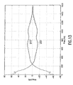
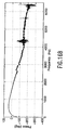
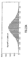
- Figure 12 shows the frequency response measurement of a KittyHawk II disk drive. Closed loop, open loop, and sensitivity functions are shown.
- Figure 13 shows the squared the magnitude of S and 1 / S .
- Figure 14 shows the PSD of PES as measured and when filtered by 1 /
- Bode's Integral Theorem The point of Bode's Integral Theorem is that the noise amplification will always be there. Servo engineers cannot eliminate it, they can only choose, through careful control design, where to put it. This is true in both continuous time control and discrete time control. There is the added nuisance of the Nyquist Rate "retaining wall” in discrete time. The "peaking" of PES at high frequency is not some anomaly of a poor control design. It is a natural consequence of doing control. Thus, if we are really going to be concerned with noise at high frequency, we should look at the sensitivity function, S, to see how our control design changes it. A control design methodology that takes this into account, such as QFT can be used.
- certain frequency response functions can either be generated from a model or measured in the laboratory.
- the following building blocks can either be obtained from laboratory measurements or models and used to construct any of the necessary filters. Because we are filtering PSDs, that the operation will involve the magnitude squared of the filter response.
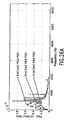
- obtaining open loop frequency response function measurements on a closed loop system can be done in one of two ways.
- the first, a 3-wire measurement involves injecting a signal at one point in the loop and reading the output at two other points in the loop. This allows for the direct measurement of open loop quantities from a closed loop system, but does a poor job of eliminating noise from the measured response.
- a closed loop measurement as shown in Figure 15, is made by allowing the first of the loop measurement points to be the injected signal. In order to obtain open loop quantities from such a measurement, the loop must be mathematically opened. This does a much better job of decorrelating noise in the loop from the desired frequency response function.
- Filter forwards from the noise source input to PES to obtain the effect of this noise on the PES PSD.
- the Pareto Method constructs, from measurements or design models, component filters and output power spectra;- these filters and spectra are then used to compute input noise spectra. The noise spectra are then fed individually through the closed loop model to determine their individual contribution to PES uncertainty.
- Figure 1 illustrates the disk drive track-follow servo system, including the measurement points (shown in bold font) which are available for gathering the required data. These measurement points are (1) PES, the servo demodulator output; (2) X in , a loop stimulus point; (3) X out , the command current into the actuator power amplifier; (4) I sense , a measurement of actuator coil current; and (5) LDV velocity, measuring the head's radial movement (LDV position was also available, but is better suited in this case for low-frequency measurements--i.e., below 20 Hz). The LDV's velocity output was integrated to obtain displacement information.
- PES the servo demodulator output
- X in a loop stimulus point
- X out the command current into the actuator power amplifier
- I sense a measurement of actuator coil current
- LDV velocity measuring the head's radial movement
- FFF frequency response function
- PSD power spectral density
- the primary measurement toolset included a laser Doppler Vibrometer (LDV, from Polytec), a 5-channel digital signal analyzer (HP 3567A), a digital storage oscilloscope (HP 54720D), and Matlab software running on a workstation.
- LDV laser Doppler Vibrometer
- HP 3567A 5-channel digital signal analyzer
- HP 54720D digital storage oscilloscope
- Matlab software running on a workstation.
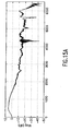
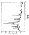
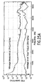
- Figure 15 illustrates the closed loop transfer function which was obtained by measuring the swept-sine response, X out / X in . (The spike near 4400 Hz indicates the Nyquist frequency.) The open loop transfer function can then be calculated from the closed loop measurement.
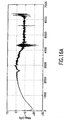
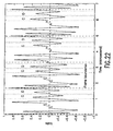
- the compensator transfer function, X out / PES is shown in Figure 16, and the "mechanics" transfer function, LDV / Torque (where Torque has been calculated by multiplying I sense by K t ), is shown in Figure 17.
- Power Spectra The following power spectra were obtained from each of the measurement points illustrated in Figure 1, with system parameters being varied in order to assess the system's sensitivity to each noise source. We present these power spectra in the order suggested by the system diagram, beginning with PES and ending with estimates of Position Sensing Noise (PSN). The analysis of PSN is presented last, because it relies on a different type of measurement and analysis than the other noises.
- PSN Position Sensing Noise
- DAC and ADC Resolution One suggested source of PES uncertainty is the finite resolution of the digital-to-analog (DAC) and analog-to-digital (ADC) converters on either side of the compensator. The starting point for determining this uncertainty was to successively mask off bits of each converter and observe changes in the PES power spectrum. This was accomplished by using a bandwidth of 2000 Hz rather than the 6400 Hz bandwidth (which we used in other measurements).
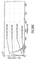
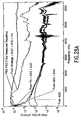
- Figure 18 illustrates the sensitivity of PES to DAC resolution
- Figure 19 shows the comparatively smaller effect of reducing ADC resolution. Note: As mentioned earlier, we concentrated on the PES baseline; hence, sharp spectral lines due to synchronous sources and bearing cage orders have been eliminated. These spectra were later subtracted from each other in order to isolate quantization noise.
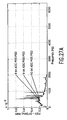
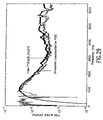
- Figure 20 illustrates the effect of loop gain on the spectra of PES and radial slider displacement.
- PES and LDV velocity were measured with (1) standard loop gain, (2) loop gain programmatically set to zero, and (3) the actuator physically disconnected from the servo system.
- the presence of a LDV setup resonance . (approximately 700 Hz) and the known disk resonances (500-1200 Hz (see, J.S.
- McAllister "The Effect of Disk Platter Resonances on Track Misregistration in 3.5 Inch Disk Drives," IEEE Transactions on Magnetics, vol.32, pp.1762-1766, May 1996) required further smoothing of this data when performing the PES decomposition.
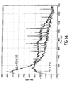
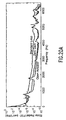
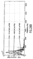
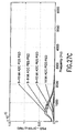
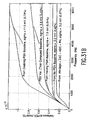
- Figure 21 is a series of radial slider displacement power spectra which were obtained at different rotational speeds ranging from 3600 to 9600 RPM with the loop open. Again, the 700 Hz LDV setup resonance is shown (and eventually removed from the data). A series of flexure resonances are also shown between 5-6 kHz.
- Position Sensing Noise This represents the error resulting from the process of magnetically sensing and then demodulating position information as a function of the servowritten reference and the location of the head relative to this reference.
- the basic idea is to conduct a statistical two-way analysis of variance (ANOVA, see, R.E. Walpole and R.H. Myers, Probability and Statistics for Engineers and Engineers, New York, NY, Macmillan, second ed., 1972) on the demodulated servo signal in order to provide an estimate of PSN.
- ANOVA Modeling Assumptions The purpose of using the ANOVA method is to partition statistical variations in data between meaningful sources--in this case, between error due to actual displacement and error due to PSN.
- ANOVA ANOVA Modeling Assumptions: The purpose of using the ANOVA method is to partition statistical variations in data between meaningful sources--in this case, between error due to actual displacement and error due to PSN.
- Samples of size n are selected from each of k populations (each sample is from the same servo burst, observed at k different times).
- the natural value of n is the number of servo bits within a given sector, for the continuous-servo case, the number chosen is somewhat arbitrary-short enough to insure the zero-displacement assumption described above but long enough to provide statistically significant variability.
- Values for each ensemble of n bits result from different treatments, which are not under our direct control, but rather, applied by the servo system as it attempts to follow track center. Treatments and measurement error are both assumed to be random and mutually independent.
- Equation 9 the right-side components of Equation 9 are ⁇ , the mean value of PES; ⁇ i , the effect due to random displacement error (the "treatment"); and E i j , the effect due to measurement error. Both ⁇ i and E ij are assumed to be normally distributed around a zero mean. The variance of ⁇ i is ⁇ 2 ⁇ , and the variance of E ij is ⁇ 2 Y .
- the variance of PSN, ⁇ 2 s depends on how the individual servo bits are processed, which is different for sectored- and continuous-servo cases.
- ⁇ 2 is computed in the following manner:
- the resultant ⁇ 2 s of Z ( t ) is an estimate of PSN.
- Test Setup and Data Processing The servo signals were accessed by connecting a HP 54720D digital oscilloscope to drive electronics via a Tektronix P6046 differential probe in order to improve common mode-noise rejection. Data acquisition was triggered using the drive's once-around index pulse. The number of instantaneous runs taken was 32 (each having 3278 data points). An ASCII file was produced for each of the 32 runs and transferred to the Matlab environment to compute the peak-detect C- and D-bit values for each set of 18 servo frames. The result was an 18-by-32 array of values for ANOVA use.
- Measurement Summary The measurements described above are accomplished by connecting to test points which are typically available for all disk drive products in the normal development process. The idea is to isolate each component of the servo system by making measurements on either side--where possible--or, as the case for Position Sensing Noise, collect data and analyze it under a set of reasonable assumptions (i.e., white noise). With this data in hand, it is possible to complete the third step in the Pareto method, namely, determining the effects of individual noise contributors on PES. Thus, the collection of required data is accomplished in a fairly straightforward manner, assuming care is taken to take sufficient, high-quality measurements.
- the Strata of the PES as Composed of Noise Source PSDs The preceding description has shown a method for separating the contributors of various sources of uncertainty "noises") in the position error signal (PES) of the track-follow servo in a disk drive and how specific measurements are made to isolate individual noise sources and to create appropriate filters from which the noises can be examined at their source and at PES. This section completes the process by using the method and the measurements to feed the appropriate spectra through the appropriate loop filters to yield both the input noise spectra and their effect - both individually and cumulatively - on PES. The PSDs are then integrated in frequency to yield the corresponding power spectra and variances.
- This section applies this method to a set of noise source isolation measurements described above to finally uncover the relative significance to PES of each noise source.
- This portion has the following organization. A first subsection goes through each individual measured noise source both at the source and at PES. A second subsection puts these together at PES. A third subsection then shows a small subset of what can be extrapolated from these results. Some conclusions are presented in a final subsection.
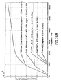
- Power Amplifier The power amplifier noise is measured directly at I sense . This measurement is made with the loop open, so no loop unwrapping is necessary. Furthermore, the power amplifier noise is modeled to enter the system right in front of I sense . Thus, the backwards filter to the source is simply unity (1) and the forward filter from the source noise PSD to PES PSD is ⁇ K t P ( s ) D ( s ) 1 + K t P ( s ) D ( s ) C ( s ) A ( s ) ⁇ 2 . Note from Figure 24 that power amp noise is only significant at low frequency.
- Windage is measured using the Laser Doppler Vibrometer (LDV) to measure the velocity of the readback head and then integrate it in time for the head position. (For frequencies above 10 Hz, this is considered more accurate than using a direct position measurement scheme.)
- LDV Laser Doppler Vibrometer
- the Windage is the difference between the head motion when the drive actuator is electrically disconnected from the power amp but the disk is spinning and the same measurement when the disk is stopped. In the former case, it can take several iterations to find a spot where the head will sit comfortably in order to make a reasonable measurement.
- the filter back to the source is given by ⁇ 1 P ( s ) ⁇ 2
- the filter forward from the source to PES is ⁇ P ( s ) D ( s ) 1 + K t P ( s ) D ( s ) C ( s ) A ( s ) ⁇ 2 .
- the effect of Windage as shown in Figure 25 is most significant below 1 kHz.
- the PES noise generated by the Lynx II's 10 bit DAC is derived in this way and shown in the bottom plot of Figure 26.
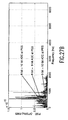
- the PES noise generated by the Lynx II's 10 bit ADC is derived in this way and shown in the bottom plot of Figure 27. Note that its effect on PES is even lower than that of the DAC.
- the first effort is to carefully study the wind flow within a disk drive to find ways to minimize the level of Windage noise. This is a nontrivial task involving the study of turbulent air flows (see, H. Suzuki and J.A.C. Humphrey, "Flow past Large Obstructions Between Corotating Disks in Fixed Cylindrical Enclosures," in Proceedings of the ASME IMECE Conference, Atlanta, GA, ASME, August 1996).
- the second effort is to find ways to minimize PSN. This can be accomplished via improving the readback process or the demodulation process (or both). Research is currently being done on the latter (see, A.H.
- the invention is not limited to the analysis of magnetic disk drives. It can be readily applied to the analysis of position error signals in optical disk drives and tape drives, as well as any other moving storage medium or servo loop.
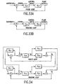
- FIG 33 A simplified view of focus and tracking loops as they are typically analyzed in the current art is shown in Figure 33.
- the focus and fine tracking systems are seen as decoupled.
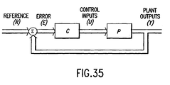
- the focus and fine tracking loops are coupled as shown in Figure 34. If this coupling were strong, then it would be necessary to use a multivariable approach as shown in Figure 35, where the thick lines depict a vector of signals and the system model is a multi-input, multi-output object.
- the block diagram in Figure 36 will serve as the map for our tour of noises in the system 200.
- the reference position that the focus actuator must follow is the vertical position 210 of the optical surface of the disk, turning on a spindle.
- Only the focus error -- the difference between the nominal focus point and the measured focus point are available. This is detected using one of several available Focus Error Detection 220 methods, each of which has its own level of Focus Sensing Noise and susceptibility to crosstalk from TES, groove distortion, and disk thickness.
- the detected FES signal is then sampled and converted to a digital format via an analog to digital converter 230 (ADC), filtered by the compensator 240 and then sent back out to the power amplifier 260 via a digital to analog converter 250 (DAC).
- ADC analog to digital converter
- DAC digital to analog converter 250
- the power amp 260 converts the desired voltage into a current to drive the voice coil actuator for the focus motor (with torque constant K F,t ).
- the actuator itself is subject to coupling from the torque applied to maintain track position and to nonlinear behaviors.
- the nominal dynamics of the actuator are encompassed in the Focus Actuator block 270 and the position of this actuator relative to the disk position is what determines the true focus error. The reading of this error is subject to distortions caused by disk thickness variations, groove distortions, and Focus Sensing Noise.
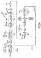
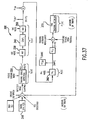
- the block diagram in Figure 37 will serve as the map for our tour of noises in the system 300.
- the reference position that the tracking actuator must follow is the radial position 310 of the data track at the recording surface of the disk, turning on a spindle. Only the tracking error - the difference between the nominal track center point and the measured tracking point is available. This is detected using one of several available Tracking Error Detection 320 methods, each of which has its own level of Track Sensing Noise and susceptibility to crosstalk from FES, groove distortion, and disk tilt.
- the detected TES signal is then sampled and converted to a digital format via an analog to digital converter 330 (ADC), filtered by the compensator 340 and then sent back out to the power amplifier 360 via a digital to analog converter 350 (DAC).
- ADC analog to digital converter
- DAC digital to analog converter 350
- the power amp 360 converts the desired voltage into a current to drive the voice coil actuator for the focus motor (with torque constant K T,t ).
- the actuator itself is subject to coupling from the torque applied to maintain track position and to nonlinear behaviors.
- the nominal dynamics of the actuator are encompassed in the Fine Tracking Actuator block 370 and the position of this actuator relative to the track center on the disk is what determines the true tracking error.
- the reading of this error is subject to distortions caused by disk tilt variations, groove distortions, and Track Sensing Noise.
- the method allows for the building of better storage devices by systematically categorizing the sources and effects of broadband noise. To recap, this method does so by allowing for several possibilities:
- the method allows the user to identify and rank the most critical noise sources in the positioning mechanism of a drive. This allows for optimization of the drive positioning control loop(s) by suitable design choices. Such choices may include -- but are not limited to -- optimization of the position encoding on the data storage surface (such as groove dimensions in an optical drive), optimization of the position signal detection method (such as the demodulation method on a magnetic disk or tape drive), and optimization of the actuator design. Such optimization is far more difficult without this invention as it is more difficult to identify which optimizations are most helpful.
- the method has been described as looking at the cumulative sums of PSDs at the PES signal (for magnetic drives) or FES and TES signals (for optical drives). However, it is not limited to such. In fact any signal point in the loop can be used for such purposes.
- PSDs Power Spectral Densities
Landscapes
- Engineering & Computer Science (AREA)
- Signal Processing (AREA)
- Feedback Control In General (AREA)
- Optical Recording Or Reproduction (AREA)
- Moving Of The Head To Find And Align With The Track (AREA)
- Signal Processing For Digital Recording And Reproducing (AREA)
Applications Claiming Priority (2)
| Application Number | Priority Date | Filing Date | Title |
|---|---|---|---|
| US866367 | 1997-05-30 | ||
| US08/866,367 US5909661A (en) | 1997-05-30 | 1997-05-30 | Method and apparatus for decomposing drive error signal noise sources |
Publications (2)
| Publication Number | Publication Date |
|---|---|
| EP0881626A1 EP0881626A1 (en) | 1998-12-02 |
| EP0881626B1 true EP0881626B1 (en) | 2003-09-24 |
Family
ID=25347459
Family Applications (1)
| Application Number | Title | Priority Date | Filing Date |
|---|---|---|---|
| EP98304213A Expired - Lifetime EP0881626B1 (en) | 1997-05-30 | 1998-05-28 | Noise measurement in data storage devices |
Country Status (4)
| Country | Link |
|---|---|
| US (1) | US5909661A (enExample) |
| EP (1) | EP0881626B1 (enExample) |
| JP (1) | JPH1172520A (enExample) |
| DE (1) | DE69818345T2 (enExample) |
Cited By (1)
| Publication number | Priority date | Publication date | Assignee | Title |
|---|---|---|---|---|
| US8937854B2 (en) | 2001-01-25 | 2015-01-20 | Optical Devices, Llc | Servo processor receiving photodetector signals |
Families Citing this family (42)
| Publication number | Priority date | Publication date | Assignee | Title |
|---|---|---|---|---|
| US6381088B1 (en) | 1998-11-06 | 2002-04-30 | Acorn Technologies, Inc. | Apparatus for developing a dynamic servo signal from data in a magnetic disc drive and method |
| USRE40413E1 (en) * | 1998-11-06 | 2008-07-01 | Purchased Patent Management Llc | Method and apparatus for developing a dynamic servo signal from data |
| US6417982B1 (en) * | 1998-12-02 | 2002-07-09 | International Business Machines Corporation | System and method for identifying and filtering a head suspension assembly resonance frequency |
| US6456450B1 (en) * | 1998-12-04 | 2002-09-24 | International Business Machines Corporation | Method and apparatus for reducing track misregistration due to digital-to-analog converter quantization noise |
| JP3552158B2 (ja) * | 1999-04-08 | 2004-08-11 | 富士通株式会社 | 記憶装置 |
| US6522495B1 (en) * | 1999-04-16 | 2003-02-18 | International Business Machines Corporation | System, method and program for determining the magnetic center shift within a disk drive system |
| US6618219B1 (en) | 1999-10-12 | 2003-09-09 | Seagate Technology Llc | Method and apparatus for feedforward cancellation using a peak detector |
| US6628472B1 (en) * | 1999-10-12 | 2003-09-30 | Seagate Technoogy Llc | Method and apparatus for feedforward cancellation using a phase lock loop |
| US6545836B1 (en) | 1999-11-12 | 2003-04-08 | Acorn Technologies, Inc. | Servo control apparatus and method using absolute value input signals |
| US6594103B1 (en) | 1999-11-12 | 2003-07-15 | Acorn Technologies, Inc. | Read channel generating absolute value servo signal |
| US6801387B1 (en) * | 2000-04-14 | 2004-10-05 | Seagate Technology Llc | Control flow instability to reduce disk flutter and half frequency whirl |
| SG104270A1 (en) * | 2000-06-14 | 2004-06-21 | Seagate Technology Llc | Feed-forward compensation of cage frequency using a reference head in a servo-writer |
| JP2004507024A (ja) | 2000-08-23 | 2004-03-04 | シーゲート テクノロジー リミテッド ライアビリティ カンパニー | Pes直線性に基づいてヘッドを高精度制御するためのトラック走査データを用いる方法と装置 |
| US6654198B2 (en) | 2000-08-23 | 2003-11-25 | Seagate Technology Llc | Repeatable run-out error compensation method for a disc drive |
| US6639753B1 (en) * | 2000-09-01 | 2003-10-28 | Hewlett-Packard Development Company, L.P. | Method of forming a head assembly, a head assembly, and a linear tape drive |
| JP4189119B2 (ja) * | 2000-09-21 | 2008-12-03 | 株式会社東芝 | ヘッド位置決め制御システム及び同システムを備えた磁気ディスク装置 |
| JP2002117636A (ja) * | 2000-10-03 | 2002-04-19 | Matsushita Electric Ind Co Ltd | 磁気ディスク装置の制御装置、方法、記録媒体及び磁気ディスク装置の検査方法、装置 |
| SG125068A1 (en) | 2001-09-11 | 2006-09-29 | Seagate Technology Llc | Method for sensing run-out in data fields |
| US7027251B1 (en) | 2002-01-04 | 2006-04-11 | Maxtor Corporation | Method and apparatus to control pole tip protrusion |
| US7224548B1 (en) * | 2002-01-04 | 2007-05-29 | Maxtor Corporation | Determining contact write current in disk drive using position error signal variance |
| US6895352B2 (en) * | 2002-03-12 | 2005-05-17 | Itt Manufacturing Enterprises, Inc. | Simultaneous rapid open and closed loop bode plot measurement using a binary pseudo-random sequence |
| US7023645B1 (en) | 2002-05-03 | 2006-04-04 | Maxtor Corporation | Read error recovery method and apparatus |
| US20030220751A1 (en) * | 2002-05-22 | 2003-11-27 | Toh Michael Joo Chiang | Method and apparatus to verify disc drive vibrational performance |
| US7035037B2 (en) * | 2002-06-18 | 2006-04-25 | Seagate Technology Llc | Disc drive with compensation for non-repeatable runout |
| US6782324B2 (en) * | 2002-08-16 | 2004-08-24 | Sun Microsystems, Inc. | Method and apparatus for using acoustic signals to identify one or more disc drives that are likely to fail |
| US7103426B2 (en) * | 2003-01-28 | 2006-09-05 | Rosemount Analytical Inc. | Anticipatory high frequency noise compensation in a distributed process control system |
| US7215623B2 (en) * | 2003-02-26 | 2007-05-08 | Matsushita Electric Industrial Co., Ltd. | Reproduction signal processing apparatus |
| US7050173B2 (en) * | 2003-04-01 | 2006-05-23 | Seagate Technology Llc | Method and arrangement for removing noise and measurements of head-media spacing modulation for digital recording |
| US7119986B2 (en) * | 2004-04-01 | 2006-10-10 | Seagate Technology Llc | Separator plate with head load/unload |
| EP1844466A2 (en) * | 2005-01-21 | 2007-10-17 | Koninklijke Philips Electronics N.V. | Disc drive apparatus with non-linear observer |
| US7328138B1 (en) * | 2005-07-21 | 2008-02-05 | Storage Technology Corporation | Method and system of measurement and optimization of noise in servo systems |
| US7865254B2 (en) * | 2007-01-11 | 2011-01-04 | The Mathworks, Inc. | Modeling of control systems with open-loop representations and factorization of components |
| US8086974B2 (en) * | 2008-03-31 | 2011-12-27 | International Business Machines Corporation | Structure for fractional-N phased-lock-loop (PLL) system |
| US7472362B1 (en) | 2008-03-31 | 2008-12-30 | International Business Machines Corporation | Method of minimizing phase noise |
| US7750697B2 (en) | 2008-03-31 | 2010-07-06 | International Business Machines Corporation | Fractional-N phased-lock-loop (PLL) system |
| US7926015B2 (en) * | 2008-03-31 | 2011-04-12 | International Business Machines Corporation | Optimization method for fractional-N phased-lock-loop (PLL) system |
| US9009455B2 (en) | 2011-05-03 | 2015-04-14 | Western Digital Technologies, Inc. | Booting from a secondary storage device in order to accumulate disk drive performance data |
| CN104614660B (zh) * | 2015-01-09 | 2017-04-26 | 中国电子科技集团公司第五十八研究所 | 基于有源光学水印的硬件木马检测方法 |
| US9460742B1 (en) | 2015-05-13 | 2016-10-04 | Seagate Technology Llc | Selecting servo controller based on predicted position error signal spectrum |
| US10672431B2 (en) | 2018-10-10 | 2020-06-02 | International Business Machines Corporation | Damping layers for mitigation of motor-induced disturbances applied to a tape reel |
| CN114268087B (zh) * | 2021-12-14 | 2023-12-01 | 北京航天测控技术有限公司 | 一种供电模块及供电方法 |
| CN119375643B (zh) * | 2024-12-30 | 2025-03-28 | 南京浦镇海通铁路设备有限公司 | 一种绝缘检测功能的检测方法及系统 |
Family Cites Families (3)
| Publication number | Priority date | Publication date | Assignee | Title |
|---|---|---|---|---|
| SU1277202A1 (ru) * | 1985-04-09 | 1986-12-15 | Войсковая часть 13991 | Устройство дл воспроизведени с носител магнитной записи |
| US5093751A (en) * | 1990-03-21 | 1992-03-03 | Hitachi Electronics Engineering Co., Ltd. | Carry noise measuring system for magnetic recording medium |
| US5663847A (en) * | 1995-03-27 | 1997-09-02 | Abramovitch; Daniel Y. | Rejection of disturbances on a disk drive by use of an accelerometer |
-
1997
- 1997-05-30 US US08/866,367 patent/US5909661A/en not_active Expired - Lifetime
-
1998
- 1998-05-28 JP JP10147474A patent/JPH1172520A/ja active Pending
- 1998-05-28 DE DE69818345T patent/DE69818345T2/de not_active Expired - Fee Related
- 1998-05-28 EP EP98304213A patent/EP0881626B1/en not_active Expired - Lifetime
Cited By (4)
| Publication number | Priority date | Publication date | Assignee | Title |
|---|---|---|---|---|
| US8937854B2 (en) | 2001-01-25 | 2015-01-20 | Optical Devices, Llc | Servo processor receiving photodetector signals |
| US9105281B2 (en) | 2001-01-25 | 2015-08-11 | Optical Devices, Llc | Servo processor receiving photodetector signals |
| US9245569B1 (en) | 2001-01-25 | 2016-01-26 | Optical Devices, Llc | Servo processor receiving photodetector signals |
| US9514777B2 (en) | 2001-01-25 | 2016-12-06 | Optical Devices, Llc | Servo processor receiving photodetector signals |
Also Published As
| Publication number | Publication date |
|---|---|
| US5909661A (en) | 1999-06-01 |
| JPH1172520A (ja) | 1999-03-16 |
| DE69818345T2 (de) | 2004-07-01 |
| EP0881626A1 (en) | 1998-12-02 |
| DE69818345D1 (de) | 2003-10-30 |
Similar Documents
| Publication | Publication Date | Title |
|---|---|---|
| EP0881626B1 (en) | Noise measurement in data storage devices | |
| Abramovitch et al. | An overview of the PES Pareto Method for decomposing baseline noise sources in hard disk position error signals | |
| JP2500100B2 (ja) | 位置誤差信号を生成するための装置、方法およびデ―タ記憶システム | |
| Vold et al. | High resolution order tracking at extreme slew rates, using Kalman tracking filters | |
| Jia | Disturbance rejection through disturbance observer with adaptive frequency estimation | |
| US6563663B1 (en) | Repeatable runout compensation using iterative learning control in a disc storage system | |
| Abramovitch et al. | The PES Pareto Method: Uncovering the strata of position error signals in disk drives | |
| JP2000505581A (ja) | サーボパターンエラーのドライブ内訂正 | |
| US6876168B1 (en) | Disturbance attenuation in a precision servomechanism by a frequency-separated acceleration soft sensor | |
| GB2134286A (en) | Apparatus for and method of random vibration control | |
| Abramovitch et al. | Decomposition of baseline noise sources in hard disk position error signals using the PES Pareto Method | |
| US20020012191A1 (en) | Repeated runout position error compensation in a disc drive servo system | |
| US20030133220A1 (en) | Written-in repeatable run-out compensation in embedded servo disc drives | |
| Ho | Noise impact on servo TMR | |
| Hurst et al. | Measurements for the PES Pareto Method of identifying contributors to disk drive servo system errors | |
| US8023392B2 (en) | Compensating the effects of non-synchronous writing of erasable servo marks | |
| US10839842B1 (en) | Attenuation of vibration-induced disturbances in a data storage device | |
| Nagashima et al. | Rejection of unknown periodic disturbances in magnetic hard disk drives | |
| Du et al. | Vibration analysis and control design comparison of HDDs using fluid bearing and ball bearing spindles | |
| US20030058569A1 (en) | Written-in repeatable run-out compensation in embedded servo disc drives | |
| US6456450B1 (en) | Method and apparatus for reducing track misregistration due to digital-to-analog converter quantization noise | |
| Guo et al. | A comprehensive time domain simulation tool for hard disk drive TPI prediction and mechanical/servo enhancement | |
| Sebastian et al. | Jitter investigation and performance evaluation of a small-scale probe storage device prototype | |
| HURST et al. | The PES Pareto Method: Uncovering the Strata of Position Error Signals in Disk Drives | |
| Ho et al. | Design and Analyses of HDD Servo System Using Power Spectrum Data |
Legal Events
| Date | Code | Title | Description |
|---|---|---|---|
| PUAI | Public reference made under article 153(3) epc to a published international application that has entered the european phase |
Free format text: ORIGINAL CODE: 0009012 |
|
| AK | Designated contracting states |
Kind code of ref document: A1 Designated state(s): DE FR GB |
|
| AX | Request for extension of the european patent |
Free format text: AL;LT;LV;MK;RO;SI |
|
| 17P | Request for examination filed |
Effective date: 19990601 |
|
| AKX | Designation fees paid |
Free format text: DE FR GB |
|
| RAP1 | Party data changed (applicant data changed or rights of an application transferred) |
Owner name: HEWLETT-PACKARD COMPANY, A DELAWARE CORPORATION |
|
| GRAH | Despatch of communication of intention to grant a patent |
Free format text: ORIGINAL CODE: EPIDOS IGRA |
|
| GRAS | Grant fee paid |
Free format text: ORIGINAL CODE: EPIDOSNIGR3 |
|
| GRAA | (expected) grant |
Free format text: ORIGINAL CODE: 0009210 |
|
| AK | Designated contracting states |
Kind code of ref document: B1 Designated state(s): DE FR GB |
|
| REG | Reference to a national code |
Ref country code: GB Ref legal event code: FG4D |
|
| REF | Corresponds to: |
Ref document number: 69818345 Country of ref document: DE Date of ref document: 20031030 Kind code of ref document: P |
|
| ET | Fr: translation filed | ||
| PLBE | No opposition filed within time limit |
Free format text: ORIGINAL CODE: 0009261 |
|
| STAA | Information on the status of an ep patent application or granted ep patent |
Free format text: STATUS: NO OPPOSITION FILED WITHIN TIME LIMIT |
|
| 26N | No opposition filed |
Effective date: 20040625 |
|
| PGFP | Annual fee paid to national office [announced via postgrant information from national office to epo] |
Ref country code: FR Payment date: 20090518 Year of fee payment: 12 Ref country code: DE Payment date: 20090528 Year of fee payment: 12 |
|
| PGFP | Annual fee paid to national office [announced via postgrant information from national office to epo] |
Ref country code: GB Payment date: 20100401 Year of fee payment: 13 |
|
| REG | Reference to a national code |
Ref country code: FR Ref legal event code: ST Effective date: 20110131 |
|
| PG25 | Lapsed in a contracting state [announced via postgrant information from national office to epo] |
Ref country code: DE Free format text: LAPSE BECAUSE OF NON-PAYMENT OF DUE FEES Effective date: 20101201 |
|
| PG25 | Lapsed in a contracting state [announced via postgrant information from national office to epo] |
Ref country code: FR Free format text: LAPSE BECAUSE OF NON-PAYMENT OF DUE FEES Effective date: 20100531 |
|
| GBPC | Gb: european patent ceased through non-payment of renewal fee |
Effective date: 20110528 |
|
| PG25 | Lapsed in a contracting state [announced via postgrant information from national office to epo] |
Ref country code: GB Free format text: LAPSE BECAUSE OF NON-PAYMENT OF DUE FEES Effective date: 20110528 |