EP0879748B1 - Kraftverstärker mit einem Dichtungsmechanismus - Google Patents
Kraftverstärker mit einem Dichtungsmechanismus Download PDFInfo
- Publication number
- EP0879748B1 EP0879748B1 EP98201315A EP98201315A EP0879748B1 EP 0879748 B1 EP0879748 B1 EP 0879748B1 EP 98201315 A EP98201315 A EP 98201315A EP 98201315 A EP98201315 A EP 98201315A EP 0879748 B1 EP0879748 B1 EP 0879748B1
- Authority
- EP
- European Patent Office
- Prior art keywords
- wall
- tube
- housing
- power booster
- axially extending
- Prior art date
- Legal status (The legal status is an assumption and is not a legal conclusion. Google has not performed a legal analysis and makes no representation as to the accuracy of the status listed.)
- Expired - Lifetime
Links
- 238000007789 sealing Methods 0.000 title description 10
- 230000004323 axial length Effects 0.000 description 10
- 230000000149 penetrating effect Effects 0.000 description 4
- 230000009977 dual effect Effects 0.000 description 3
- 230000000694 effects Effects 0.000 description 3
- 239000003562 lightweight material Substances 0.000 description 2
- 230000006978 adaptation Effects 0.000 description 1
- 230000015572 biosynthetic process Effects 0.000 description 1
- 238000010276 construction Methods 0.000 description 1
- 230000013011 mating Effects 0.000 description 1
- 239000002184 metal Substances 0.000 description 1
- 230000002093 peripheral effect Effects 0.000 description 1
- 239000004033 plastic Substances 0.000 description 1
- 239000012815 thermoplastic material Substances 0.000 description 1
Images

Classifications
-
- B—PERFORMING OPERATIONS; TRANSPORTING
- B60—VEHICLES IN GENERAL
- B60T—VEHICLE BRAKE CONTROL SYSTEMS OR PARTS THEREOF; BRAKE CONTROL SYSTEMS OR PARTS THEREOF, IN GENERAL; ARRANGEMENT OF BRAKING ELEMENTS ON VEHICLES IN GENERAL; PORTABLE DEVICES FOR PREVENTING UNWANTED MOVEMENT OF VEHICLES; VEHICLE MODIFICATIONS TO FACILITATE COOLING OF BRAKES
- B60T13/00—Transmitting braking action from initiating means to ultimate brake actuator with power assistance or drive; Brake systems incorporating such transmitting means, e.g. air-pressure brake systems
- B60T13/10—Transmitting braking action from initiating means to ultimate brake actuator with power assistance or drive; Brake systems incorporating such transmitting means, e.g. air-pressure brake systems with fluid assistance, drive, or release
- B60T13/24—Transmitting braking action from initiating means to ultimate brake actuator with power assistance or drive; Brake systems incorporating such transmitting means, e.g. air-pressure brake systems with fluid assistance, drive, or release the fluid being gaseous
- B60T13/46—Vacuum systems
- B60T13/52—Vacuum systems indirect, i.e. vacuum booster units
- B60T13/567—Vacuum systems indirect, i.e. vacuum booster units characterised by constructional features of the casing or by its strengthening or mounting arrangements
- B60T13/5675—Supportstruts
Definitions
- the invention relates to a power booster, according to the preamble of claim 1.
- Power boosters operating on a pressure differential are well known devices.
- a shell-like housing encloses at least one variable pressure chamber that is separated from a vacuum chamber by a diaphragm and its supporting wall.
- the diaphragm and supporting wall are axially moveable relative to the housing under variable pressure conditions.
- the housing's interior is subdivided by a housing divider wall separating a secondary variable pressure and vacuum chamber combination from the primary chamber pair.
- a power piston is urged to move axially by the diaphragm(s) and actuates an output rod for operating the vehicle brakes through an engaged master cylinder.
- a power booster can be reduced by using thin-wall or lightweight material for the housing walls.
- some additional structural support is obviously needed to maintain the structural integrity of the housing.
- One manner of providing the additional structural support is to extend a shaft or shafts through the housing to carry the generated loads, freeing the housing shell from this function. When axial forces are generated in the power booster, the shaft(s) hold the relative positions of the front and rear housing walls.
- the sealing structure preferably avoids adding to booster length while concurrently providing an effective seal between relatively movable components.
- the minimum theoretical length is equal to twice the space needed for the diaphragm and support wall travel distance, plus the thickness of the external housing walls, plus the divider wall thickness, plus the tolerances. In practice, approaching the minimum possible length has been difficult.
- the sealing mechanism undesirably adds to the booster length and may be difficult to assemble and expensive to produce. Accordingly, a new power booster sealing mechanism is needed.
- a power booster according to the preamble of claim 1 has been disclosed in for example the following documents:
- An aspect of the present invention resides in providing an improved sealing mechanism for power boosters, wherein the necessity of passing a component through the diaphragm(s) arises.
- a power booster directed at achieving this aspect includes a housing with a rear housing section and a front housing section that together, define an internal cavity.
- An internal housing wall separates the internal cavity into a first area and a second area with an opening formed in the internal housing wall, wherein it is desirable to extend a component through the opening.
- a tube has an end secured in the opening in the internal housing wall wherein the end includes a radially directed wall.
- the radially directed wall extends to an axially extending wall positioned concentrically with the tube's cylindrical body.
- the axially extending wall is positioned within the opening in the housing wall with a seal positioned between the axially extending wall and the housing wall. The distance between the front housing section and the rear housing section is advantageously minimized, with the component extending through the tube.
- a power booster is provided in a twin diaphragm arrangement.
- a housing divider wall separates the internal cavity into primary and secondary chambers, with an opening formed in the housing divider wall.
- the primary chamber includes a first vacuum compartment and a first variable pressure compartment wherein the first vacuum compartment and the first variable pressure compartment are separated by a first diaphragm.
- the secondary chamber includes a second vacuum compartment and a second variable pressure compartment wherein the second vacuum compartment and the second variable pressure compartment are separated by a second diaphragm. It is desirable to provide a continuously open communication route between the first and the second variable pressure compartments.
- a shaft extends through the opening in the housing divider wall.
- a tube is disposed about a portion of the shaft and has a first end secured in the opening in the housing divider wall and a second end positioned near the rear housing section so that the tube extends through the primary chamber penetrating the first diaphragm.
- the tube includes at least one opening near its second end, and its first end includes a radially directed wall that extends to an axially extending wall positioned concentrically with the tube.
- the axially extending wall is positioned within the opening in the housing divider wall with a seal positioned between the axially extending wall and the housing divider wall.
- the present invention may include a second end of the tube that is formed with a reduced cross section so that a flex zone is provided by the tube near the contact point between the tube and the rear housing section. This advantageously allows the length of the tube to adapt to the amount of free room, eliminating the need to provide clearance space which would undesirably add length to the power booster.
- the present invention is concerned with power boosters and is described in detail with reference to embodiments of power boosters with penetrating shafts that help support the power booster housing.
- the invention is also applicable to other situations without penetrating shafts such as when a subsidiary component of the power booster requires a passage through a diaphragm, its support wall, or a divider wall. Accordingly, the present description is only exemplary of the invention, which can be applied in a myriad of applications.
- a power booster's rear housing section 10 encloses a cavity 11 that contains a diaphragm 12 and its accompanying support wall 14.
- a housing divider wall 15 is positioned on the opposite side of the diaphragm 12 from the rear housing wall 10.
- a second diaphragm 16 and accompanying support wall 17 are positioned between the housing divider wall 15 and the front housing wall 18.
- a tube 19 extends through the housing divider wall 15, the diaphragm 12 and its support wall 14 and includes an end 20 that is engaged near the rear housing wall 10.
- the tube 19 provides an opening 21 through the diaphragm 12 and housing divider wall 15.
- a shaft 22 extends between the front housing wall 18 and the rear housing wall 10, and passes through the tube 19.
- the seal 23 is an axial length increasing component consuming several millimeters in the power booster's axial length L. This is demonstrated by the equation: L ⁇ T + SL + SE - I + ⁇ + K where:
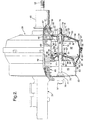
- power booster 30 is illustrated.
- the power booster 30 supports a master cylinder 31, which is commonly known in the art, and includes a push rod 32 that actuates the power booster 30 through a brake pedal (not illustrated).
- Power booster 30 is a dual diaphragm vacuum operated power booster in this exemplary embodiment.
- Power booster 30 has a substantially open internal cavity 35 which is formed by mating front housing section 33 and rear housing section 34.
- the front and rear housing sections 33 and 34 are formed from a conventional lightweight material such as metal or plastic.
- Rear housing section 34 includes an axially extending flange 36. Axially extending flange 36 mates with outer turned flange 37 of front housing section 33 locking the housing sections 33, 34 together.
- An inner edge 38 of rear housing section 34 carries a seal 39.
- the end of rear housing section 34 is enclosed by boot 40 which is received by the seal 39.
- a housing divider wall 41 separates the internal cavity 35 into primary and secondary chambers 42 and 43, respectively.
- Housing divider wall 41 includes an outer peripheral flange which is engaged between the front housing section 33 and rear housing section 34.
- Housing divider wall 41 also includes an inner edge 44 that carries an annular seal 45.
- a piston 48 extends through annular seal 45. The piston 48 is slidable forwardly and rearwardly to actuate the master cylinder 31 through the output rod 49.
- the annual seal 45 acts as a bearing for supporting the piston 48 in the lateral direction.
- Piston 48 is mechanically linked to a power piston 47 through a rubber reaction disk 46.
- This power piston 47 includes an annular wall 50, against which support wall 51 supports diaphragm 52.
- Diaphragm 52 includes an integral inner annular seal 53 which engages the power piston 47 and an integral outer annular seal 54 that engages housing divider wall 41 and the housing.
- Diaphragm 52 separates primary chamber 42 into variable pressure compartment 55 and vacuum compartment 56.
- Piston 48 includes annular wall 57 against which support wall 58 supports diaphragm 59.
- Diaphragm 59 includes an integral inner annular seal 60 which engages the piston 48 and an integral outer annular seal 61 that engages the housing divider wall 41 and the housing.
- Diaphragm 59 separates secondary chamber 43 into variable pressure compartment 62 and vacuum compartment 63.
- the diaphragms 52 and 59, and their respective support walls 51 and 58, are operable such that a vacuum pressure exists in vacuum compartments 56 and 63 which is generated therein by engine intake vacuum or by a supplementary source.
- a variable pressure exists in variable pressure compartments 55 and 62 for selectively moving power piston 47 and piston 48 forward in response to pressure differentials created by the introduction of atmospheric air through air valve 67.
- the variable pressure in variable pressure compartments 55 and 62 selectively creates a force on the respective diaphragms 52 and 59.
- the support walls 51 and 58 apply the force of the diaphragms 52,59 to the respective annular walls 50 and 57 of power piston 47 and piston 48.
- piston 48 compresses return spring 68, causing piston 48 to slide within annular seal 45 and power piston 47 to slide within seal 39, forcing output rod 49 to apply force to the master cylinder 31.
- variable pressure in variable pressure compartments 55 and 62 is increased through operation of the air valve 67.
- Air valve 67 selectively allows atmospheric pressure to enter the compartments 55 and 62 under operation of the pushrod 32 and thus creates a pressure differential across the diaphragms 52 and 59.
- the maximum pressure differential between the variable pressure compartments 55 and 62 on one hand, and vacuum compartments 56 and 63 on the other hand, is generally the difference between the vacuum source and atmospheric pressure.
- Atmospheric air entering the power booster 30 travels through the air valve 67 and the vacuum drawn from the power booster 30 exits through a vacuum check valve (not illustrated), which is received in the front housing section 33 in communication with vacuum chamber 63.
- Piston 48 includes an air passage 69 through which the vacuum effect is transferred from vacuum chamber 63 to vacuum chamber 56.
- a tube 70 is provided that extends from the housing divider wall 41 to near the rear wall 71 of rear housing section 34 where it is grounded to the housing.
- the tube 70 provides an opening 72 that extends through housing divider wall 41, diaphragm 52 and support wall 51.
- a series of side openings 73 are provided in tube 70 near tapered end 74 that register with the variable pressure compartment 55 so that the tube 70 provides the air flow path for atmospheric air entering the variable pressure compartment 62 from the variable pressure compartment 55.
- the tapered end 74 locates the tube 70 about a shaft 75.
- Shaft 75 extends through the power booster 30 and a flange 76 of master cylinder 31.
- the shaft 75 is fixed to the master cylinder 31 capturing the front wall 77 of front housing section 33 against the flange 76, and is held in place by a nut 97.
- the rear wall 71 is positioned by a flange 78 fixed in position on the shaft 75 and a segment 79 is provided for attachment to a vehicle's mounting structure (not illustrated).
- the shaft 75 extends through diaphragm 59 and its support wall 58, housing divider 41, and diaphragm 52 and its support wall 51.
- the support wall 51 includes an opening 80 with a forward turned lip 81, through which the shaft 75 extends.
- the diaphragm 52 includes an integral flexible sleeve 82 that extends through the opening 80 and engages tube 70, sealing thereagainst.
- the support wall 58 includes an opening 83 with a forward turned lip 84, through which the shaft 75 extends.
- the diaphragm 59 includes an integral flexible sleeve 85 that extends through the opening 83 and engages shaft 75, sealing thereagainst.
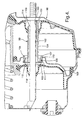
- the housing divider wall 41 includes an opening 86 that carries a seal 87.
- the seal 87 is of an annular dual lip construction.
- the tube 70 includes an end 88 that is secured in the opening 86 engaging the dual lips of the seal 87.
- a radially directed wall 90 extends to an axially extending wall 91 that is concentrically positioned about main cylindrical body 89.
- the axially extending wall 91 includes a radially outwardly turned lip 92, and the seal 87 engages the tube 70 at axially extending wall 91.
- the axially extending wall 91 is projected radially outside the sleeve 82 so that during maximum travel of the diaphragm 52 and its support wall 51, the sleeve 82 is received within annular pocket 93 maximizing travel and therefore, minimizing the overall axial length of the power booster 30. As shown in Figure 3, receipt of the sleeve 82 within pocket 93 substantially offsets any additional axial length of the seal 87 in the overall axial length of the power booster 30.
- the housing divider wall is subjected to a pressure differential between its side in variable pressure compartment 62 and its side in vacuum compartment 56.
- the pressure differential is equal to the difference between the vacuum source and the atmospheric pressure.
- this pressure differential may deflect the housing divider wall 41 an appreciable amount. Due to a range of tolerances in manufactured components, a clearance is optionally provided in the space 94 between the seal 87 and the outwardly turned lip 92. This is because the force effecting housing divider wall movement caused by the pressure differential may damage the tube 70 if restrained.
- the tube 70 includes a spring effect, wherein the tapered section 96 is elastically deformable and flexes to avoid the build-up of undue stresses.
- the adaptation of the tapered section 96 by formation of the openings 73 allows the length of the tube 70 to adapt to the movement of the housing divider wall 41 toward the rear wall 71 as permitted by flexure of the reduced cross sectional area of the tube 70 at the openings 73.
- the tube 70 is preferably made of a thermoplastic material.
- the power booster 98 is similar to the power booster 30 of Figure 2.
- the tube 99 includes an internal rib 100 near tapered end 101 that advantageously serves to locate the tube 99 on the shaft 102 in a substantially centered position.
- a notch 103 forms an opening to the interior of tube 99.
- the tube 99 also includes a main cylindrical body 104, and a radially directed wall 105 that extends to an axially extending wall 106 that is concentrically positioned about main cylindrical body 104.
- the axially extending wall 106 includes a radially outwardly turned lip 107.
- An annular groove 108 is formed around the axially extending wall 106.
- the housing divider wall 109 includes an opening 110 formed by forwardly turned annular wall 111.
- the forwardly tuned annular wall 111 is disposed about the axially extending wall 106 and its length covers a majority of the length of axially extending wall 106.
- a seal is carried in the annular groove 108 and bears against the forwardly turned annular wall 111 and axially extending wall 106.
- a clearance 112 is provided between the housing divider wall 109 and the outwardly turned lip 107 for axial movement caused by the variable pressure differentials across the housing divider wall 109.
- a set of four ribs 114 are integrally formed by the diaphragms at the sleeves that engage tube 99.
- a power booster sealing mechanism is provided that enables minimizing the overall axial length.
- the sealing mechanism is manufactured and assembled with relative ease.
Landscapes
- Engineering & Computer Science (AREA)
- Transportation (AREA)
- Mechanical Engineering (AREA)
- Braking Systems And Boosters (AREA)
Claims (7)
- Bremskraftverstärker mit:dadurch gekennzeichnet, dass sich die sich radial erstreckende Wand zu einer sich axial erstreckenden Wand (91) erstreckt, die allgemein konzentrisch mit dem Körper positioniert ist, wobei die sich axial erstreckende Wand in der Öffnung in der Gehäusewand mit einer Dichtung (87) positioniert ist, die zwischen der sich axial erstreckenden Wand und der Gehäusewand positioniert ist, wobei die Distanz zwischen dem vorderen Gehäuseabschnitt und dem rückwärtigen Gehäuseabschnitt an einer Achse, die sich durch die Komponente erstreckt, minimiert ist.einem Gehäuse mit einem rückwärtigen Gehäuseabschnitt (34) undeinem vorderen Gehäuseabschnitt (33), die einen inneren Hohlraum (35) definieren;einer Gehäusewand (41), die den inneren Hohlraum in einen ersten Bereich (42) und einen zweiten Bereich (43) trennt, wobei eine Öffnung (86) in der Gehäusewand ausgebildet ist, wobei es erwünscht ist, dass sich eine Komponente (75) durch die Öffnung erstreckt; einem Rohr (70), das einen Körper mit einem Ende (88) aufweist, das in der Öffnung in der Gehäusewand befestigt ist, wobei das Ende eine radial gerichtete Wand (90) umfasst, die sich von dem Ende des Rohres erstreckt,
- Bremskraftverstärker nach Anspruch 1,
ferner mit einer Membran (52), die in dem Hohlraum positioniert ist,
wobei die Membran eine Hülse (82) umfasst, die einstückig mit der Membran ausgebildet ist, wobei die Hülse abdichtend mit dem Rohr in Eingriff steht und entlang des Rohres mit einer Bewegung der Membran verschiebbar ist, wobei, wenn der Bremskraftverstärker betätigt ist, die Hülse zu einer Stellung zwischen dem Körper und der sich axial erstreckenden Wand des Rohres mit einer ringförmigen Tasche (93) verschiebbar ist. - Bremskraftverstärker nach Anspruch 2,
wobei das Rohr ein verjüngtes Ende (74) umfasst, das in der Nähe des rückwärtigen Gehäuseabschnittes mit zumindest einer Seitenöffnung (73) in der Nähe des verjüngten Endes positioniert ist, so dass der erste Bereich zu dem zweiten Bereich durch die Seitenöffnung und das Rohr offen ist. - Bremskraftverstärker nach Anspruch 3,
wobei das Rohr eine auswärts gebogene Lippe (92) umfasst, die sich von der sich axial erstreckenden Wand erstreckt, um als ein Anschlag zwischen der Gehäusewand und dem Rohr zu dienen. - Bremskraftverstärker nach Anspruch 4,
wobei die Gehäusewand eine Kraft an das Rohr während einer Betätigung des Bremskraftverstärkers anlegt, und wobei sich in Ansprechen darauf das Rohr in der Nähe des verjüngten Endes biegt. - Bremskraftverstärker nach Anspruch 5,
wobei die Gehäusewand eine gebogene ringförmige Wand (111) umfasst, die um die sich axial erstreckende Wand des Rohres angeordnet ist, wobei eine ringförmige Dichtung zwischen der sich axial erstreckenden Wand und der gebogenen ringförmigen Wand angeordnet ist. - Bremskraftverstärker nach Anspruch 6,
wobei die sich axial erstreckende Wand eine ringförmige Nut (108) umfasst, die die ringförmige Dichtung aufnimmt.
Applications Claiming Priority (2)
| Application Number | Priority Date | Filing Date | Title |
|---|---|---|---|
| US859932 | 1986-05-05 | ||
| US08/859,932 US5878650A (en) | 1997-05-21 | 1997-05-21 | Power booster sealing mechanism |
Publications (3)
| Publication Number | Publication Date |
|---|---|
| EP0879748A2 EP0879748A2 (de) | 1998-11-25 |
| EP0879748A3 EP0879748A3 (de) | 1998-12-23 |
| EP0879748B1 true EP0879748B1 (de) | 2002-07-10 |
Family
ID=25332092
Family Applications (1)
| Application Number | Title | Priority Date | Filing Date |
|---|---|---|---|
| EP98201315A Expired - Lifetime EP0879748B1 (de) | 1997-05-21 | 1998-04-23 | Kraftverstärker mit einem Dichtungsmechanismus |
Country Status (3)
| Country | Link |
|---|---|
| US (1) | US5878650A (de) |
| EP (1) | EP0879748B1 (de) |
| DE (1) | DE69806446T2 (de) |
Families Citing this family (15)
| Publication number | Priority date | Publication date | Assignee | Title |
|---|---|---|---|---|
| GB2332253B (en) * | 1997-12-10 | 2002-03-20 | Delphi France Automotive Sys | A brake booster |
| FR2777850B1 (fr) | 1998-04-24 | 2000-06-09 | Bosch Syst Freinage | Dispositif de freinage a entretoise simplifiee |
| DE10136379C1 (de) * | 2001-07-26 | 2002-12-05 | Lucas Automotive Gmbh | Unterdruckbremskraftverstärker mit vereinfachter Montage |
| US6719477B2 (en) | 2001-11-02 | 2004-04-13 | Delphi Technologies, Inc. | Spacer for vacuum brake booster |
| US6588317B2 (en) * | 2001-11-09 | 2003-07-08 | Delphi Technologies, Inc. | Power booster sealing mechanism |
| US6755117B2 (en) * | 2001-11-09 | 2004-06-29 | Delphi Technologies, Inc. | Tandem vacuum booster assembly including sleeve for air transfer between high pressure chambers |
| US20030209139A1 (en) * | 2002-05-07 | 2003-11-13 | Delphi Technologies Inc. | Tandem vacuum booster with extensible bellow air sleeve |
| US6758041B2 (en) * | 2002-09-12 | 2004-07-06 | Delphi Technologies, Inc. | Electric power brake booster |
| US20040134295A1 (en) * | 2003-01-13 | 2004-07-15 | Delphi Technologies Inc. | Engine compartment breather boot |
| DE10359176A1 (de) * | 2003-05-14 | 2004-12-09 | Continental Teves Ag & Co. Ohg | Pneumatischer Bremskraftverstärker |
| US20050039597A1 (en) * | 2003-08-19 | 2005-02-24 | Delphi Technologies Inc. | Modular valve assembly for a vacuum booster |
| FR2882316B1 (fr) * | 2005-02-18 | 2007-04-20 | Bosch Gmbh Robert | Tirant pour servomoteur d'assistance au freinage d'un vehicule et servomoteur appliquant un tel tirant |
| DE102009037232A1 (de) * | 2008-09-26 | 2010-04-01 | Continental Teves Ag & Co. Ohg | Pneumatischer Bremskraftverstärker |
| ES2483597B1 (es) * | 2013-02-06 | 2015-05-11 | Robert Bosch Gmbh | Servomotor neumático tándem de asistencia a la frenada |
| CN110949346A (zh) * | 2019-12-23 | 2020-04-03 | 吉林东光奥威汽车制动系统有限公司 | 具有通气结构的11+11英寸贯穿式双膜片真空助力器总成 |
Family Cites Families (28)
| Publication number | Priority date | Publication date | Assignee | Title |
|---|---|---|---|---|
| US3388635A (en) * | 1966-05-02 | 1968-06-18 | Bendix Corp | Fluid pressure motor |
| US4270353A (en) * | 1977-10-20 | 1981-06-02 | Girling Limited | Servo boosters for vehicle brake systems |
| GB2022207B (en) * | 1978-05-20 | 1982-07-14 | Girling Ltd | Servo boosters for vehivle braking systems |
| FR2432412B2 (fr) * | 1978-05-20 | 1985-09-27 | Girling Ltd | Amplificateur de servo-commande pour systemes de freinage de vehicules |
| ZA793139B (en) * | 1978-07-08 | 1980-06-25 | Lucas Industries Ltd | Servo boosters for vehicle braking systems |
| ZA793137B (en) * | 1978-07-08 | 1980-06-25 | Lucas Industries Ltd | Servo boosters for vehicle braking systems |
| DE2830262A1 (de) * | 1978-07-10 | 1980-01-24 | Teves Gmbh Alfred | Bremskraftverstaerker fuer ein kraftfahrzeug |
| AU530317B2 (en) * | 1978-09-20 | 1983-07-14 | Tokico Ltd. | Vacuum booster for hydraulic brakes |
| DE2908515A1 (de) * | 1979-03-05 | 1980-10-09 | Teves Gmbh Alfred | Bremskraftverstaerker fuer ein kraftfahrzeug |
| DE2908516A1 (de) * | 1979-03-05 | 1980-10-16 | Teves Gmbh Alfred | Bremskraftverstaerker fuer ein kraftfahrzeug |
| DE2918914A1 (de) * | 1979-05-10 | 1980-12-11 | Teves Gmbh Alfred | Bremskraftverstaerker |
| DE3161726D1 (en) * | 1980-02-23 | 1984-02-02 | Lucas Ind Plc | Servo boosters for vehicle braking systems |
| JPS5945538B2 (ja) * | 1980-09-12 | 1984-11-07 | 日信工業株式会社 | 負圧式倍力装置 |
| JPS5945539B2 (ja) * | 1980-09-18 | 1984-11-07 | 日信工業株式会社 | 負圧式倍力装置 |
| JPS625967Y2 (de) * | 1980-09-19 | 1987-02-10 | ||
| JPS6030585B2 (ja) * | 1980-09-25 | 1985-07-17 | 日信工業株式会社 | 負圧式倍力装置 |
| JPS5758548A (en) * | 1980-09-26 | 1982-04-08 | Nissin Kogyo Kk | Pneumatic pressure type doubler device |
| GB2092251B (en) * | 1980-12-06 | 1985-02-06 | Nissin Kogyo Kk | Vacuum booster assembly |
| JPS609939B2 (ja) * | 1981-07-01 | 1985-03-14 | 日信工業株式会社 | 負圧式倍力装置 |
| JPS584661A (ja) * | 1981-07-01 | 1983-01-11 | Nissin Kogyo Kk | 負圧式倍力装置 |
| JPS59114151A (ja) * | 1982-12-20 | 1984-07-02 | Aisin Seiki Co Ltd | タンデム型ブレ−キ倍力装置 |
| JPS59120559A (ja) * | 1982-12-27 | 1984-07-12 | Aisin Seiki Co Ltd | タンデム型ブレ−キ倍力装置 |
| GB8726722D0 (en) * | 1987-11-14 | 1987-12-16 | Lucas Ind Plc | Brake servo booster |
| DE58904817D1 (de) * | 1988-02-05 | 1993-08-05 | Lucas Ind Plc | Pneumatischer kraftverstaerker in tandembauweise, insbesondere fuer hydraulische fahrzeug-bremsanlagen. |
| DE8810531U1 (de) * | 1988-08-19 | 1989-12-21 | Lucas Industries P.L.C., Birmingham, West Midlands | Bremsbetätigungs-Baugruppe für Kraftfahrzeuge |
| DE8908040U1 (de) * | 1989-06-30 | 1990-10-31 | Lucas Industries P.L.C., Birmingham, West Midlands | Ventilbaugruppe zum Steuern eines pneumatischen Bremskraftverstärkers |
| DE4202820C2 (de) * | 1992-01-31 | 1996-09-05 | Lucas Ind Plc | Betätigungseinheit für Kraftfahrzeugbremsen |
| GB9211850D0 (en) * | 1992-06-04 | 1992-07-15 | Lucas Ind Plc | Improvements in pneumatically operated boosters for vehicle braking systems |
-
1997
- 1997-05-21 US US08/859,932 patent/US5878650A/en not_active Expired - Lifetime
-
1998
- 1998-04-23 DE DE69806446T patent/DE69806446T2/de not_active Expired - Lifetime
- 1998-04-23 EP EP98201315A patent/EP0879748B1/de not_active Expired - Lifetime
Also Published As
| Publication number | Publication date |
|---|---|
| DE69806446D1 (de) | 2002-08-14 |
| DE69806446T2 (de) | 2002-11-07 |
| EP0879748A2 (de) | 1998-11-25 |
| EP0879748A3 (de) | 1998-12-23 |
| US5878650A (en) | 1999-03-09 |
Similar Documents
| Publication | Publication Date | Title |
|---|---|---|
| EP0879748B1 (de) | Kraftverstärker mit einem Dichtungsmechanismus | |
| US4590845A (en) | Pneumatic servo booster | |
| JPS5940660B2 (ja) | バキユ−ムブレ−キブ−スタ | |
| SK278488B6 (en) | The valve assembly for controlling pneumatic brake booster | |
| US4347779A (en) | Vacuum brake booster | |
| GB2100379A (en) | Pneumatic booster | |
| JPS5924021B2 (ja) | バキユ−ムブレ−キブ−スタ | |
| GB2060100A (en) | Vacuum brake boosters | |
| US4481865A (en) | Vacuum brake booster | |
| GB2132720A (en) | Tandem-piston brake power booster | |
| KR0177817B1 (ko) | 차량브레이크 시스템용 공압부우스터 | |
| US6588317B2 (en) | Power booster sealing mechanism | |
| US4402256A (en) | Pneumatic servo booster | |
| GB2069638A (en) | Master cylinder and servo booster assemblies for vehicle braking systems | |
| US4407184A (en) | Pneumatic servo booster | |
| US5680807A (en) | Vacuum brake booster for motor vehicles | |
| JPH0110291Y2 (de) | ||
| EP0035370A1 (de) | Pneumatischer Servo-Kraftverstärker | |
| US5115719A (en) | Pneumatic booster | |
| US5079991A (en) | Brake booster | |
| GB2070707A (en) | Vacuum brake booster | |
| US5570622A (en) | Power booster with guided power piston | |
| GB2072778A (en) | Brake booster | |
| US8661964B2 (en) | Vacuum-assisted brake-force booster for a motor-vehicle braking system | |
| US20050087067A1 (en) | Vacuum booster with self-locking diaphragm support |
Legal Events
| Date | Code | Title | Description |
|---|---|---|---|
| PUAI | Public reference made under article 153(3) epc to a published international application that has entered the european phase |
Free format text: ORIGINAL CODE: 0009012 |
|
| PUAL | Search report despatched |
Free format text: ORIGINAL CODE: 0009013 |
|
| AK | Designated contracting states |
Kind code of ref document: A2 Designated state(s): DE FR GB |
|
| AX | Request for extension of the european patent |
Free format text: AL;LT;LV;MK;RO;SI |
|
| AK | Designated contracting states |
Kind code of ref document: A3 Designated state(s): AT BE CH CY DE DK ES FI FR GB GR IE IT LI LU MC NL PT SE |
|
| AX | Request for extension of the european patent |
Free format text: AL;LT;LV;MK;RO;SI |
|
| 17P | Request for examination filed |
Effective date: 19990623 |
|
| AKX | Designation fees paid |
Free format text: DE FR GB |
|
| RAP1 | Party data changed (applicant data changed or rights of an application transferred) |
Owner name: DELPHI TECHNOLOGIES, INC. |
|
| GRAG | Despatch of communication of intention to grant |
Free format text: ORIGINAL CODE: EPIDOS AGRA |
|
| RTI1 | Title (correction) |
Free format text: POWER BOOSTER HAVING A SEALING MECHANISM |
|
| 17Q | First examination report despatched |
Effective date: 20010830 |
|
| GRAG | Despatch of communication of intention to grant |
Free format text: ORIGINAL CODE: EPIDOS AGRA |
|
| GRAH | Despatch of communication of intention to grant a patent |
Free format text: ORIGINAL CODE: EPIDOS IGRA |
|
| GRAG | Despatch of communication of intention to grant |
Free format text: ORIGINAL CODE: EPIDOS AGRA |
|
| GRAH | Despatch of communication of intention to grant a patent |
Free format text: ORIGINAL CODE: EPIDOS IGRA |
|
| GRAG | Despatch of communication of intention to grant |
Free format text: ORIGINAL CODE: EPIDOS AGRA |
|
| GRAH | Despatch of communication of intention to grant a patent |
Free format text: ORIGINAL CODE: EPIDOS IGRA |
|
| GRAH | Despatch of communication of intention to grant a patent |
Free format text: ORIGINAL CODE: EPIDOS IGRA |
|
| GRAA | (expected) grant |
Free format text: ORIGINAL CODE: 0009210 |
|
| AK | Designated contracting states |
Kind code of ref document: B1 Designated state(s): DE FR GB |
|
| REG | Reference to a national code |
Ref country code: GB Ref legal event code: FG4D |
|
| REF | Corresponds to: |
Ref document number: 69806446 Country of ref document: DE Date of ref document: 20020814 |
|
| ET | Fr: translation filed | ||
| PLBE | No opposition filed within time limit |
Free format text: ORIGINAL CODE: 0009261 |
|
| STAA | Information on the status of an ep patent application or granted ep patent |
Free format text: STATUS: NO OPPOSITION FILED WITHIN TIME LIMIT |
|
| 26N | No opposition filed |
Effective date: 20030411 |
|
| PGFP | Annual fee paid to national office [announced via postgrant information from national office to epo] |
Ref country code: GB Payment date: 20050418 Year of fee payment: 8 Ref country code: FR Payment date: 20050418 Year of fee payment: 8 |
|
| PG25 | Lapsed in a contracting state [announced via postgrant information from national office to epo] |
Ref country code: GB Free format text: LAPSE BECAUSE OF NON-PAYMENT OF DUE FEES Effective date: 20060423 |
|
| GBPC | Gb: european patent ceased through non-payment of renewal fee |
Effective date: 20060423 |
|
| REG | Reference to a national code |
Ref country code: FR Ref legal event code: ST Effective date: 20061230 |
|
| PG25 | Lapsed in a contracting state [announced via postgrant information from national office to epo] |
Ref country code: FR Free format text: LAPSE BECAUSE OF NON-PAYMENT OF DUE FEES Effective date: 20060502 |
|
| PGFP | Annual fee paid to national office [announced via postgrant information from national office to epo] |
Ref country code: DE Payment date: 20170420 Year of fee payment: 20 |
|
| REG | Reference to a national code |
Ref country code: DE Ref legal event code: R071 Ref document number: 69806446 Country of ref document: DE |