EP0879673A2 - Ein teilbarer Getriebekasten in einer Drehbank - Google Patents
Ein teilbarer Getriebekasten in einer Drehbank Download PDFInfo
- Publication number
- EP0879673A2 EP0879673A2 EP98500114A EP98500114A EP0879673A2 EP 0879673 A2 EP0879673 A2 EP 0879673A2 EP 98500114 A EP98500114 A EP 98500114A EP 98500114 A EP98500114 A EP 98500114A EP 0879673 A2 EP0879673 A2 EP 0879673A2
- Authority
- EP
- European Patent Office
- Prior art keywords
- gearbox
- casing
- shaft
- headstock
- lathe
- Prior art date
- Legal status (The legal status is an assumption and is not a legal conclusion. Google has not performed a legal analysis and makes no representation as to the accuracy of the status listed.)
- Granted
Links
- 238000003801 milling Methods 0.000 claims abstract description 5
- 230000005540 biological transmission Effects 0.000 description 7
- 230000008439 repair process Effects 0.000 description 7
- 238000012423 maintenance Methods 0.000 description 1
Images
Classifications
-
- B—PERFORMING OPERATIONS; TRANSPORTING
- B23—MACHINE TOOLS; METAL-WORKING NOT OTHERWISE PROVIDED FOR
- B23Q—DETAILS, COMPONENTS, OR ACCESSORIES FOR MACHINE TOOLS, e.g. ARRANGEMENTS FOR COPYING OR CONTROLLING; MACHINE TOOLS IN GENERAL CHARACTERISED BY THE CONSTRUCTION OF PARTICULAR DETAILS OR COMPONENTS; COMBINATIONS OR ASSOCIATIONS OF METAL-WORKING MACHINES, NOT DIRECTED TO A PARTICULAR RESULT
- B23Q5/00—Driving or feeding mechanisms; Control arrangements therefor
- B23Q5/02—Driving main working members
- B23Q5/04—Driving main working members rotary shafts, e.g. working-spindles
- B23Q5/043—Accessories for spindle drives
- B23Q5/048—Speed-changing devices
Definitions
- the present invention relates to a lathe or milling machine gearbox with a train of several successive shafts of gear wheels, part of which can be separated for removal from the machine.
- Known vertical lathes or milling machines with the work-piece headstock fixed to the machine bed have the gearbox gear train housed inside the front of the machine frame from which the headstock casing protrudes, fitted with a removable front cover for access to the interior of the headstock for repairs.
- the gear train in such known lathes comprises several gear shafts, including the shaft of the headstock working-spindle situated in the first position in relation to the front of the machine, and a shaft for change of speed, all of which are vertical and meshed in succession from front to back, under the frame.
- EP-517387 describes an adaptor for a rotating tool holder with part of the casing containing a transmission gear which can be separated from the headstock.
- the object of the invention is a gearbox which can be divided in two for lathes and milling machines, as defined in claim 1, including the gear train and the gearbox casing, one of the parts of which can be separated and removed for repairs to the gearbox.
- the shaft of the headstock spindle has a gear wheel coupled with a second transmission shaft and, for repairs, both shafts remain immobile inside the front half of the casing, of the headstock, since access to its components is easy through a front headstock cover.
- the drive shaft and gearbox shaft are located behind the headstock under the machine frame and it is not possible to access them without removing them.
- part of the casing can be separated from the part of the headstock casing and can be manually removed from the machine.
- the separable half of the gearbox incorporates devices for sliding it out of the machine with the aid of support elements on the machine bed, and the means to pivot it subsequently in order to provide a view of free access to the interior.
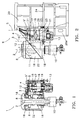
- FIGURE 1 is a transverse cross-section view of the gear box according to the invention.
- FIGURE 2 is a side elevation view of the lathe, with the gearbox in figure 1.
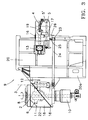
- FIGURE 3 is a side elevation view of the lathe in figure 2, showing part of the gearbox separated and taken out of the machine.
- the gearbox 1 shown in figure 1 is an embodiment of the invention, it has four shafts 2,3,4,5 of respective gear wheels 6,12,15,16 to transmit the rotation movement to the shaft of the headstock spindle 8 which is fixed to the vertical lathe shown in figures 2 and 3, and the chuck, not shown, is located at the top of the work-piece headstock, with the cylinder 10 to drive the grips at the bottom of the spindle 8.
- the first gear shaft 2 of the spindle is located inside the work-piece headstock on the front of the lathe and has a wheel 6 coupled which meshes with the second transmission shaft 3.
- the other shafts 3,4,5 of the gear train are located successively one after the other to the back of the lathe and, of these, the second shaft 3 is a transmission shaft with a pinion 12 to drive the shaft 2 of the spindle, while the third shaft 4, with two drive pinions 15, 16 for the transmission of different speeds, is the drive shaft moved by a pulley 13 and belt set, and the fourth shaft 5 belongs to a hydraulic cylinder 5' that drives a device 17 which makes the drive pinions 15, 16 slide to change gear.
- the shaft 2 of the spindle and the transmission shaft 3 are housed inside the half 18 of the casing of the gearbox 1 while the drive shaft 4 and shaft 5 of the gearbox are housed inside the rear half 19 of said gearbox.
- the two halves 18 and 19 of the gearbox 1 casing are coupled and joined by a set of bolts 21, the half casing 18 housing the headstock is fixed to the front 20 a of the lathe bed 20 and has a front cover 22 whose entrance provides access to gears 6 and 12 of the spindle and transmission shafts, while half-casing 19 of the two rear shafts 4 and 5 can be removed by releasing the bolts 21, being supported on two pairs of bearings 23 by means of which it slides toward the rear of the lathe along two slide guide-bars 24 supported on the bed 20.
- the casing 19 Once the casing 19 has been removed from the lathe, it is rotated one quarter turn on a pivot 25 linked to the rear bearings 23 by means of the pivoting arm 26, to reveal the gears 15, 16 of the drive shaft 4 and the
Landscapes
- Engineering & Computer Science (AREA)
- Mechanical Engineering (AREA)
- General Details Of Gearings (AREA)
- Turning (AREA)
Applications Claiming Priority (2)
| Application Number | Priority Date | Filing Date | Title |
|---|---|---|---|
| ES9701091A ES2151348B1 (es) | 1997-05-21 | 1997-05-21 | Caja de velocidad de torno divisible. |
| ES9701091 | 1997-05-21 |
Publications (3)
| Publication Number | Publication Date |
|---|---|
| EP0879673A2 true EP0879673A2 (de) | 1998-11-25 |
| EP0879673A3 EP0879673A3 (de) | 2000-07-05 |
| EP0879673B1 EP0879673B1 (de) | 2002-01-09 |
Family
ID=8299381
Family Applications (1)
| Application Number | Title | Priority Date | Filing Date |
|---|---|---|---|
| EP19980500114 Expired - Lifetime EP0879673B1 (de) | 1997-05-21 | 1998-05-08 | Ein teilbarer Getriebekasten in einer Drehbank |
Country Status (3)
| Country | Link |
|---|---|
| EP (1) | EP0879673B1 (de) |
| DE (1) | DE69803118T2 (de) |
| ES (1) | ES2151348B1 (de) |
Cited By (1)
| Publication number | Priority date | Publication date | Assignee | Title |
|---|---|---|---|---|
| CN113843625A (zh) * | 2021-09-29 | 2021-12-28 | 常州明迪机械有限公司 | 一种分体式齿轮箱加工装配工装及其装配方法 |
Citations (1)
| Publication number | Priority date | Publication date | Assignee | Title |
|---|---|---|---|---|
| EP0517387A2 (de) | 1991-05-20 | 1992-12-09 | Koyo Seiko Co., Ltd. | Fräsvorsatz |
Family Cites Families (5)
| Publication number | Priority date | Publication date | Assignee | Title |
|---|---|---|---|---|
| SU604633A1 (ru) * | 1976-12-01 | 1978-04-30 | Специальное Конструкторское Бюро Расточных Станков | Шпиндельна бабка металлорежущего станка |
| SU677823A2 (ru) * | 1978-02-07 | 1979-08-05 | Московское Специальное Конструкторское Бюро Автоматическх Линий И Агрегатных Станков | Шпиндельна коробка |
| JPS55125961A (en) * | 1979-03-20 | 1980-09-29 | Masao Obata | Device for feeding tool rest during rotation |
| DD204640A1 (de) * | 1981-12-28 | 1987-01-21 | Werkzeugmaschinenfabrik Union | Getriebe fuer die hauptspindel einer horizontalbohantrieb fuer die hauptspindel einer horizontalbohrr- und fraesmaschine - und fraesmaschine |
| DE3226105C2 (de) * | 1982-07-13 | 1985-02-21 | Fa. Alfred H. Schütte, 5000 Köln | Mehrspindeldrehautomat |
-
1997
- 1997-05-21 ES ES9701091A patent/ES2151348B1/es not_active Expired - Fee Related
-
1998
- 1998-05-08 DE DE1998603118 patent/DE69803118T2/de not_active Expired - Fee Related
- 1998-05-08 EP EP19980500114 patent/EP0879673B1/de not_active Expired - Lifetime
Patent Citations (1)
| Publication number | Priority date | Publication date | Assignee | Title |
|---|---|---|---|---|
| EP0517387A2 (de) | 1991-05-20 | 1992-12-09 | Koyo Seiko Co., Ltd. | Fräsvorsatz |
Cited By (2)
| Publication number | Priority date | Publication date | Assignee | Title |
|---|---|---|---|---|
| CN113843625A (zh) * | 2021-09-29 | 2021-12-28 | 常州明迪机械有限公司 | 一种分体式齿轮箱加工装配工装及其装配方法 |
| CN113843625B (zh) * | 2021-09-29 | 2023-11-17 | 常州明迪机械有限公司 | 一种分体式齿轮箱加工装配工装及其装配方法 |
Also Published As
| Publication number | Publication date |
|---|---|
| EP0879673B1 (de) | 2002-01-09 |
| ES2151348B1 (es) | 2001-07-01 |
| ES2151348A1 (es) | 2000-12-16 |
| EP0879673A3 (de) | 2000-07-05 |
| DE69803118T2 (de) | 2002-08-22 |
| DE69803118D1 (de) | 2002-02-14 |
Similar Documents
| Publication | Publication Date | Title |
|---|---|---|
| JP5133544B2 (ja) | 歯車製造機械及び該歯車製造機械の作動方法 | |
| US4712282A (en) | Machine tool | |
| CN105290619B (zh) | 激光雕刻机 | |
| CN113275886B (zh) | 一种多工位齿轮加工制造平台 | |
| CN114193235B (zh) | 一种智能终端相机环的多台数控机床组合用底台 | |
| EP0879673B1 (de) | Ein teilbarer Getriebekasten in einer Drehbank | |
| CN117140079A (zh) | 一种六轴cnc去毛刺设备 | |
| CN111468742A (zh) | 一种用于汽车外球笼外圈抛光设备 | |
| CN109352436B (zh) | 一种双工位雕刻刀自动磨削设备 | |
| CN2541122Y (zh) | 立轴式缸体缸盖平面磨床 | |
| CN216780995U (zh) | 一种变速箱中间轴智能生产线 | |
| CN207104188U (zh) | 翻转架 | |
| CZ287265B6 (en) | Device for three-dimensional drive of gripping rails in multiframe press | |
| US6182506B1 (en) | Arrangement for performing a contact pattern test of bevel gears | |
| CN217370762U (zh) | 三通加工用坡口机 | |
| EP0638007B1 (de) | Mehrspindeldrehautomat | |
| CN110065107A (zh) | 一种夹头榫智能加工设备 | |
| CN213997819U (zh) | 一种用于金属铸件加工用卧式车床设备 | |
| CN210731231U (zh) | 一种自动五轴倒毛刺机 | |
| CN221455386U (zh) | 一种铝合金门窗铣磨机废屑清理机构 | |
| CN216680309U (zh) | 一种光伏设备属零部件加工用卧室数控镗床 | |
| CN222520629U (zh) | 一种数控机床上用的夹具 | |
| CN222059619U (zh) | 一种车铣复合动力头 | |
| CN220680138U (zh) | 数控机床机轴传动结构 | |
| US3035496A (en) | Machine-tool head |
Legal Events
| Date | Code | Title | Description |
|---|---|---|---|
| PUAI | Public reference made under article 153(3) epc to a published international application that has entered the european phase |
Free format text: ORIGINAL CODE: 0009012 |
|
| AK | Designated contracting states |
Kind code of ref document: A2 Designated state(s): DE FR GB IT |
|
| AX | Request for extension of the european patent |
Free format text: AL;LT;LV;MK;RO;SI |
|
| PUAL | Search report despatched |
Free format text: ORIGINAL CODE: 0009013 |
|
| AK | Designated contracting states |
Kind code of ref document: A3 Designated state(s): AT BE CH CY DE DK ES FI FR GB GR IE IT LI LU MC NL PT SE |
|
| AX | Request for extension of the european patent |
Free format text: AL;LT;LV;MK;RO;SI |
|
| RIC1 | Information provided on ipc code assigned before grant |
Free format text: 7B 23Q 5/04 A, 7F 16H 57/02 B, 7B 23Q 1/01 B |
|
| 17P | Request for examination filed |
Effective date: 20001012 |
|
| AKX | Designation fees paid |
Free format text: DE FR GB IT |
|
| GRAG | Despatch of communication of intention to grant |
Free format text: ORIGINAL CODE: EPIDOS AGRA |
|
| 17Q | First examination report despatched |
Effective date: 20010423 |
|
| GRAG | Despatch of communication of intention to grant |
Free format text: ORIGINAL CODE: EPIDOS AGRA |
|
| GRAH | Despatch of communication of intention to grant a patent |
Free format text: ORIGINAL CODE: EPIDOS IGRA |
|
| GRAA | (expected) grant |
Free format text: ORIGINAL CODE: 0009210 |
|
| REG | Reference to a national code |
Ref country code: GB Ref legal event code: IF02 |
|
| AK | Designated contracting states |
Kind code of ref document: B1 Designated state(s): DE FR GB IT |
|
| REF | Corresponds to: |
Ref document number: 69803118 Country of ref document: DE Date of ref document: 20020214 |
|
| ET | Fr: translation filed | ||
| PLBE | No opposition filed within time limit |
Free format text: ORIGINAL CODE: 0009261 |
|
| STAA | Information on the status of an ep patent application or granted ep patent |
Free format text: STATUS: NO OPPOSITION FILED WITHIN TIME LIMIT |
|
| 26N | No opposition filed | ||
| PGFP | Annual fee paid to national office [announced via postgrant information from national office to epo] |
Ref country code: GB Payment date: 20050518 Year of fee payment: 8 |
|
| PGFP | Annual fee paid to national office [announced via postgrant information from national office to epo] |
Ref country code: FR Payment date: 20050530 Year of fee payment: 8 |
|
| PGFP | Annual fee paid to national office [announced via postgrant information from national office to epo] |
Ref country code: DE Payment date: 20050629 Year of fee payment: 8 |
|
| PG25 | Lapsed in a contracting state [announced via postgrant information from national office to epo] |
Ref country code: GB Free format text: LAPSE BECAUSE OF NON-PAYMENT OF DUE FEES Effective date: 20060508 |
|
| PGFP | Annual fee paid to national office [announced via postgrant information from national office to epo] |
Ref country code: IT Payment date: 20060531 Year of fee payment: 9 |
|
| PG25 | Lapsed in a contracting state [announced via postgrant information from national office to epo] |
Ref country code: DE Free format text: LAPSE BECAUSE OF NON-PAYMENT OF DUE FEES Effective date: 20061201 |
|
| GBPC | Gb: european patent ceased through non-payment of renewal fee |
Effective date: 20060508 |
|
| REG | Reference to a national code |
Ref country code: FR Ref legal event code: ST Effective date: 20070131 |
|
| PG25 | Lapsed in a contracting state [announced via postgrant information from national office to epo] |
Ref country code: FR Free format text: LAPSE BECAUSE OF NON-PAYMENT OF DUE FEES Effective date: 20060531 |
|
| PG25 | Lapsed in a contracting state [announced via postgrant information from national office to epo] |
Ref country code: IT Free format text: LAPSE BECAUSE OF NON-PAYMENT OF DUE FEES Effective date: 20070508 |