EP0879332B1 - An entrance device - Google Patents
An entrance device Download PDFInfo
- Publication number
- EP0879332B1 EP0879332B1 EP97904696A EP97904696A EP0879332B1 EP 0879332 B1 EP0879332 B1 EP 0879332B1 EP 97904696 A EP97904696 A EP 97904696A EP 97904696 A EP97904696 A EP 97904696A EP 0879332 B1 EP0879332 B1 EP 0879332B1
- Authority
- EP
- European Patent Office
- Prior art keywords
- entrance device
- piece
- frame member
- pieces
- side pieces
- Prior art date
- Legal status (The legal status is an assumption and is not a legal conclusion. Google has not performed a legal analysis and makes no representation as to the accuracy of the status listed.)
- Expired - Lifetime
Links
Images


Classifications
-
- E—FIXED CONSTRUCTIONS
- E06—DOORS, WINDOWS, SHUTTERS, OR ROLLER BLINDS IN GENERAL; LADDERS
- E06C—LADDERS
- E06C9/00—Ladders characterised by being permanently attached to fixed structures, e.g. fire escapes
- E06C9/02—Ladders characterised by being permanently attached to fixed structures, e.g. fire escapes rigidly mounted
-
- E—FIXED CONSTRUCTIONS
- E04—BUILDING
- E04B—GENERAL BUILDING CONSTRUCTIONS; WALLS, e.g. PARTITIONS; ROOFS; FLOORS; CEILINGS; INSULATION OR OTHER PROTECTION OF BUILDINGS
- E04B1/00—Constructions in general; Structures which are not restricted either to walls, e.g. partitions, or floors or ceilings or roofs
- E04B1/348—Structures composed of units comprising at least considerable parts of two sides of a room, e.g. box-like or cell-like units closed or in skeleton form
- E04B1/34815—Elements not integrated in a skeleton
- E04B1/3483—Elements not integrated in a skeleton the supporting structure consisting of metal
-
- E—FIXED CONSTRUCTIONS
- E04—BUILDING
- E04F—FINISHING WORK ON BUILDINGS, e.g. STAIRS, FLOORS
- E04F11/00—Stairways, ramps, or like structures; Balustrades; Handrails
- E04F11/02—Stairways; Layouts thereof
- E04F11/022—Stairways; Layouts thereof characterised by the supporting structure
- E04F11/025—Stairways having stringers
-
- E—FIXED CONSTRUCTIONS
- E04—BUILDING
- E04B—GENERAL BUILDING CONSTRUCTIONS; WALLS, e.g. PARTITIONS; ROOFS; FLOORS; CEILINGS; INSULATION OR OTHER PROTECTION OF BUILDINGS
- E04B1/00—Constructions in general; Structures which are not restricted either to walls, e.g. partitions, or floors or ceilings or roofs
- E04B1/348—Structures composed of units comprising at least considerable parts of two sides of a room, e.g. box-like or cell-like units closed or in skeleton form
- E04B2001/34892—Means allowing access to the units, e.g. stairs or cantilevered gangways
Definitions
- the present invention refers to an entrance device according to the preamble of claim 1 disclosed in EP-A-0 611 257.
- the object of the present invention is to provide a device remedying the above-mentioned problems.
- it should be mountable and dismountable in an easy manner and in such a way that it may be used several times.
- the device is to be flexible in such a manner that it may be adapted to very varying conditions, for instance varying level differences between the entrance and the ground level.
- the support member comprises a bracket having two legs provided in an essentially perpendicular relationship to each other, one of which is arranged to be attached to a wall of the house or the like by means of an attachment member and the other is arranged to support the frame member.
- the attachment member may thereby comprise a longitudinal element insertable in an opening of the leg of the bracket which is arranged to support the frame member.
- the attachment member may advantageously comprise a hook-like member facing away from the longitudinal element and being arranged to be introduced into a cavity in the house or the like and fasten in a beam of said house.
- Such an embodiment of the attachment member is particularly suitable for such working houses piled onto each other that are used at building sites.
- the legs of the bracket comprise a hollow square profile. Such a square profile results in a good stability and strength of the bracket and one may simultaneously provide a great abutment surface for the leg arranged to be attached to the wall of the house or the like.
- the frame member comprises four side pieces connected to each other to a quadrangle and the flange member comprises a flange piece projecting from each side piece towards the centre of the frame member.
- the four flange pieces form a surrounding flange directing inwardly. Beside the fact that such a flange is a stable substrate for a step plate, it also contributes to a further raised strength of the frame member and thus to an improvement of the self-supporting capacity.
- the frame member is manufactured in aluminium, steel or any similar high-strength material.
- the entrance device has a staircase comprising a connection part arranged to be suspended onto the frame member.
- the connection part may comprise a first portion arranged to extend along the outer side of a side piece of the frame member and the second portion connected to the first portion and arranged to extend along the inner side of the side piece.
- the staircase is extendible.
- temporary houses and dwellings the height between the ground level and the entry of the house varies.
- the staircase may comprise two opposite side pieces and one or more stairs provided between the side pieces, a loosely attachable extension piece having two extension side pieces and at least one stair provided therebetween, and two connecting pieces, each of which is provided to be loosely attached to a side piece and an extension side piece.
- each connecting piece is essentially plane and abuts a side piece by a first portion and abuts an extension side piece by a second portion in such a manner that these side pieces are aligned with each other.
- the staircase may in an easy manner be provided with a suitable number of extension pieces necessary to adapt the length of the staircase to the height conditions prevailing.
- the side pieces and the extension side pieces have in cross-section an essentially U-shaped profile with a bottom and two legs.
- the connecting piece is provided between the side pieces and the stair against the inner side of the bottom of the U-shaped profile. In such a manner, the connecting piece will not be visible when the staircase is mounted but the side of the side pieces facing outwardly will be essentially even.
- each connecting piece is kept together with two associated side pieces by means of through-going screw bolts at least one of which extends through a side piece, the connecting piece and into the stair.
- Fig 1 discloses an entrance device according to the present invention.
- the entrance device is intended to be attached to a house 1 or the like.
- the expression "house” is used. It is to be noted that this expression refers to all possible buildings of more or less temporary kind, for example the working houses disclosed in Fig 1 and piled onto each other, evacuation dwellings and similar barracks, public buildings such as day nurseries and kindergartens, summer houses and at other places where an entrance device or staircase is necessary for giving access to an entry or the like which for instance is located at another level than the ground level.
- the entrance device disclosed in Fig 1 comprises a staircase 2, having an extension piece 3 and a railing 4, and a platform 5 provided horizontally and having a railing 6.
- the lower platforms 5 disclosed in Fig 1 are in principle constructed in the same way as the upper platform 5.
- One of the lower platforms 5 has a support in leg 7 and a shorter staircase 2.
- the other lower platform 5 discloses a slightly sloping ramp 8 suitable for a wheel chair.
- the upper platform 5 is supported by means of support members 9.
- the supporting member 9 disclosed in Fig 1 is now to be explained more closely with reference to Figs 2 to 4.
- the supporting member 9 comprises a bracket 10 having two legs 10a and 10b.
- One of the legs 10b is arranged to abut the wall of the house 1 and the other leg 10a is arranged to project essentially perpendicularly from the wall of the house 1.
- the leg 10a as well as the leg 10b have the square hollow cross-section disclosed in Fig 4.
- Fig 4 discloses a square cross-section, it is also possible to make the legs 10a, 10b in a more rectangular shape.
- the legs 10a, 10b of the bracket 10 may be manufactured in preferably extruded aluminium, which is advantageous since it is a very light material.
- the bracket 10 is fixed to the wall of the house 1 by means of an attachment member 11 having a longitudinal element 12 which is disclosed inserted in an opening at the end side of the leg 10a.
- the attachment member 11 is fixed to the leg 10a by means of a bolt 13 extending through a first flange 14 provided on the attachment member 11 and a second flange 15 provided on the leg 10a.
- a nut 16 provided on the bolt 13
- the flanges 14 and 15 are tightened against each other and the attachment member 11 is pulled into the leg 10a.
- the attachment member 11 has a hook-like member 17 intended to be fastened to the house 1.
- the house 1 is comprised of working houses piled onto each other and these rest on beams 18. Between a beam 18 of an upper house and a house therebeneath there is an intermediate piece (not disclosed) which provides a distance between the beam 18 and the house 1 therebeneath.
- the hook-like member 17 of the attachment member 11 may be arranged by being rotated 90° in relation to the orientation disclosed in Fig 3 and pushed in between the beam 18 and the house 1 therebeneath. Thereafter, the attachment member 11 is rotated back and the hook-like member 17 is fastened to the beam 18, as is disclosed in Fig 2. It is to be noted that the attachment member 11 may have many different kinds of fixing members arranged to be fastened to different types of houses and buildings etc.
- the bracket 10 is thus rigidly fixed along the wall of the house 1.
- a further attachment member may, however, be provided at the lower end of the leg 10b, for instance screws (not disclosed) extending through the leg 10b and into the house 1.
- a frame member 19 rests above the bracket. The frame member 19 is fixedly located on the bracket 10 by means of a mounting member 20.
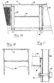
- the frame member 19 and the mounting member 20 are now to be described more closely with reference to Figs 5 to 7.
- the frame member 19 comprises four side pieces 21 connected to each other. Each side piece has a flange 22 directed inwardly towards the centre of the frame member 19.
- Each side piece 21 together with its associated flange 22 may be manufactured in one piece, preferably extruded aluminium. These pieces may then be welded to each other in the four corners of the frame member 19.
- a number of step plates 23, for example four may be inserted in such a manner that they rest against the flange 22.
- the step plates 23 may be manufactured in extruded aluminium, but also other materials are possible, for example steel plate or wood duckboards which may be inserted in the frame member 19.
- the mounting member 20 comprises a bottom plate 24 and two support plates 25 between which one of the side pieces of the frame member 19 is inserted. By means of one screw 26 provided in the outer support plate 25, the side piece 21 may be pressed against the other support plate 25 and be fixed to the mounting member 20.
- the bottom plate 24 has an elongated hole 27 for a screw 27a by means of which the mounting member 20 is fastened in the beam leg 10a. Because of the elongate shape of the hole 27, the mounting member 20 may be displaced laterally, in such a manner that the frame member 19 always may be inserted between the support plates 25, although a joint between two frame members would be located at the mounting member 20.
- the staircase 2 together with the extension piece 3 disclosed in Fig 1 is now to be explained more closely with reference to Figs 8 to 14.
- the staircase 2 is disclosed in Fig 8. It comprises a number of stairs 28, see Fig 11, and two side pieces 29, see Fig 12.
- the stairs 28 as well as the side pieces 29 may advantageously be manufactured in extruded aluminium, steel plate or any other high-strength material.
- the stairs 28 have a rough surface 30 provided on the upper side, which act as slip protection.
- the stairs 28 On the under side the stairs 28 have for instance three downwardly directed flanges 31 each of which has a downwardly open cavity 32 extending along the length of the stair and which may be provided with threads.
- the previously mentioned step plates 23 may have a profile similar to the one of the stairs 28.
- the step plates may be fixed in their position in the frame member 19 by means of screws or some kind of snap elements, for instance, (not disclosed), which engage the cavities 32.
- the side pieces 29 ought to have a high strength. They may therefore have a cross-section profile being stiff with respect to twisting, for example an L-shape, a Z-shape, a U-shape etc.
- the side pieces 29 have a U-shaped cross-section with a bottom and two legs being relatively short in relation to the bottom.
- the side piece 29 has rows of three holes 33 which are provided at the same mutual distance as the cavities 32.
- the stairs 28 are fixed to the two side pieces 29 by means of screws extending through the holes and threaded into the cavities 32.
- a connecting part 34 is provided at the upper end of the staircase 2. This is fastened by screws in the two side pieces 29.
- the connecting part 34 has a first portion 35 arranged to extend along the outer side of a side piece 21 of the frame member 19. This upper portion 35 is bent 180° and thus forms a second portion 36 arranged to extend along the inner side of the side piece 21.
- the staircase 2 may in a secure manner be hooked onto the frame member 19.
- the staircase 2 is extendible by the extension piece 3 disclosed in Figs 1 and 13. This piece comprises two extension side pieces 37, which have the same cross-section profile as the side pieces 29, and a stair 28 provided therebetween.
- the extension piece 3 comprises two connecting pieces 38, see Figs 13 and 14.
- the connecting pieces 38 are provided with a number of through-going holes, at least one of which is provided in the centre in such a manner that a screw 39 may extend through the extension side piece 37, the connecting piece 38 and into a cavity 32 of the stair 28 of the extension piece 3.
- the two upwardly projecting connecting pieces 38 are simply inserted into the two U-shaped opposite side pieces 29 of the staircase 2.
- the side piece 29 of the staircase 2 is screwed together with the connecting piece by means of screws (not disclosed).
- several extension pieces 3 may be provided one after the other and in such a manner that the total length of the staircase 2, 3 may be adapted to all practically existing heights.
- the railing 6 disclosed in Fig 1 is now to be explained more closely with reference to Figs 15 to 17.
- the railing 6 comprises pieces having a length corresponding to the length of the frame member 19.
- Each such railing piece comprises two upwardly projecting support members 40 and a transverse handrail 41.
- a further transverse support member 42 may be provided between the two support members 40.
- the two support members 40 have at their ends a through-going hole through which a screw 43 extends, which also extends through a hole in the side piece 21 of the frame member 19 and is fixedly tightened by means of a nut 44.
- the railing may be provided with a cover plate 45 provided between the support members 40.
Landscapes
- Engineering & Computer Science (AREA)
- Architecture (AREA)
- Civil Engineering (AREA)
- Structural Engineering (AREA)
- Mechanical Engineering (AREA)
- Physics & Mathematics (AREA)
- Electromagnetism (AREA)
- Steps, Ramps, And Handrails (AREA)
- Vehicle Body Suspensions (AREA)
- Eye Examination Apparatus (AREA)
- Push-Button Switches (AREA)
- Bay Windows, Entrances, And Structural Adjustments Related Thereto (AREA)
- Credit Cards Or The Like (AREA)
- Tents Or Canopies (AREA)
- Electrical Discharge Machining, Electrochemical Machining, And Combined Machining (AREA)
- Control And Other Processes For Unpacking Of Materials (AREA)
- Document Processing Apparatus (AREA)
- Replacing, Conveying, And Pick-Finding For Filamentary Materials (AREA)
- Memory System Of A Hierarchy Structure (AREA)
- Elevator Door Apparatuses (AREA)
- Ladders (AREA)
Applications Claiming Priority (3)
| Application Number | Priority Date | Filing Date | Title |
|---|---|---|---|
| SE9600486 | 1996-02-09 | ||
| SE9600486A SE504589C2 (sv) | 1996-02-09 | 1996-02-09 | Entréanordning för provisoriska byggnader |
| PCT/SE1997/000177 WO1997029259A1 (en) | 1996-02-09 | 1997-02-05 | An entrance device |
Publications (2)
| Publication Number | Publication Date |
|---|---|
| EP0879332A1 EP0879332A1 (en) | 1998-11-25 |
| EP0879332B1 true EP0879332B1 (en) | 2003-04-09 |
Family
ID=20401338
Family Applications (1)
| Application Number | Title | Priority Date | Filing Date |
|---|---|---|---|
| EP97904696A Expired - Lifetime EP0879332B1 (en) | 1996-02-09 | 1997-02-05 | An entrance device |
Country Status (7)
| Country | Link |
|---|---|
| EP (1) | EP0879332B1 (sv) |
| AT (1) | ATE237055T1 (sv) |
| DE (1) | DE69720692T2 (sv) |
| DK (1) | DK0879332T3 (sv) |
| NO (1) | NO310246B1 (sv) |
| SE (1) | SE504589C2 (sv) |
| WO (1) | WO1997029259A1 (sv) |
Families Citing this family (4)
| Publication number | Priority date | Publication date | Assignee | Title |
|---|---|---|---|---|
| FR2832744B1 (fr) * | 2001-11-23 | 2005-01-14 | Loxam Module | Unite de construction modulaire deplacable |
| WO2003074819A1 (en) * | 2002-03-07 | 2003-09-12 | Nimas Holding Aps | A staircase for a crew's container |
| CN108571126A (zh) * | 2018-05-09 | 2018-09-25 | 安徽富煌钢构股份有限公司 | 一种装配式楼梯 |
| SE544467C2 (en) * | 2018-12-11 | 2022-06-07 | Prefab Design System Stockholm Ab | Constructional system for providing structural arrangements to buildings |
Family Cites Families (2)
| Publication number | Priority date | Publication date | Assignee | Title |
|---|---|---|---|---|
| US4355700A (en) * | 1981-02-17 | 1982-10-26 | Matthews Wesley D | Modular stairway system for installation on structures having non-linear walls |
| DE9301494U1 (sv) * | 1993-02-04 | 1993-04-15 | Maegert Bautechnik Ag, Frutigen, Ch |
-
1996
- 1996-02-09 SE SE9600486A patent/SE504589C2/sv not_active IP Right Cessation
-
1997
- 1997-02-05 DK DK97904696T patent/DK0879332T3/da active
- 1997-02-05 WO PCT/SE1997/000177 patent/WO1997029259A1/en active IP Right Grant
- 1997-02-05 EP EP97904696A patent/EP0879332B1/en not_active Expired - Lifetime
- 1997-02-05 DE DE69720692T patent/DE69720692T2/de not_active Expired - Fee Related
- 1997-02-05 AT AT97904696T patent/ATE237055T1/de not_active IP Right Cessation
-
1998
- 1998-08-07 NO NO19983646A patent/NO310246B1/no unknown
Also Published As
| Publication number | Publication date |
|---|---|
| EP0879332A1 (en) | 1998-11-25 |
| DK0879332T3 (da) | 2003-06-02 |
| SE9600486D0 (sv) | 1996-02-09 |
| DE69720692T2 (de) | 2004-03-11 |
| ATE237055T1 (de) | 2003-04-15 |
| NO983646D0 (no) | 1998-08-07 |
| SE9600486L (sv) | 1997-03-10 |
| NO310246B1 (no) | 2001-06-11 |
| DE69720692D1 (de) | 2003-05-15 |
| SE504589C2 (sv) | 1997-03-10 |
| NO983646L (no) | 1998-10-08 |
| WO1997029259A1 (en) | 1997-08-14 |
Similar Documents
| Publication | Publication Date | Title |
|---|---|---|
| US5522186A (en) | Tree supported structure | |
| US7377491B2 (en) | Temporary structure bracket | |
| US5314167A (en) | Temporary rail structure for a floor | |
| US5560588A (en) | Support for temporary guard railing | |
| US20030208971A1 (en) | Modular stairway system, method for erecting stairway and kit therefor | |
| EP0879332B1 (en) | An entrance device | |
| US5214817A (en) | Modular ramp and landing walkway assembly | |
| US20030015696A1 (en) | Support for safety barrier | |
| GB1575091A (en) | Steep wooden staircase | |
| JPH05506486A (ja) | 改良された手摺のアンカ組立体 | |
| US7127868B2 (en) | Guardrail system for a roof of a building and associated methods | |
| KR200232471Y1 (ko) | 벽체 부착용 안전난간 클램프 | |
| JP3460013B2 (ja) | 階 段 | |
| EP1365087B1 (en) | Safety barrier apparatus | |
| JP2931561B2 (ja) | 手摺り構造物 | |
| JPS6237893Y2 (sv) | ||
| JP2600420Y2 (ja) | 手摺りユニット | |
| JP3078046B2 (ja) | 屋根足場 | |
| AU2008207557A1 (en) | Temporary Protective Structure | |
| AU5353699A (en) | Scaffolding assembly | |
| JPS6318652Y2 (sv) | ||
| JP2931560B2 (ja) | 手摺り構造物の化粧カバー取付構造 | |
| JP3054605B2 (ja) | 建物付設物の化粧カバー取付具 | |
| AU751694B2 (en) | Safety rail | |
| AU756703B2 (en) | Hanging scaffold assembly |
Legal Events
| Date | Code | Title | Description |
|---|---|---|---|
| PUAI | Public reference made under article 153(3) epc to a published international application that has entered the european phase |
Free format text: ORIGINAL CODE: 0009012 |
|
| 17P | Request for examination filed |
Effective date: 19980727 |
|
| AK | Designated contracting states |
Kind code of ref document: A1 Designated state(s): AT BE CH DE DK FI FR GB IE IT LI LU NL |
|
| GRAH | Despatch of communication of intention to grant a patent |
Free format text: ORIGINAL CODE: EPIDOS IGRA |
|
| GRAH | Despatch of communication of intention to grant a patent |
Free format text: ORIGINAL CODE: EPIDOS IGRA |
|
| GRAA | (expected) grant |
Free format text: ORIGINAL CODE: 0009210 |
|
| AK | Designated contracting states |
Designated state(s): AT BE CH DE DK FI FR GB IE IT LI LU NL |
|
| PG25 | Lapsed in a contracting state [announced via postgrant information from national office to epo] |
Ref country code: NL Free format text: LAPSE BECAUSE OF FAILURE TO SUBMIT A TRANSLATION OF THE DESCRIPTION OR TO PAY THE FEE WITHIN THE PRESCRIBED TIME-LIMIT Effective date: 20030409 Ref country code: IT Free format text: LAPSE BECAUSE OF FAILURE TO SUBMIT A TRANSLATION OF THE DESCRIPTION OR TO PAY THE FEE WITHIN THE PRE;WARNING: LAPSES OF ITALIAN PATENTS WITH EFFECTIVE DATE BEFORE 2007 MAY HAVE OCCURRED AT ANY TIME BEFORE 2007. THE CORRECT EFFECTIVE DATE MAY BE DIFFERENT FROM THE ONE RECORDED.SCRIBED TIME-LIMIT Effective date: 20030409 Ref country code: FI Free format text: LAPSE BECAUSE OF FAILURE TO SUBMIT A TRANSLATION OF THE DESCRIPTION OR TO PAY THE FEE WITHIN THE PRESCRIBED TIME-LIMIT Effective date: 20030409 Ref country code: BE Free format text: LAPSE BECAUSE OF FAILURE TO SUBMIT A TRANSLATION OF THE DESCRIPTION OR TO PAY THE FEE WITHIN THE PRESCRIBED TIME-LIMIT Effective date: 20030409 Ref country code: AT Free format text: LAPSE BECAUSE OF FAILURE TO SUBMIT A TRANSLATION OF THE DESCRIPTION OR TO PAY THE FEE WITHIN THE PRESCRIBED TIME-LIMIT Effective date: 20030409 |
|
| REG | Reference to a national code |
Ref country code: GB Ref legal event code: FG4D |
|
| REG | Reference to a national code |
Ref country code: CH Ref legal event code: EP |
|
| REG | Reference to a national code |
Ref country code: IE Ref legal event code: FG4D |
|
| REG | Reference to a national code |
Ref country code: DK Ref legal event code: T3 |
|
| REG | Reference to a national code |
Ref country code: CH Ref legal event code: NV Representative=s name: HANS RUDOLF GACHNANG PATENTANWALT |
|
| NLV1 | Nl: lapsed or annulled due to failure to fulfill the requirements of art. 29p and 29m of the patents act | ||
| ET | Fr: translation filed | ||
| PG25 | Lapsed in a contracting state [announced via postgrant information from national office to epo] |
Ref country code: LU Free format text: LAPSE BECAUSE OF NON-PAYMENT OF DUE FEES Effective date: 20040205 |
|
| PLBE | No opposition filed within time limit |
Free format text: ORIGINAL CODE: 0009261 |
|
| STAA | Information on the status of an ep patent application or granted ep patent |
Free format text: STATUS: NO OPPOSITION FILED WITHIN TIME LIMIT |
|
| 26N | No opposition filed |
Effective date: 20040112 |
|
| PGFP | Annual fee paid to national office [announced via postgrant information from national office to epo] |
Ref country code: IE Payment date: 20060111 Year of fee payment: 10 |
|
| PGFP | Annual fee paid to national office [announced via postgrant information from national office to epo] |
Ref country code: GB Payment date: 20070103 Year of fee payment: 11 |
|
| PGFP | Annual fee paid to national office [announced via postgrant information from national office to epo] |
Ref country code: CH Payment date: 20070223 Year of fee payment: 11 |
|
| REG | Reference to a national code |
Ref country code: CH Ref legal event code: NV Representative=s name: HANS ULRICH SEIFERT SEIFERT & PARTNER |
|
| REG | Reference to a national code |
Ref country code: IE Ref legal event code: MM4A |
|
| PG25 | Lapsed in a contracting state [announced via postgrant information from national office to epo] |
Ref country code: IE Free format text: LAPSE BECAUSE OF NON-PAYMENT OF DUE FEES Effective date: 20070205 |
|
| PGFP | Annual fee paid to national office [announced via postgrant information from national office to epo] |
Ref country code: FR Payment date: 20070126 Year of fee payment: 11 Ref country code: DK Payment date: 20080226 Year of fee payment: 12 |
|
| PGFP | Annual fee paid to national office [announced via postgrant information from national office to epo] |
Ref country code: DE Payment date: 20080423 Year of fee payment: 12 |
|
| REG | Reference to a national code |
Ref country code: CH Ref legal event code: PL |
|
| GBPC | Gb: european patent ceased through non-payment of renewal fee |
Effective date: 20080205 |
|
| PG25 | Lapsed in a contracting state [announced via postgrant information from national office to epo] |
Ref country code: LI Free format text: LAPSE BECAUSE OF NON-PAYMENT OF DUE FEES Effective date: 20080229 Ref country code: CH Free format text: LAPSE BECAUSE OF NON-PAYMENT OF DUE FEES Effective date: 20080229 |
|
| REG | Reference to a national code |
Ref country code: FR Ref legal event code: ST Effective date: 20081031 |
|
| PG25 | Lapsed in a contracting state [announced via postgrant information from national office to epo] |
Ref country code: FR Free format text: LAPSE BECAUSE OF NON-PAYMENT OF DUE FEES Effective date: 20080229 |
|
| PG25 | Lapsed in a contracting state [announced via postgrant information from national office to epo] |
Ref country code: GB Free format text: LAPSE BECAUSE OF NON-PAYMENT OF DUE FEES Effective date: 20080205 |
|
| REG | Reference to a national code |
Ref country code: DK Ref legal event code: EBP |
|
| PG25 | Lapsed in a contracting state [announced via postgrant information from national office to epo] |
Ref country code: DE Free format text: LAPSE BECAUSE OF NON-PAYMENT OF DUE FEES Effective date: 20090901 |
|
| PG25 | Lapsed in a contracting state [announced via postgrant information from national office to epo] |
Ref country code: DK Free format text: LAPSE BECAUSE OF NON-PAYMENT OF DUE FEES Effective date: 20090831 |