EP0879107B1 - Metal cutting tool and replaceable shim therefor - Google Patents
Metal cutting tool and replaceable shim therefor Download PDFInfo
- Publication number
- EP0879107B1 EP0879107B1 EP97900730A EP97900730A EP0879107B1 EP 0879107 B1 EP0879107 B1 EP 0879107B1 EP 97900730 A EP97900730 A EP 97900730A EP 97900730 A EP97900730 A EP 97900730A EP 0879107 B1 EP0879107 B1 EP 0879107B1
- Authority
- EP
- European Patent Office
- Prior art keywords
- rib
- shim
- portions
- recess
- Prior art date
- Legal status (The legal status is an assumption and is not a legal conclusion. Google has not performed a legal analysis and makes no representation as to the accuracy of the status listed.)
- Expired - Lifetime
Links
Images


Classifications
-
- B—PERFORMING OPERATIONS; TRANSPORTING
- B23—MACHINE TOOLS; METAL-WORKING NOT OTHERWISE PROVIDED FOR
- B23B—TURNING; BORING
- B23B27/00—Tools for turning or boring machines; Tools of a similar kind in general; Accessories therefor
- B23B27/14—Cutting tools of which the bits or tips or cutting inserts are of special material
- B23B27/16—Cutting tools of which the bits or tips or cutting inserts are of special material with exchangeable cutting bits or cutting inserts, e.g. able to be clamped
- B23B27/1662—Cutting tools of which the bits or tips or cutting inserts are of special material with exchangeable cutting bits or cutting inserts, e.g. able to be clamped with plate-like cutting inserts clamped against the walls of the recess in the shank by a clamping member acting upon the wall of a hole in the cutting insert
-
- B—PERFORMING OPERATIONS; TRANSPORTING
- B23—MACHINE TOOLS; METAL-WORKING NOT OTHERWISE PROVIDED FOR
- B23B—TURNING; BORING
- B23B2205/00—Fixation of cutting inserts in holders
- B23B2205/16—Shims
-
- Y—GENERAL TAGGING OF NEW TECHNOLOGICAL DEVELOPMENTS; GENERAL TAGGING OF CROSS-SECTIONAL TECHNOLOGIES SPANNING OVER SEVERAL SECTIONS OF THE IPC; TECHNICAL SUBJECTS COVERED BY FORMER USPC CROSS-REFERENCE ART COLLECTIONS [XRACs] AND DIGESTS
- Y10—TECHNICAL SUBJECTS COVERED BY FORMER USPC
- Y10T—TECHNICAL SUBJECTS COVERED BY FORMER US CLASSIFICATION
- Y10T407/00—Cutters, for shaping
- Y10T407/19—Rotary cutting tool
- Y10T407/1906—Rotary cutting tool including holder [i.e., head] having seat for inserted tool
- Y10T407/1908—Face or end mill
- Y10T407/192—Face or end mill with separate means to fasten tool to holder
-
- Y—GENERAL TAGGING OF NEW TECHNOLOGICAL DEVELOPMENTS; GENERAL TAGGING OF CROSS-SECTIONAL TECHNOLOGIES SPANNING OVER SEVERAL SECTIONS OF THE IPC; TECHNICAL SUBJECTS COVERED BY FORMER USPC CROSS-REFERENCE ART COLLECTIONS [XRACs] AND DIGESTS
- Y10—TECHNICAL SUBJECTS COVERED BY FORMER USPC
- Y10T—TECHNICAL SUBJECTS COVERED BY FORMER US CLASSIFICATION
- Y10T407/00—Cutters, for shaping
- Y10T407/22—Cutters, for shaping including holder having seat for inserted tool
- Y10T407/2272—Cutters, for shaping including holder having seat for inserted tool with separate means to fasten tool to holder
- Y10T407/2274—Apertured tool
- Y10T407/2276—Apertured tool with means projecting through aperture to force tool laterally against reaction surface
Definitions
- This invention relates to a metal cutting tool comprising a tool holder formed with one or more insert receiving pockets, each pocket being provided with a replaceable shim.
- the or each cutting insert is releasably retained in a respective pocket formed in a tool holder by, for example, a clamping screw which extends through a central hole formed in the insert into an appropriate tapped bore formed in the tool holder or, alternatively, by some other suitable clamping system.
- a clamping screw which extends through a central hole formed in the insert into an appropriate tapped bore formed in the tool holder or, alternatively, by some other suitable clamping system.
- the interposition of a shim between the insert and the base surface of the tool holder pocket serves to protect the relatively costly tool holder body from deformation or damage through use. Shims of differing heights can be employed so as to vary, as required, the specific location of the cutting insert and in particular that of the cutting edge with respect to the tool holder.
- the seating shim proposed in our prior U.S. patent in common with most, if not all, prior art seating shims, are made from cast steel and therefore have to undergo significant metal cutting operations such as drilling and grinding after heat treatment, so as to render them suitable for use. In consequence, the shim cannot readily be mass produced.
- a cutting tool comprising a tool holder; a receiving and retaining pocket formed in said tool holder; base and side walls of said pocket; a cylindrical recess formed in a region of a junction of the base and a side wall of said pocket coextensive with and opening out into said pocket via a slot having a transverse dimension D 1 and being of substantially circular arc-like cross-sectional shape having a diameter d 1 where d 1 >D 1 and subtending an angle greater than 180°; and a replaceable shim formed by pressing and sintering a metal powder and comprising a plate-like body portion having upper, base and side walls; a rib member formed integrally with one of said side walls and projecting beyond said base wall of said body portion, an outer surface of said rib member, transversely opposing portions of said outer surface substantially symmetrically disposed along the length of said rib being located on a right circular cylindrical envelope of diameter d 2 which subtends an angle of at least 180°,
- said opposing portions are constituted by axially directed, cylindrical strips which can either extend along the entire length of the rib or along central or terminal extents thereof.
- the or each peripheral portion can be formed between axially extending substantially planar surfaces of the rib, of which a pair can be mutually perpendicular. These planar surfaces can be substantially parallel with one of them being substantially flush with an upper wall of the body portion.
- the shim in accordance with the invention, it can be formed by the powder metallurgy technology of compacting and sintering, the resulting product being very much harder than the previously produced cast steel shims. Furthermore, the product can be mass produced at relatively low cost, requiring only the grinding of the upper surface and honing around. Furthermore, the integrally formed positioning and retaining rib is readily and freely insertable into a correspondingly formed cylindrical recess in the insert retaining pocket. A simple pivotal movement of the rib with respect to the recess results in the frictional gripping of the rib within the recess and the effective retention of the shim in the receiving pocket with the shim in close abutment with the base wall of the pocket.
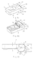
- FIG. 1 and 2 of the drawings illustrate the application of the invention to a cutting tool in the form of a substantially standard milling cutter 1 which is formed with a plurality of peripherally distributed recesses 2, each recess having formed therein an insert retaining pocket 3 shown clearly in Fig. 3 of the drawings.
- Each pocket 3 is defined by a pair of side walls 4 and 5 and a base wall 6.
- An elongated cylindrical recess 7 is formed at the junction of the side wall 5 and the base wall 6 and opens into the pocket 3 via an elongated slot 8 which is co-directional with what would otherwise have been the linear junction of the side wall 5 and the base wall 6.
- Extending centrally into the base wall 6 is a tapped aperture 9.
- An insert seating shim 11 formed by pressing and sintering a metal powder is constituted by a substantially rectangular plate-like body portion 12 having an upper planar surface 13, a lower base surface 14 and a surrounding side surface 15.
- the base surface 14 substantially corresponds in dimensions with those of the base wall 6 of the pocket 3.
- Formed in the body portion 12 is a throughgoing aperture 12a.
- Formed integrally with a side surface 15 of the body portion 12 is a rib retaining member 16 which is coextensive with the side surface with which it is integral.
- the rib member 16 has an outer surface which is of substantially circular arcuate cross-sectional shape having, as seen in Figs. 3c and 7 of the drawings, a diameter d 2 and subtending an angle greater than 180°.
- the rib member 16 has an upper, planar surface 17 which, as shown, is preferably flush with the upper, planar surface 13 of the body portion 12 of the seating shim 11.
- the rib member 16 projects beyond the base surface 14 of the body portion 12, having a lowermost, substantially flat, axially directed surface 18 substantially parallel with the upper surface 17 and the upper and base surfaces 13 and 14 of the body portion 12.
- the flattened surfaces 17 and 18 are spaced apart by a distance D 2 .
- cylindrical peripheral portions or strip portions 19 and 20 on either side of the flattened surface 18 are cylindrical peripheral portions or strip portions 19 and 20, whilst the upper surface 17 merges with a cylindrical strip portion 21.
- the peripheral portions 19, 20 and 21 lie on a right circular cylindrical envelope of diameter d 2 having an axis 23.
- the cylindrical peripheral portions 21 and 20 are separated by a flattened portion 22.
- the flattened portion 22 is inset with respect to the cylindrical envelope and is substantially normal to the surfaces 17 and 18 and is located symmetrically with respect to an axis 23.
- the base wall 14 of the shim body portion 12 is formed at its outermost comers with a pair of abutment surfaces 25.
- the cylindrical recess is of substantially circular, arc-like, cross-sectional shape subtending an angle greater than 180° and having a diameter d 1 .
- the cylindrical recess 7 formed in the tool holder opens out into the pocket via the elongated slot 8 with which it is coextensive.
- the slot 8 has a transverse dimension D 1 where d 1 ⁇ D 1 .
- the spacing D 2 between the flat surface portions 17 and 18 of the rib 16 must not be greater than the transverse dimension D 1 of the slot 8.
- the diameter d 2 of the right circular cylindrical envelope on which the cylindrically peripheral portions 19, 20 and 21 lie is very slightly greater than the diameter d 1 of the recess.
- the shim 11 is orientated with respect to the base wall 6 of the pocket 3 by an acute angle ⁇ , the rib member 16 can be readily inserted into the recess 7 seeing that its minimum lateral spacing D 2 is not greater than the lateral dimension D 1 of the slot.
- the shim 11 is pivotally displaced with respect to the recess 7 in an anti-clockwise direction towards the base wall 6 of the pocket 3, the peripheral portions 19, 20 and 21 slide in tight, frictional contact with the inner surface of the cylindrical recess 7 so that, when the base surface 14 of the body portion 12 of the shim 11 has reached its final position with the abutment surfaces 25 in close abutment with the base wall 6 of the pocket 3, the rib member 16 is tightly retained within the recess 7 and, in consequence, the shim 11 as a whole is retained in position in pocket 3, as seen in Fig. 8.
- a cutting insert 26 When in this position, a cutting insert 26 can be placed on the shim 11 and can be firmly secured to the tool holder by means of a locking screw 27 passing through the insert and the shim for screw tightening within the pocket.
- the area of abutment of the rib within the recess is directed to the region where the main cutting forces act and, at the same time, firm seating of the shim in the pocket is ensured within reasonable tolerance levels.
- Removal of the insert 26 has no effect on the retention of the shim 11 in the. pocket 3 and when it is desired to remove the shim 11 from the pocket 3, the shim 11 is rotated in a clockwise direction away from the base 6 of the pocket 3 until the flat surface portions 17 and 18 of the rib 16 are aligned with the edges of the slot 8, allowing for the rib member 16 to be extracted from the recess 7.
- a rib member 30 is formed with cylindrically peripheral strip portions 32, 33 and 34 which are separated from each other by substantially flat portions 35 and 36.
- Each of the peripheral portions 32, 32 and 34 is located on a central section 37 which lies on a cylindrical envelope of diameter d 2 , whilst the terminal sections 38 of each such peripheral portions 32, 33 and 34 lie on a cylindrical envelope having a lesser diameter.
- the rib member may be provided at its terminal portions with cylindrically curved strip portions of a diameter so as to slide frictionally within the cylindrical recess, these terminal portions being separated by central portions of reduced diameter.
- the limitation of the lengths of the strip portions which fit frictionally within the cylindrical recess ensures that the reduction in contact area with the surface of the cylindrical recess reduces the frictional resistance to insertion and pivotal displacement of the rib member into the cylindrical recess.
- the cylindrically curved strip portion 20 shown in Figs. 3a, 3b and 3c has been replaced by a chamfered portion 39 no longer in contact with the adjacent surface of the cylindrical recess.
- the tolerance requirements for the rib member are reduced, leading to a simplification in manufacture.
- the contact of one of the cylindrically curved strip portions with the recess surface can be replaced by an effective line contact located on the same cylindrical envelope as an oppositely disposed curved peripheral portion.
- the rib members 16, 31 are formed integrally with a side surface of the shim member which, in the tool, is directed radially with respect to the tool, it will be appreciated that retention of the shim member in the tool holder can be equally well effected if the rib member is associated with an axially directed side surface and the recess formed in the pocket of the tool holder is also directed axially.
- the tool was designed to have the following dimensions:
- the lengths of the central strip portions 32, 33 and 34 which are in contact with the adjacent surface of the recess should not be less than 0.25 the overall length of the strip.
Landscapes
- Engineering & Computer Science (AREA)
- Mechanical Engineering (AREA)
- Cutting Tools, Boring Holders, And Turrets (AREA)
- Milling Processes (AREA)
- Turning (AREA)
- Drilling Tools (AREA)
- Knives (AREA)
- Powder Metallurgy (AREA)
- Milling, Broaching, Filing, Reaming, And Others (AREA)
Applications Claiming Priority (3)
| Application Number | Priority Date | Filing Date | Title |
|---|---|---|---|
| IL11701596 | 1996-02-02 | ||
| IL11701596A IL117015A (en) | 1996-02-02 | 1996-02-02 | Cutting Tools |
| PCT/IL1997/000040 WO1997027966A1 (en) | 1996-02-02 | 1997-01-30 | Metal cutting tool and replaceable shim therefor |
Publications (2)
| Publication Number | Publication Date |
|---|---|
| EP0879107A1 EP0879107A1 (en) | 1998-11-25 |
| EP0879107B1 true EP0879107B1 (en) | 2001-10-17 |
Family
ID=11068512
Family Applications (1)
| Application Number | Title | Priority Date | Filing Date |
|---|---|---|---|
| EP97900730A Expired - Lifetime EP0879107B1 (en) | 1996-02-02 | 1997-01-30 | Metal cutting tool and replaceable shim therefor |
Country Status (20)
| Country | Link |
|---|---|
| US (1) | US5836724A (https=) |
| EP (1) | EP0879107B1 (https=) |
| JP (2) | JP3895777B2 (https=) |
| KR (1) | KR100447373B1 (https=) |
| AR (1) | AR005682A1 (https=) |
| AT (1) | ATE206977T1 (https=) |
| AU (2) | AU1318397A (https=) |
| BR (1) | BR9706862A (https=) |
| CA (1) | CA2237567C (https=) |
| CZ (1) | CZ288969B6 (https=) |
| DE (3) | DE879107T1 (https=) |
| ES (1) | ES2127168T1 (https=) |
| HU (1) | HUP9902279A3 (https=) |
| IL (1) | IL117015A (https=) |
| MX (1) | MX9805344A (https=) |
| PL (1) | PL327326A1 (https=) |
| SK (1) | SK76198A3 (https=) |
| TR (1) | TR199800593T2 (https=) |
| WO (1) | WO1997027966A1 (https=) |
| ZA (1) | ZA97778B (https=) |
Families Citing this family (20)
| Publication number | Priority date | Publication date | Assignee | Title |
|---|---|---|---|---|
| IL131260A (en) * | 1999-08-05 | 2003-07-31 | Iscar Ltd | Cutting tool assembly and cutting insert |
| DE10228503A1 (de) * | 2002-06-21 | 2004-01-15 | MAPAL Fabrik für Präzisionswerkzeuge Dr. Kress KG | Werkzeug zur spanenden Bearbeitung von Ventilsitzen |
| US7004689B2 (en) * | 2004-01-09 | 2006-02-28 | Kennametal Inc. | High-speed milling cutter and insert |
| US7070363B2 (en) | 2004-07-15 | 2006-07-04 | Kennametal Inc. | Cutting insert for high-speed milling cutter |
| SE530374C2 (sv) * | 2006-05-23 | 2008-05-20 | Pramet Tools Sro | Skärinsats samt skärverktyg där fastspänningshålets fastspänningsyta har formen av en elliptisk kon |
| DE102008001857A1 (de) * | 2007-05-22 | 2008-11-27 | Ceramtec Ag | Plattensitz mit Einlegestücken |
| DE112008002324B4 (de) * | 2007-08-30 | 2017-11-02 | Kyocera Corporation | Schneidwerkzeug und Schneidverfahren |
| WO2010097797A1 (en) | 2009-02-27 | 2010-09-02 | No Screw Ltd. | Cutting tool, cutting tool holder and cutting insert therefor |
| EP2459961A4 (en) * | 2009-07-31 | 2012-12-26 | Hewlett Packard Development Co | BEAM DIRECTION SENSOR |
| US8974154B2 (en) * | 2011-03-11 | 2015-03-10 | Sandvik Intellectual Property Ab | Cutting insert and shim for milling cutters |
| US9145741B2 (en) | 2011-06-13 | 2015-09-29 | Baker Hughes Incorporated | Cutting elements comprising sensors, earth-boring tools having such sensors, and associated methods |
| EP2596887B1 (en) | 2011-11-23 | 2019-01-23 | Sandvik Intellectual Property AB | Cutting tool comprising an exchangeable insert seat member |
| WO2015033338A2 (en) | 2013-09-03 | 2015-03-12 | No Screw Ltd. | Mounting mechanism for a cutting insert, a cutting insert therefor and a cutting tool using said insert |
| EP3162481B1 (en) * | 2014-06-24 | 2022-12-21 | Sumitomo Electric Hardmetal Corp. | Cutting tool and tool body |
| US10307833B2 (en) | 2015-02-04 | 2019-06-04 | No Screw Ltd. | Cutting tool comprising a cutting tool holder and a cutting insert therefor |
| ES2703547T3 (es) * | 2015-04-01 | 2019-03-11 | Ledermann Gmbh & Co Kg | Herramienta fresadora y elemento de corte para su uso en una herramienta fresadora |
| EP3288701A1 (en) | 2015-04-30 | 2018-03-07 | No Screw Ltd. | Dynamic clamping mechanism |
| EP3246117A1 (en) * | 2016-05-20 | 2017-11-22 | Seco Tools Ab | Cutting tool and shim |
| JP7045460B2 (ja) * | 2018-08-01 | 2022-03-31 | 京セラ株式会社 | 切削工具及び切削加工物の製造方法 |
| US11453065B2 (en) * | 2019-05-24 | 2022-09-27 | Iscar, Ltd. | Cutting insert having lower anti-slip recess, insert holder and cutting tool |
Family Cites Families (7)
| Publication number | Priority date | Publication date | Assignee | Title |
|---|---|---|---|---|
| US3829943A (en) * | 1971-02-19 | 1974-08-20 | Fansteel Inc | Threading tool |
| US4470732A (en) * | 1980-12-22 | 1984-09-11 | Lindsay Harold W | Tool holder with retaining lip |
| DE3414435A1 (de) * | 1984-04-17 | 1985-10-17 | Feldmühle AG, 4000 Düsseldorf | Klemmstahlhalter mit eingesetzter schneidplatte |
| SE452274B (sv) * | 1986-05-21 | 1987-11-23 | Seco Tools Ab | Anordning for fastspenning av ett halforsett, positivt sker |
| US4826090A (en) * | 1987-11-09 | 1989-05-02 | Orphall Axel W | Hammer assembly for a rotary material crusher |
| GB9003697D0 (en) * | 1990-02-19 | 1990-04-18 | Iscar Hartmetall | A metal cutting tool |
| WO1995005913A1 (en) * | 1993-08-25 | 1995-03-02 | Kennametal Inc. | Milling cutter with insert adapter______________________________ |
-
1996
- 1996-02-02 IL IL11701596A patent/IL117015A/en not_active IP Right Cessation
-
1997
- 1997-01-30 ES ES97900730T patent/ES2127168T1/es active Pending
- 1997-01-30 WO PCT/IL1997/000040 patent/WO1997027966A1/en not_active Ceased
- 1997-01-30 CA CA002237567A patent/CA2237567C/en not_active Expired - Fee Related
- 1997-01-30 BR BR9706862-4A patent/BR9706862A/pt not_active Application Discontinuation
- 1997-01-30 KR KR10-1998-0704575A patent/KR100447373B1/ko not_active Expired - Lifetime
- 1997-01-30 HU HU9902279A patent/HUP9902279A3/hu unknown
- 1997-01-30 JP JP52746297A patent/JP3895777B2/ja not_active Expired - Lifetime
- 1997-01-30 AU AU13183/97A patent/AU1318397A/en not_active Abandoned
- 1997-01-30 ZA ZA97778A patent/ZA97778B/xx unknown
- 1997-01-30 DE DE0879107T patent/DE879107T1/de active Pending
- 1997-01-30 AT AT97900730T patent/ATE206977T1/de active
- 1997-01-30 TR TR1998/00593T patent/TR199800593T2/xx unknown
- 1997-01-30 SK SK761-98A patent/SK76198A3/sk unknown
- 1997-01-30 CZ CZ19981759A patent/CZ288969B6/cs not_active IP Right Cessation
- 1997-01-30 EP EP97900730A patent/EP0879107B1/en not_active Expired - Lifetime
- 1997-01-30 PL PL97327326A patent/PL327326A1/xx unknown
- 1997-01-30 AU AU12401/97A patent/AU676824B3/en not_active Ceased
- 1997-01-30 DE DE69707424T patent/DE69707424T2/de not_active Expired - Lifetime
- 1997-01-31 AR ARP970100414A patent/AR005682A1/es unknown
- 1997-01-31 US US08/792,306 patent/US5836724A/en not_active Expired - Lifetime
- 1997-01-31 DE DE29701693U patent/DE29701693U1/de not_active Expired - Lifetime
- 1997-02-03 JP JP1997000740U patent/JP3043599U/ja not_active Expired - Lifetime
-
1998
- 1998-06-30 MX MX9805344A patent/MX9805344A/es unknown
Also Published As
| Publication number | Publication date |
|---|---|
| HUP9902279A2 (hu) | 1999-11-29 |
| JP3895777B2 (ja) | 2007-03-22 |
| JP3043599U (ja) | 1997-11-28 |
| DE879107T1 (de) | 1999-06-02 |
| CZ288969B6 (cs) | 2001-10-17 |
| CZ175998A3 (cs) | 1998-12-16 |
| KR19990072202A (ko) | 1999-09-27 |
| SK76198A3 (en) | 1999-01-11 |
| ES2127168T1 (es) | 1999-04-16 |
| KR100447373B1 (ko) | 2004-10-15 |
| EP0879107A1 (en) | 1998-11-25 |
| ZA97778B (en) | 1998-07-30 |
| CA2237567A1 (en) | 1997-08-07 |
| TR199800593T2 (xx) | 1998-07-21 |
| AU1318397A (en) | 1997-08-22 |
| AU676824B3 (en) | 1997-03-20 |
| ATE206977T1 (de) | 2001-11-15 |
| DE29701693U1 (de) | 1997-03-20 |
| MX9805344A (es) | 1998-10-31 |
| US5836724A (en) | 1998-11-17 |
| IL117015A (en) | 1998-12-27 |
| IL117015A0 (en) | 1996-06-18 |
| HUP9902279A3 (en) | 2000-03-28 |
| DE69707424T2 (de) | 2002-06-20 |
| CA2237567C (en) | 2001-09-04 |
| AR005682A1 (es) | 1999-07-14 |
| BR9706862A (pt) | 2000-01-25 |
| DE69707424D1 (de) | 2001-11-22 |
| JP2000503913A (ja) | 2000-04-04 |
| WO1997027966A1 (en) | 1997-08-07 |
| PL327326A1 (en) | 1998-12-07 |
Similar Documents
| Publication | Publication Date | Title |
|---|---|---|
| EP0879107B1 (en) | Metal cutting tool and replaceable shim therefor | |
| EP0638384B1 (en) | A cutting insert | |
| EP1918052B1 (en) | Cutting insert as well as combination of a cutting insert and an insert holder | |
| EP0925137B1 (en) | Cutting insert | |
| EP1635977B1 (en) | A milling tool with co-operating projections and recessess between the cutting insert and the holder | |
| US7578640B2 (en) | Cutting tool having cutting insert secured by non-penetrating abutment of a threaded fastener | |
| EP2176021B1 (en) | Cutting tool and cutting insert therefor | |
| KR101289297B1 (ko) | 선삭 공구, 인덱서블 선삭 인서트 및 그러한 선삭 공구의부착물 | |
| EP0152729A2 (en) | Chip cutting tool | |
| EP3717162B1 (en) | Slitting cutter | |
| KR20050109572A (ko) | 상이한 반경을 지닌 코너부를 가지는 인덱서블 인서트 | |
| EP0443773B1 (en) | A metal cutting tool | |
| KR100599945B1 (ko) | 세라믹 절삭인서트 | |
| EP1200220B1 (en) | Cutting tool assembly | |
| EP0638385A1 (en) | Cutting tool | |
| CN1204975A (zh) | 金属切削工具及其可换垫片 | |
| EP0362505A1 (en) | Positive rake insert locating means |
Legal Events
| Date | Code | Title | Description |
|---|---|---|---|
| PUAI | Public reference made under article 153(3) epc to a published international application that has entered the european phase |
Free format text: ORIGINAL CODE: 0009012 |
|
| 17P | Request for examination filed |
Effective date: 19980317 |
|
| AK | Designated contracting states |
Kind code of ref document: A1 Designated state(s): AT BE CH DE DK ES FI FR GB IT LI NL PT SE |
|
| AX | Request for extension of the european patent |
Free format text: RO PAYMENT 980402;SI PAYMENT 980317 |
|
| TCAT | At: translation of patent claims filed | ||
| ITCL | It: translation for ep claims filed |
Representative=s name: STUDIO INGG. FISCHETTI & WEBER |
|
| TCNL | Nl: translation of patent claims filed | ||
| EL | Fr: translation of claims filed | ||
| 17Q | First examination report despatched |
Effective date: 19990226 |
|
| REG | Reference to a national code |
Ref country code: ES Ref legal event code: BA2A Ref document number: 2127168 Country of ref document: ES Kind code of ref document: T1 |
|
| DET | De: translation of patent claims | ||
| GRAG | Despatch of communication of intention to grant |
Free format text: ORIGINAL CODE: EPIDOS AGRA |
|
| GRAG | Despatch of communication of intention to grant |
Free format text: ORIGINAL CODE: EPIDOS AGRA |
|
| GRAG | Despatch of communication of intention to grant |
Free format text: ORIGINAL CODE: EPIDOS AGRA |
|
| GRAH | Despatch of communication of intention to grant a patent |
Free format text: ORIGINAL CODE: EPIDOS IGRA |
|
| GRAH | Despatch of communication of intention to grant a patent |
Free format text: ORIGINAL CODE: EPIDOS IGRA |
|
| ITF | It: translation for a ep patent filed | ||
| GRAA | (expected) grant |
Free format text: ORIGINAL CODE: 0009210 |
|
| AK | Designated contracting states |
Kind code of ref document: B1 Designated state(s): AT BE CH DE DK ES FI FR GB IT LI NL PT SE |
|
| AX | Request for extension of the european patent |
Free format text: RO PAYMENT 19980402;SI PAYMENT 19980317 |
|
| PG25 | Lapsed in a contracting state [announced via postgrant information from national office to epo] |
Ref country code: NL Free format text: LAPSE BECAUSE OF FAILURE TO SUBMIT A TRANSLATION OF THE DESCRIPTION OR TO PAY THE FEE WITHIN THE PRESCRIBED TIME-LIMIT Effective date: 20011017 Ref country code: LI Free format text: LAPSE BECAUSE OF FAILURE TO SUBMIT A TRANSLATION OF THE DESCRIPTION OR TO PAY THE FEE WITHIN THE PRESCRIBED TIME-LIMIT Effective date: 20011017 Ref country code: FI Free format text: LAPSE BECAUSE OF FAILURE TO SUBMIT A TRANSLATION OF THE DESCRIPTION OR TO PAY THE FEE WITHIN THE PRESCRIBED TIME-LIMIT Effective date: 20011017 Ref country code: CH Free format text: LAPSE BECAUSE OF FAILURE TO SUBMIT A TRANSLATION OF THE DESCRIPTION OR TO PAY THE FEE WITHIN THE PRESCRIBED TIME-LIMIT Effective date: 20011017 Ref country code: BE Free format text: LAPSE BECAUSE OF FAILURE TO SUBMIT A TRANSLATION OF THE DESCRIPTION OR TO PAY THE FEE WITHIN THE PRESCRIBED TIME-LIMIT Effective date: 20011017 Ref country code: AT Free format text: LAPSE BECAUSE OF FAILURE TO SUBMIT A TRANSLATION OF THE DESCRIPTION OR TO PAY THE FEE WITHIN THE PRESCRIBED TIME-LIMIT Effective date: 20011017 |
|
| REF | Corresponds to: |
Ref document number: 206977 Country of ref document: AT Date of ref document: 20011115 Kind code of ref document: T |
|
| REG | Reference to a national code |
Ref country code: CH Ref legal event code: EP |
|
| REF | Corresponds to: |
Ref document number: 69707424 Country of ref document: DE Date of ref document: 20011122 |
|
| REG | Reference to a national code |
Ref country code: GB Ref legal event code: IF02 |
|
| PG25 | Lapsed in a contracting state [announced via postgrant information from national office to epo] |
Ref country code: PT Free format text: LAPSE BECAUSE OF FAILURE TO SUBMIT A TRANSLATION OF THE DESCRIPTION OR TO PAY THE FEE WITHIN THE PRESCRIBED TIME-LIMIT Effective date: 20020117 Ref country code: DK Free format text: LAPSE BECAUSE OF FAILURE TO SUBMIT A TRANSLATION OF THE DESCRIPTION OR TO PAY THE FEE WITHIN THE PRESCRIBED TIME-LIMIT Effective date: 20020117 |
|
| ET | Fr: translation filed | ||
| NLV1 | Nl: lapsed or annulled due to failure to fulfill the requirements of art. 29p and 29m of the patents act | ||
| PG25 | Lapsed in a contracting state [announced via postgrant information from national office to epo] |
Ref country code: ES Free format text: LAPSE BECAUSE OF FAILURE TO SUBMIT A TRANSLATION OF THE DESCRIPTION OR TO PAY THE FEE WITHIN THE PRESCRIBED TIME-LIMIT Effective date: 20020430 |
|
| REG | Reference to a national code |
Ref country code: CH Ref legal event code: PL |
|
| PLBE | No opposition filed within time limit |
Free format text: ORIGINAL CODE: 0009261 |
|
| STAA | Information on the status of an ep patent application or granted ep patent |
Free format text: STATUS: NO OPPOSITION FILED WITHIN TIME LIMIT |
|
| 26N | No opposition filed | ||
| REG | Reference to a national code |
Ref country code: GB Ref legal event code: 732E |
|
| REG | Reference to a national code |
Ref country code: FR Ref legal event code: TP Ref country code: FR Ref legal event code: CD |
|
| PG25 | Lapsed in a contracting state [announced via postgrant information from national office to epo] |
Ref country code: IT Free format text: LAPSE BECAUSE OF NON-PAYMENT OF DUE FEES Effective date: 20090130 |
|
| PGRI | Patent reinstated in contracting state [announced from national office to epo] |
Ref country code: IT Effective date: 20110616 |
|
| REG | Reference to a national code |
Ref country code: FR Ref legal event code: PLFP Year of fee payment: 19 |
|
| PGFP | Annual fee paid to national office [announced via postgrant information from national office to epo] |
Ref country code: IT Payment date: 20150116 Year of fee payment: 19 Ref country code: DE Payment date: 20141230 Year of fee payment: 19 |
|
| PGFP | Annual fee paid to national office [announced via postgrant information from national office to epo] |
Ref country code: SE Payment date: 20150107 Year of fee payment: 19 Ref country code: GB Payment date: 20150106 Year of fee payment: 19 Ref country code: FR Payment date: 20150111 Year of fee payment: 19 |
|
| REG | Reference to a national code |
Ref country code: DE Ref legal event code: R119 Ref document number: 69707424 Country of ref document: DE |
|
| GBPC | Gb: european patent ceased through non-payment of renewal fee |
Effective date: 20160130 |
|
| REG | Reference to a national code |
Ref country code: FR Ref legal event code: ST Effective date: 20160930 |
|
| PG25 | Lapsed in a contracting state [announced via postgrant information from national office to epo] |
Ref country code: GB Free format text: LAPSE BECAUSE OF NON-PAYMENT OF DUE FEES Effective date: 20160130 Ref country code: DE Free format text: LAPSE BECAUSE OF NON-PAYMENT OF DUE FEES Effective date: 20160802 |
|
| PG25 | Lapsed in a contracting state [announced via postgrant information from national office to epo] |
Ref country code: SE Free format text: LAPSE BECAUSE OF NON-PAYMENT OF DUE FEES Effective date: 20160131 Ref country code: FR Free format text: LAPSE BECAUSE OF NON-PAYMENT OF DUE FEES Effective date: 20160201 |
|
| PG25 | Lapsed in a contracting state [announced via postgrant information from national office to epo] |
Ref country code: IT Free format text: LAPSE BECAUSE OF NON-PAYMENT OF DUE FEES Effective date: 20160130 |