EP0878674B1 - Kessel zur Aufbereitung von Warmwasser - Google Patents
Kessel zur Aufbereitung von Warmwasser Download PDFInfo
- Publication number
- EP0878674B1 EP0878674B1 EP98102442A EP98102442A EP0878674B1 EP 0878674 B1 EP0878674 B1 EP 0878674B1 EP 98102442 A EP98102442 A EP 98102442A EP 98102442 A EP98102442 A EP 98102442A EP 0878674 B1 EP0878674 B1 EP 0878674B1
- Authority
- EP
- European Patent Office
- Prior art keywords
- flow
- boiler
- chamber
- water
- connexion
- Prior art date
- Legal status (The legal status is an assumption and is not a legal conclusion. Google has not performed a legal analysis and makes no representation as to the accuracy of the status listed.)
- Expired - Lifetime
Links
- XLYOFNOQVPJJNP-UHFFFAOYSA-N water Substances O XLYOFNOQVPJJNP-UHFFFAOYSA-N 0.000 title claims abstract description 49
- 238000010438 heat treatment Methods 0.000 claims abstract description 33
- 238000002485 combustion reaction Methods 0.000 claims abstract description 9
- 239000007789 gas Substances 0.000 claims description 6
- 239000000567 combustion gas Substances 0.000 abstract 1
- 239000002918 waste heat Substances 0.000 abstract 1
- 239000003546 flue gas Substances 0.000 description 10
- UGFAIRIUMAVXCW-UHFFFAOYSA-N Carbon monoxide Chemical compound [O+]#[C-] UGFAIRIUMAVXCW-UHFFFAOYSA-N 0.000 description 7
- 239000008236 heating water Substances 0.000 description 5
- 230000015572 biosynthetic process Effects 0.000 description 4
- 238000009833 condensation Methods 0.000 description 4
- 230000005494 condensation Effects 0.000 description 4
- 238000013461 design Methods 0.000 description 3
- 238000002360 preparation method Methods 0.000 description 3
- 239000008400 supply water Substances 0.000 description 2
- 230000002378 acidificating effect Effects 0.000 description 1
- 238000010276 construction Methods 0.000 description 1
- 238000011161 development Methods 0.000 description 1
- 230000018109 developmental process Effects 0.000 description 1
- 230000000694 effects Effects 0.000 description 1
- 238000005516 engineering process Methods 0.000 description 1
- 238000000605 extraction Methods 0.000 description 1
- 238000000265 homogenisation Methods 0.000 description 1
- 239000000463 material Substances 0.000 description 1
- 238000012545 processing Methods 0.000 description 1
- 230000000717 retained effect Effects 0.000 description 1
- 230000000630 rising effect Effects 0.000 description 1
- 238000013517 stratification Methods 0.000 description 1
- 238000012549 training Methods 0.000 description 1
- 238000009423 ventilation Methods 0.000 description 1
Images
Classifications
-
- F—MECHANICAL ENGINEERING; LIGHTING; HEATING; WEAPONS; BLASTING
- F24—HEATING; RANGES; VENTILATING
- F24H—FLUID HEATERS, e.g. WATER OR AIR HEATERS, HAVING HEAT-GENERATING MEANS, e.g. HEAT PUMPS, IN GENERAL
- F24H9/00—Details
- F24H9/0005—Details for water heaters
- F24H9/0036—Dispositions against condensation of combustion products
-
- F—MECHANICAL ENGINEERING; LIGHTING; HEATING; WEAPONS; BLASTING
- F24—HEATING; RANGES; VENTILATING
- F24H—FLUID HEATERS, e.g. WATER OR AIR HEATERS, HAVING HEAT-GENERATING MEANS, e.g. HEAT PUMPS, IN GENERAL
- F24H9/00—Details
- F24H9/0005—Details for water heaters
- F24H9/001—Guiding means
- F24H9/0015—Guiding means in water channels
-
- F—MECHANICAL ENGINEERING; LIGHTING; HEATING; WEAPONS; BLASTING
- F24—HEATING; RANGES; VENTILATING
- F24H—FLUID HEATERS, e.g. WATER OR AIR HEATERS, HAVING HEAT-GENERATING MEANS, e.g. HEAT PUMPS, IN GENERAL
- F24H1/00—Water heaters, e.g. boilers, continuous-flow heaters or water-storage heaters
- F24H1/22—Water heaters other than continuous-flow or water-storage heaters, e.g. water heaters for central heating
- F24H1/24—Water heaters other than continuous-flow or water-storage heaters, e.g. water heaters for central heating with water mantle surrounding the combustion chamber or chambers
- F24H1/26—Water heaters other than continuous-flow or water-storage heaters, e.g. water heaters for central heating with water mantle surrounding the combustion chamber or chambers the water mantle forming an integral body
- F24H1/28—Water heaters other than continuous-flow or water-storage heaters, e.g. water heaters for central heating with water mantle surrounding the combustion chamber or chambers the water mantle forming an integral body including one or more furnace or fire tubes
- F24H1/285—Water heaters other than continuous-flow or water-storage heaters, e.g. water heaters for central heating with water mantle surrounding the combustion chamber or chambers the water mantle forming an integral body including one or more furnace or fire tubes with the fire tubes arranged alongside the combustion chamber
Definitions
- the invention relates to a boiler for processing Containing hot water with a water-bearing housing a supply and return connection piece and one in the housing arranged, essentially horizontal combustion chamber according to Preamble of claim 1.
- a boiler is e.g. from Scripture DE-U-29 602 075 known.
- Known boilers generally have so-called secondary heating surfaces above the horizontally arranged combustion chamber, through which the heating gases flow on the way to the flue gas outlet.
- Return inflow plates or chambers are formed under the mouth of a return connection piece, which should prevent a short-circuit flow from the return to the flow connection piece in the upper region of the boiler or the water jacket.
- These return inflow plates therefore direct the cold return water flow into the lower area of the water jacket or the boiler.
- the flowing water is heated, whereby thermal stratification occurs in the boiler.
- the water temperature corresponds approximately to the return temperature, in contrast, in the upper area the flow temperature.
- the water temperature is below the flow temperature.
- a boiler consisting of a water-carrying housing provided with a supply and return connection piece and a horizontal combustion chamber enclosed therein as well as secondary heating surfaces.
- a special water flow inside the boiler it should be possible to avoid dropping below the dew point in the area of the secondary heating surfaces.
- the known return inflow chamber must be run over a large section of the horizontal length of the boiler, with the result of a more uneven temperature distribution over the entire boiler volume.
- the area below of the flow connector a chamber made of a baffle is formed, arranged with one or more bypass openings.
- the baffle or the chamber extends on the secondary heating surfaces over to the lower boiler area.
- the amounts of water can be warm and cold partial flow from the upper or lower boiler section about the shape of the baffle or the size and design of the Set the chamber and the specification of the bypass cross sections.
- the loss of the return guide plate results in the area a zone below the return connector in which the incoming cold return water with the rising warm Water is mixed, so that the entire inside of the boiler, the in the water jacket means an even temperature distribution is present.
- Flow guide plate or the chamber formed from it essentially semi-cylindrical or semi-circular design, being in the area of the open cylinder or semicircular section this narrows down to reduce the cold water supply into the secondary heating surfaces surrounded or enclosed by the baffle having. This, as set forth, becomes excessive large supply of cold water in the condensate-prone Baffle or chamber interior effectively prevented.
- the cross-sectional area is the bypass openings based on the target temperature of the flow water can be changed, creating the desired further homogenization of the temperature distribution of the Water jacket can be supported.
- bypass openings are both on the front between the flow guide plate or chamber for the inflow of heated Water to the flow connector as well as in the upper one Area of the chamber to selectively mix different water Temperatures in the area of the flow connector to ensure.
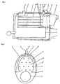
- the boiler shown in the figures for the preparation of Hot water has a water-carrying housing 1, which has a flow connection piece 2, and a return connection piece 3 having.
- baffle 6 In a section below the confluence of the flow connector 2 is a special baffle 6 to form a appropriate chamber provided. This chamber becomes the front limited by a baffle 6 '.
- the guide plate 6 or the chamber has a semi-elliptical, semi-circular or semi-cylindrical Form and encloses the Nachschaltsammlung vom 5 or the condensation Area 13.
- the lower area is of the guide plate 6 to the central longitudinal axis of the housing 1 and Combustion chamber 4 tapers or narrows to a cold water flow from the lower boiler area to those at risk of condensation Reduce area 13.
- the return connector 3 is above a section of the secondary heating surfaces through which very hot flue gases flow 5 is located, or as indicated in FIG. 1, is arranged in the lower region of the housing 1, can on a separate return baffle with the advantage of a smaller one Construction effort and a more uniform temperature distribution in the Boiler interior can be dispensed with.
- the chamber owns Bypass openings 12 through which hot water flows 8 can be made with boiler water from the colder area 9 mix.
- the flow water 10 then has one Temperature which is the mixed temperature of warm boiler water 8 with water from the colder area 9.
- the guide plate 6 extends as shown in FIG. 1, only over a section of the secondary heating surfaces 5, namely over such a section that leads to flue gas extraction 11 is directed towards and the result of the already cooled Flue gases have the lowest temperature and are therefore special is at risk of condensation.
- the target temperature of the flow water is not one shown external control and the amount of heating water from the heating system, comprising pump, mixer, etc. determined.
- the Water quantities of the warm and the cold partial flow result then about the shape of the baffle or this formed chamber and the size of the bypass openings or the Bypnaturequeritese.
- the Cross-sectional area of the bypass openings through a not shown adjustable aperture or the like depending changed from the target temperature of the flow water from the outside be, so that there are optimal flow conditions within of the boiler depending on the respective load let set.
Landscapes
- Engineering & Computer Science (AREA)
- Physics & Mathematics (AREA)
- Thermal Sciences (AREA)
- Chemical & Material Sciences (AREA)
- Combustion & Propulsion (AREA)
- Mechanical Engineering (AREA)
- General Engineering & Computer Science (AREA)
- Heat-Pump Type And Storage Water Heaters (AREA)
- Incineration Of Waste (AREA)
- Chimneys And Flues (AREA)
Description
Unter der Einmündung eines Rücklaufanschlußstutzens werden Rücklaufeinströmbleche oder -kammern ausgebildet, welche im oberen Bereich des Kessels bzw. des Wassermantels eine Kurzschlußströmung vom Rücklauf- zum Vorlaufanschlußstutzen verhindern sollen. Diese Rücklaufeinströmbleche lenken demnach die kalte Rücklaufwasserströmung in den unteren Bereich des Wassermantels bzw. des Kessels. Auf dem weiteren Weg wird das strömende Wasser erwärmt, wobei sich eine thermische Schichtung im Kessel einstellt. Im unteren Bereich des Kessels entspricht die Wassertemperatur in etwa der Rücklauftemperatur hingegen im oberen Bereich der Vorlauftemperatur. Im Bereich der Nachschaltheizflächen liegt die Wassertemperatur unter der Vorlauftemperatur.
Um die geforderten Wirkungen zu erreichen, muß die bekannte Rücklaufeinströmkammer über einen großen Abschnitt der horizontalen Länge des Kessels geführt werden, mit der Folge einer ungleichmäßigeren Temperaturverteilung über das gesamte Kesselvolumen.
- Fig. 1
- eine prinzipielle Darstellung des Kessels zur Aufbereitung von Warmwasser in seitlicher Schnittdarstellung und
- Fig. 2
- eine Querschnittsdarstellung des Kessels längs der Linie A-A aus Fig. 1.
- 1
- Gehäuse
- 2
- Vorlaufanschlußstutzen
- 3
- Rücklaufanschlußstutzen
- 4
- Brennkammer
- 5
- Nachschaltheizflächen
- 6
- Vorlaufleitblech
- 6'
- Vorlaufleitblech zur stirnseitigen Begrenzung der Vorlaufkammer
- 7
- Rücklaufleitblech
- 8
- Warmwasserstrom
- 9
- Kaltwasserstrom
- 10
- Vorlaufwasser
- 11
- Rauchgasabzug
- 12
- Bypaßöffnungen
- 13
- kondensationsgefährderter Bereich
Claims (7)
- Kessel zur Aufbereitung von Warmwasser mit einem wasserführenden Gehäuse (1), enthaltend einen Vor- und Rücklaufanschlußstutzen (2, 3) sowie eine im Gehäuse (1) angeordnete im wesentlichen horizontale Brennkammer (4), welche mit Nachschaltheizflächen (5) in Verbindung steht die von Heizgasen hin zu einem Rauchgasabzug (11) durchströmt werden,
wobei mindestens der Vorlaufanschlußstutzen (2) an der Oberseite des Gehäuses (1) befindlich ist,
wobei sich vom Bereich des Vorlaufanschlußstutzens (2) im Inneren des Gehäuses hin zum Gehäuseboden gerichtet, die Nachschaltheizflächen (5) umgebend, eine Vorlaufkammer erstreckt,
wobei die Vorlaufkammer von einem ersten Vorlaufleitblech (6) gebildet wird, das eine halbzylindrische oder halbelliptische Form hat, und
wobei die Vorlaufkammer im oberen, zum Vorlaufanschlußstutzen (2) gerichteten Abschnitt mindestens eine Bypaßöffnung (12) aufweist, so daß ein Unterschreiten der Taupunkttemperatur im Bereich der Nachschaltheizflächen (5) durch Beeinflussung der Kaltwasserzuströmung im Kesselbetrieb verhinderbar ist,
dadurch gekennzeichnet, daß
die Vorlaufkammer stirnseitig von einem zweiten Vorlaufleitblech (6') begrenzt ist. - Kessel nach Anspruch 1,
dadurch gekennzeichnet, daß
im offenen Bereich der halbzylindrischen oder halbelliptischen Vorlaufkammer diese eine Verengung zur Drosselung der Kaltwasserzufuhr in den kondensatgefährdeten Kammerinnenraum (13) aufweist. - Kessel nach Anspruch 1 oder 2,
dadurch gekennzeichnet, daß
unterhalb eines an der Oberseite des Kessels vorgesehenen Rücklaufanschlußstutzens (3) ein Rücklaufleitblech (7) zur Verhinderung einer thermischen Kurzschlußströmung hin zum Vorlaufanschlußstutzen (2) angeordnet ist. - Kessel nach Anspruch 1 oder 2,
dadurch gekennzeichnet, daß
der Rücklaufanschlußstutzen (3) an der Kesselunterseite angeordnet ist. - Kessel nach einem der vorangegangenen Ansprüche,
dadurch gekennzeichnet, daß
die Querschnittsfläche der mindestens einen Bypaßöffnung (12) veränderbar ist. - Kessel nach einem der vorangegangenen Ansprüche,
dadurch gekennzeichnet, daß
sich die zumindest eine Bypaßöffnung (12) stirnseitig an der Vorlaufkammer für den Zustrom von erwärmtem Wasser hin zum Vorlaufanschlußstutzen (2) befindet. - Kessel nach einem der vorangegangenen Ansprüche,
dadurch gekennzeichnet, daß
sich die Vorlaufkammer über einen zum Rauchgasabzug (11) hin gerichteten Teilabschnitt der Nachschaltheizflächen (5) erstreckt.
Applications Claiming Priority (4)
| Application Number | Priority Date | Filing Date | Title |
|---|---|---|---|
| DE19720456 | 1997-05-15 | ||
| DE19720456 | 1997-05-15 | ||
| DE19724942 | 1997-06-12 | ||
| DE19724942A DE19724942C1 (de) | 1997-05-15 | 1997-06-12 | Kessel zur Aufbereitung von Warmwasser |
Publications (3)
| Publication Number | Publication Date |
|---|---|
| EP0878674A2 EP0878674A2 (de) | 1998-11-18 |
| EP0878674A3 EP0878674A3 (de) | 2000-05-24 |
| EP0878674B1 true EP0878674B1 (de) | 2004-07-14 |
Family
ID=26036582
Family Applications (1)
| Application Number | Title | Priority Date | Filing Date |
|---|---|---|---|
| EP98102442A Expired - Lifetime EP0878674B1 (de) | 1997-05-15 | 1998-02-12 | Kessel zur Aufbereitung von Warmwasser |
Country Status (2)
| Country | Link |
|---|---|
| EP (1) | EP0878674B1 (de) |
| AT (1) | ATE271209T1 (de) |
Family Cites Families (2)
| Publication number | Priority date | Publication date | Assignee | Title |
|---|---|---|---|---|
| DE3502435A1 (de) * | 1985-01-25 | 1986-07-31 | Hans Dr.h.c. 3559 Battenberg Vießmann | Heizungskessel |
| DE29602075U1 (de) | 1996-02-07 | 1996-05-23 | Buderus Heiztechnik Gmbh, 35576 Wetzlar | Heizkessel |
-
1998
- 1998-02-12 EP EP98102442A patent/EP0878674B1/de not_active Expired - Lifetime
- 1998-02-12 AT AT98102442T patent/ATE271209T1/de active
Also Published As
| Publication number | Publication date |
|---|---|
| EP0878674A3 (de) | 2000-05-24 |
| ATE271209T1 (de) | 2004-07-15 |
| EP0878674A2 (de) | 1998-11-18 |
Similar Documents
| Publication | Publication Date | Title |
|---|---|---|
| CH616499A5 (en) | Central heating system with a boiler and an additional heat exchanger for preheating the medium flowing back to the boiler | |
| DE3310023C2 (de) | Vorratswasserheizanlage | |
| DE19854910B4 (de) | Heizkessel | |
| DE3109990A1 (de) | Elektrischer durchlauferhitzer als zusatz-heizeinrichtung fuer zentralheizungsanlagen | |
| EP0122475B1 (de) | Heizanlage | |
| DE3347559A1 (de) | Niedertemperaturheizungskessel, insbesondere fuer mittlere und grosse leistungsbereiche | |
| DE3140821A1 (de) | Vorrichtung zum erwaermen von fluessigkeiten | |
| EP0878674A2 (de) | Kessel zur Aufbereitung von Warmwasser | |
| DE60016819T2 (de) | Heizgerät mit gegossenem, einteiligem Wärmetauscher | |
| DE29602990U1 (de) | Wasserheizer | |
| DE19724942C1 (de) | Kessel zur Aufbereitung von Warmwasser | |
| DE69623834T2 (de) | Wärmetauscher mit universellem Verbrennungsraum und Kondensatablauf | |
| AT406518B (de) | Heizkessel | |
| DE69406207T2 (de) | Kombinierter Brennwertkessel | |
| EP0031571B1 (de) | Heizungskessel | |
| DE2918306C2 (de) | Wärmetauscher für einen Heizkamin | |
| DE3217355A1 (de) | Heizungskessel | |
| DE9105410U1 (de) | Zentralheizungskessel | |
| CH657912A5 (de) | Gasbeheizte kesselanlage. | |
| EP1389719B1 (de) | Wärmeübertrager für Brennwert-Heizgeräte | |
| DE3509887C2 (de) | ||
| DE19528353A1 (de) | Wärmeerzeuger für NT-Betrieb und Verfahren zum Betreiben des Wärmeerzeugers | |
| DE8700127U1 (de) | Vorrichtung zur Einsparung von Energie an Öl-Gas-Heizkesseln | |
| DE3242717A1 (de) | Wasservorwaermer fuer brauchwasser | |
| DE8908459U1 (de) | Vorrichtung zum Erwärmen einer Flüssigkeit, insbesondere Wasserheizer |
Legal Events
| Date | Code | Title | Description |
|---|---|---|---|
| PUAI | Public reference made under article 153(3) epc to a published international application that has entered the european phase |
Free format text: ORIGINAL CODE: 0009012 |
|
| AK | Designated contracting states |
Kind code of ref document: A2 Designated state(s): AT BE CH DE DK ES FI FR GB GR IE IT LI LU MC NL PT SE |
|
| AX | Request for extension of the european patent |
Free format text: AL;LT;LV;MK;RO;SI |
|
| PUAL | Search report despatched |
Free format text: ORIGINAL CODE: 0009013 |
|
| AK | Designated contracting states |
Kind code of ref document: A3 Designated state(s): AT BE CH DE DK ES FI FR GB GR IE IT LI LU MC NL PT SE |
|
| AX | Request for extension of the european patent |
Free format text: AL;LT;LV;MK;RO;SI |
|
| 17P | Request for examination filed |
Effective date: 20000602 |
|
| AKX | Designation fees paid |
Free format text: AT BE CH DE DK ES FI FR GB GR IE IT LI LU MC NL PT SE |
|
| AXX | Extension fees paid |
Free format text: LV PAYMENT 20000704;MK PAYMENT 20000704;RO PAYMENT 20000704;SI PAYMENT 20000704 |
|
| 17Q | First examination report despatched |
Effective date: 20020214 |
|
| GRAP | Despatch of communication of intention to grant a patent |
Free format text: ORIGINAL CODE: EPIDOSNIGR1 |
|
| GRAP | Despatch of communication of intention to grant a patent |
Free format text: ORIGINAL CODE: EPIDOSNIGR1 |
|
| GRAS | Grant fee paid |
Free format text: ORIGINAL CODE: EPIDOSNIGR3 |
|
| GRAA | (expected) grant |
Free format text: ORIGINAL CODE: 0009210 |
|
| AK | Designated contracting states |
Kind code of ref document: B1 Designated state(s): AT BE CH DE DK ES FI FR GB GR IE IT LI LU MC NL PT SE |
|
| AX | Request for extension of the european patent |
Extension state: LV MK RO SI |
|
| PG25 | Lapsed in a contracting state [announced via postgrant information from national office to epo] |
Ref country code: NL Free format text: LAPSE BECAUSE OF FAILURE TO SUBMIT A TRANSLATION OF THE DESCRIPTION OR TO PAY THE FEE WITHIN THE PRESCRIBED TIME-LIMIT Effective date: 20040714 Ref country code: IT Free format text: LAPSE BECAUSE OF FAILURE TO SUBMIT A TRANSLATION OF THE DESCRIPTION OR TO PAY THE FEE WITHIN THE PRE;WARNING: LAPSES OF ITALIAN PATENTS WITH EFFECTIVE DATE BEFORE 2007 MAY HAVE OCCURRED AT ANY TIME BEFORE 2007. THE CORRECT EFFECTIVE DATE MAY BE DIFFERENT FROM THE ONE RECORDED.SCRIBED TIME-LIMIT Effective date: 20040714 Ref country code: IE Free format text: LAPSE BECAUSE OF FAILURE TO SUBMIT A TRANSLATION OF THE DESCRIPTION OR TO PAY THE FEE WITHIN THE PRESCRIBED TIME-LIMIT Effective date: 20040714 Ref country code: GB Free format text: LAPSE BECAUSE OF FAILURE TO SUBMIT A TRANSLATION OF THE DESCRIPTION OR TO PAY THE FEE WITHIN THE PRESCRIBED TIME-LIMIT Effective date: 20040714 Ref country code: FR Free format text: LAPSE BECAUSE OF FAILURE TO SUBMIT A TRANSLATION OF THE DESCRIPTION OR TO PAY THE FEE WITHIN THE PRESCRIBED TIME-LIMIT Effective date: 20040714 Ref country code: FI Free format text: LAPSE BECAUSE OF FAILURE TO SUBMIT A TRANSLATION OF THE DESCRIPTION OR TO PAY THE FEE WITHIN THE PRESCRIBED TIME-LIMIT Effective date: 20040714 |
|
| REG | Reference to a national code |
Ref country code: GB Ref legal event code: FG4D Free format text: NOT ENGLISH |
|
| REG | Reference to a national code |
Ref country code: CH Ref legal event code: EP |
|
| REF | Corresponds to: |
Ref document number: 59811664 Country of ref document: DE Date of ref document: 20040819 Kind code of ref document: P |
|
| REG | Reference to a national code |
Ref country code: IE Ref legal event code: FG4D Free format text: GERMAN |
|
| PG25 | Lapsed in a contracting state [announced via postgrant information from national office to epo] |
Ref country code: SE Free format text: LAPSE BECAUSE OF FAILURE TO SUBMIT A TRANSLATION OF THE DESCRIPTION OR TO PAY THE FEE WITHIN THE PRESCRIBED TIME-LIMIT Effective date: 20041014 Ref country code: GR Free format text: LAPSE BECAUSE OF FAILURE TO SUBMIT A TRANSLATION OF THE DESCRIPTION OR TO PAY THE FEE WITHIN THE PRESCRIBED TIME-LIMIT Effective date: 20041014 Ref country code: DK Free format text: LAPSE BECAUSE OF FAILURE TO SUBMIT A TRANSLATION OF THE DESCRIPTION OR TO PAY THE FEE WITHIN THE PRESCRIBED TIME-LIMIT Effective date: 20041014 |
|
| PG25 | Lapsed in a contracting state [announced via postgrant information from national office to epo] |
Ref country code: ES Free format text: LAPSE BECAUSE OF FAILURE TO SUBMIT A TRANSLATION OF THE DESCRIPTION OR TO PAY THE FEE WITHIN THE PRESCRIBED TIME-LIMIT Effective date: 20041025 |
|
| NLV1 | Nl: lapsed or annulled due to failure to fulfill the requirements of art. 29p and 29m of the patents act | ||
| GBV | Gb: ep patent (uk) treated as always having been void in accordance with gb section 77(7)/1977 [no translation filed] |
Effective date: 20040714 |
|
| PG25 | Lapsed in a contracting state [announced via postgrant information from national office to epo] |
Ref country code: LU Free format text: LAPSE BECAUSE OF NON-PAYMENT OF DUE FEES Effective date: 20050212 |
|
| PG25 | Lapsed in a contracting state [announced via postgrant information from national office to epo] |
Ref country code: MC Free format text: LAPSE BECAUSE OF NON-PAYMENT OF DUE FEES Effective date: 20050228 Ref country code: LI Free format text: LAPSE BECAUSE OF NON-PAYMENT OF DUE FEES Effective date: 20050228 Ref country code: CH Free format text: LAPSE BECAUSE OF NON-PAYMENT OF DUE FEES Effective date: 20050228 Ref country code: BE Free format text: LAPSE BECAUSE OF NON-PAYMENT OF DUE FEES Effective date: 20050228 |
|
| REG | Reference to a national code |
Ref country code: IE Ref legal event code: FD4D |
|
| PLBE | No opposition filed within time limit |
Free format text: ORIGINAL CODE: 0009261 |
|
| STAA | Information on the status of an ep patent application or granted ep patent |
Free format text: STATUS: NO OPPOSITION FILED WITHIN TIME LIMIT |
|
| 26N | No opposition filed |
Effective date: 20050415 |
|
| EN | Fr: translation not filed | ||
| BERE | Be: lapsed |
Owner name: *WOLF G.M.B.H. Effective date: 20050228 |
|
| REG | Reference to a national code |
Ref country code: CH Ref legal event code: PL |
|
| BERE | Be: lapsed |
Owner name: *WOLF G.M.B.H. Effective date: 20050228 |
|
| PG25 | Lapsed in a contracting state [announced via postgrant information from national office to epo] |
Ref country code: PT Free format text: LAPSE BECAUSE OF NON-PAYMENT OF DUE FEES Effective date: 20041214 |
|
| PGFP | Annual fee paid to national office [announced via postgrant information from national office to epo] |
Ref country code: AT Payment date: 20120223 Year of fee payment: 15 |
|
| REG | Reference to a national code |
Ref country code: AT Ref legal event code: MM01 Ref document number: 271209 Country of ref document: AT Kind code of ref document: T Effective date: 20130228 |
|
| PG25 | Lapsed in a contracting state [announced via postgrant information from national office to epo] |
Ref country code: AT Free format text: LAPSE BECAUSE OF NON-PAYMENT OF DUE FEES Effective date: 20130228 |
|
| PGFP | Annual fee paid to national office [announced via postgrant information from national office to epo] |
Ref country code: DE Payment date: 20150429 Year of fee payment: 18 |
|
| REG | Reference to a national code |
Ref country code: DE Ref legal event code: R119 Ref document number: 59811664 Country of ref document: DE |
|
| PG25 | Lapsed in a contracting state [announced via postgrant information from national office to epo] |
Ref country code: DE Free format text: LAPSE BECAUSE OF NON-PAYMENT OF DUE FEES Effective date: 20160901 |