EP0878152B1 - Abgabevorrichtung - Google Patents
Abgabevorrichtung Download PDFInfo
- Publication number
- EP0878152B1 EP0878152B1 EP19980303912 EP98303912A EP0878152B1 EP 0878152 B1 EP0878152 B1 EP 0878152B1 EP 19980303912 EP19980303912 EP 19980303912 EP 98303912 A EP98303912 A EP 98303912A EP 0878152 B1 EP0878152 B1 EP 0878152B1
- Authority
- EP
- European Patent Office
- Prior art keywords
- carriage
- rollers
- product
- width
- carriage means
- Prior art date
- Legal status (The legal status is an assumption and is not a legal conclusion. Google has not performed a legal analysis and makes no representation as to the accuracy of the status listed.)
- Expired - Lifetime
Links
Images


Classifications
-
- A—HUMAN NECESSITIES
- A47—FURNITURE; DOMESTIC ARTICLES OR APPLIANCES; COFFEE MILLS; SPICE MILLS; SUCTION CLEANERS IN GENERAL
- A47F—SPECIAL FURNITURE, FITTINGS, OR ACCESSORIES FOR SHOPS, STOREHOUSES, BARS, RESTAURANTS OR THE LIKE; PAYING COUNTERS
- A47F1/00—Racks for dispensing merchandise; Containers for dispensing merchandise
- A47F1/04—Racks or containers with arrangements for dispensing articles, e.g. by means of gravity or springs
- A47F1/12—Racks or containers with arrangements for dispensing articles, e.g. by means of gravity or springs dispensing from the side of an approximately horizontal stack
- A47F1/125—Racks or containers with arrangements for dispensing articles, e.g. by means of gravity or springs dispensing from the side of an approximately horizontal stack with an article-pushing device
Definitions
- This invention relates to dispensing apparatus according to the preamble of claim 1, see GB-A-1037 805, and a dispensing apparatus kit.
- Gravity feed dispensing apparatuses are well-known for dispensing products.
- One known apparatus simply comprises an inclined chute in which a line of products is arranged. When the forward-most product is removed from the chute, the remaining products shunt forward due to gravity acting upon them.
- One problem associated with such known apparatus is that light products, for example packets of crisps or boxes of women's tights, are restricted from moving forward under gravity by the frictional force existing between them and the chute.
- a spring-loaded pusher plate may be arranged upstream of the products to be dispensed. On removal of the forward-most item from such a chute, the pusher plate urges the remaining products forward. Problems associated with this apparatus is its relatively complicated design and difficulties in selecting an appropriate spring force which is sufficient to urge products forward but does not damage them.
- dispensing apparatus comprising an inclined guide means for receiving a product to be dispensed and a carriage means movable within the guide means, said carriage means comprising a body, said body comprising at its forward end, product contact means for contacting a product to urge it forward, characterised in that said carriage means includes at least two rollers for aiding movement of the carriage means, one of said rollers is spaced from another said roller and in which the axes of the rollers are substantially parallel, and wherein the rollers have a width which is greater that 50% of the width of the carriage means.
- Said carriage means preferably includes containment means for containing a product.
- Said guide means is preferably of channel cross-section. It is preferably made out of a plastics material.
- Said contact means is preferably inclined, suitably rearwardly, preferably at an angle in the range 30° to 75°.
- Said product contact means may comprise a substantially planar member for contacting at least a part of the product.
- Said carriage means preferably includes axle support means for supporting axles of said rollers.
- Said axle support means preferably comprise depending members each of which suitably includes means for retaining an axle.
- Said means may comprise an opening which is suitably arranged to receive an axle.
- Said axle support means is preferably resilient for allowing axles of said rollers to be engaged therewith.
- Said product contact means is preferably a unitary part of a base part of said body which body preferably includes said axle support means which are also preferably a unitary part of said body.
- Said base part preferably extends across substantially the whole width of said carriage means.
- Said rollers may have a width which is greater than 50% preferably 60%, more preferably 70%, especially 80% of the width of the carriage.
- Said rollers are preferably made out of a plastics material.
- Said rollers preferably include axles at each end which are suitably arranged in openings in the body of the carriage means.
- Said body preferably includes at least two, preferably at least three, more preferably at least four openings in which axles of two or more rollers are retained.
- Said rollers are preferably arranged on opposing sides of the centre of gravity of the carriage means.
- Extension means may be provided for increasing the width of a forward end of the carriage means, preferably a product contact means thereof.
- the width of said forward end may suitably be increased with the width of said body and/or the distance between said axle support members suitably remaining the same. This may suitably allow a carriage of one width to be used in a guide means of a larger width.
- Said extension means may be releasably securable to the carriage means.
- Said carriage means may include containment means for containing product.
- said containment means may comprise spaced apart uprights between which product can be placed.
- the width of said body and/or the distance between said axle support members is at least 5cm, preferably at least 8cm, more preferably at least 10cm, especially at least 12cm.
- the width may be less than 40cm, preferably less than 30cm, especially less than 20cm.
- novel carriage means for a dispensing apparatus as described in any statement herein may be manufacdured by forming a member into a channel section and retaining a rotatable member within said section.
- Said member formed into a channel section is preferably made of plastics.
- Said channel section is preferably downwardly open.
- Manufacture of the carriage may include the step of forming said member into a portion which is inclined relative to said channel section.
- Manufacture may also include the step of providing openings in said channel section and engaging portions of said rotatable member in said openings.
- a dispensing apparatus kit comprising a guide means for receiving a product and carriage means as described in any statement herein.
- the product dispensed may be a food or non-food item. It may have a width in the range 2cm to 40cm, preferably 5cm to 30cm, more preferably 5cm to 15cm.
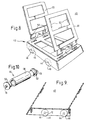
- a dispensing apparatus comprises an inclined chute 4 which comprises a channel cross-section plastics member of a suitable size to accommodate a product 6 to be dispensed.
- a carriage 8 is provided upstream of the product and is arranged to urge the product downwardly towards front end 10 of the chute so that, if the forward-most item 6a is removed from the chute the remaining items 6 are shunted forward so that item 6b becomes the forward-most item.
- carriage 8 comprises a transparent plastics body having a horizontally extending portion 11, from which side members 12 depend. At their forward ends, the side members define angled nose portions 14.
- a pusher plate 16 comprising a planar member is inclined upwardly from a forward end of portion 10 at the same angle as that defined by said nose portions.
- rollers 20 are mounted between the side members 12 with their axes extending parallel to one another.
- the rollers include stub axles 19 at opposite ends which are a unitary part of the rollers.
- the rollers may be made from a single cylindrical piece of plastics material by removing annular bands of material from each end to define the axles.
- the stub axles 19 are rotatable within openings drilled in the side members 12.
- nose portions 14 and pusher plate 16 may be changed depending on the nature of the product being dispensed. For example, if packets of crisps are being dispensed, the gap defined below the pusher plate 16 may be made narrower to prevent the packets being caught up in the gap.
- the carriage shown in the figures may easily be adapted to fit wider chutes.
- the pusher plate 16 may be made wider or, alternative, an extension piece may be secured to an existing pusher plate.
- the body of the carriage may be made out of a single piece of plastics material by bending the material to define the side members 12 and pusher plate 16.
- Polyester glycol (PETG) material is preferred since it has high impact, low moisture absorption and can withstand temperatures of down to -50°C without becoming appreciable brittle.
- Rollers 20 may be manufactured as described above and are preferably made from natural acetal which is relatively dense and suitable for use in cold storage applications. The rollers may be secured to the body by slightly urging side members 12 apart and engaging stub axles 19 in openings drilled in the side members.
- a carriage 40 comprise a plastics injection moulded body 42 which has downwardly open slots 44 for receiving a pair of rollers 46.
- a roller 46 is shown in figure 10 and it comprises a tubular body 48 in which steel rods (not shown) are inserted for ballast purposes.
- a pair of end caps 50 which incorporate stub axles 19 are secured within respective ends of the tubes.
- the body 42 includes a front pair 54 and a rear pair 56 of slots which are arranged to engage respective pairs of projections 58 which depend from respective uprights 60 for securing the uprights to the body 42.
- the uprights When in position, the uprights define a gap into which additional products may be placed, thereby to maximise the amount of product stored in the chute 4 of the apparatus.
- the front upright 60 includes lugs 62 for retaining merchandising tickets (or the like).
Landscapes
- Chutes (AREA)
Claims (8)
- Abgabevorrichtung, die eine geneigte Leiteinrichtung (4), die ein abzugebendes Erzeugnis (6) aufnimmt, sowie eine Wageneinrichtung (8), die in der Leiteinrichtung (4) bewegt werden kann, umfasst, wobei die Wageneinrichtung (8) einen Körper (16) umfasst und der Körper an seinem vorderen Ende eine Erzeugnis-Kontakteinrichtung (16) umfasst, die mit einem Erzeugnis (6) in Kontakt kommt, um es vorwärts zu drücken, dadurch gekennzeichnet, dass die Wageneinrichtung (8) wenigstens zwei Rollen (20) enthält, die Bewegung der Wageneinrichtung unterstützen, wobei eine der Rollen (20) von der anderen der Rollen (20) beabstandet ist und die Achsen der Rollen (20) im Wesentlichen parallel sind und wobei die Rollen (20) eine Breite haben, die größer ist als 50% der Breite der Wageneinrichtung (8).
- Vorrichtung nach Anspruch 1, wobei die Wageneinrichtung eine Aufnahmeeinrichtung zum Aufnehmen eines Erzeugnisses (6) enthält.
- Vorrichtung nach Anspruch 1 oder Anspruch 2, wobei die Leiteinrichtung (4) rinnenförmigen Querschnitt hat.
- Vorrichtung nach einem der vorangehenden Ansprüche, wobei die Wageneinrichtung (8) Achsentrageeinrichtungen zum Tragen von Achsen der Rollen enthält.
- Vorrichtung nach einem der vorangehenden Ansprüche, wobei die Erzeugnis-Kontakteinrichtung (16) integraler Teil eines Unterteils des Körpers ist, und der Körper Achsentrageeinrichtungen enthält, die ebenfalls integraler Teil desselben sind.
- Vorrichtung nach einem der vorangehenden Ansprüche, wobei die Rollen (20) aus einem Kunststoffmaterial bestehen.
- Vorrichtung nach einem der vorangehenden Ansprüche, wobei eine Erweiterungseinrichtung zur Vergrößerung der Breite eines vorderen Endes der Wageneinrichtung (8) vorhanden ist.
- Abgabevorrichtungs-Bausatz, der eine Leiteinrichtung (4) zum Aufnehmen eines Erzeugnisses (6) und eine Wageneinrichtung (8) nach einem der Ansprüche 1 bis 7 umfasst.
Applications Claiming Priority (2)
| Application Number | Priority Date | Filing Date | Title |
|---|---|---|---|
| GBGB9709961.8A GB9709961D0 (en) | 1997-05-17 | 1997-05-17 | Dispensing apparatus |
| GB9709961 | 1997-05-17 |
Publications (2)
| Publication Number | Publication Date |
|---|---|
| EP0878152A1 EP0878152A1 (de) | 1998-11-18 |
| EP0878152B1 true EP0878152B1 (de) | 2003-04-16 |
Family
ID=10812420
Family Applications (1)
| Application Number | Title | Priority Date | Filing Date |
|---|---|---|---|
| EP19980303912 Expired - Lifetime EP0878152B1 (de) | 1997-05-17 | 1998-05-18 | Abgabevorrichtung |
Country Status (3)
| Country | Link |
|---|---|
| EP (1) | EP0878152B1 (de) |
| DE (1) | DE69813366D1 (de) |
| GB (2) | GB9709961D0 (de) |
Families Citing this family (5)
| Publication number | Priority date | Publication date | Assignee | Title |
|---|---|---|---|---|
| GB2346874A (en) * | 1999-02-19 | 2000-08-23 | Barkston Plastics Display Limi | Dispensing apparatus with pivotable support means |
| DE29912507U1 (de) * | 1999-07-16 | 1999-10-07 | Linde Ag, 65189 Wiesbaden | Zubehör für eine Rutschauslage |
| DE102012111751A1 (de) * | 2012-12-04 | 2014-06-05 | Rickard Nilsson | Laufkörper für eine auf Waren wirkende Drückeinrichtung eines Rutschregales sowie Drückeinrichtung |
| DE102014101755A1 (de) * | 2014-02-12 | 2015-08-13 | Rickard Nilsson | Laufkörper für eine auf Waren wirkende Drückeinrichtung eines Rutschregales sowie Drückeinrichtung |
| DE102020121737A1 (de) * | 2020-08-19 | 2022-02-24 | Rickard Nilsson | Drückvorrichtung zum Ausüben einer Druckkraft gegen Waren einer Warenpräsentationsvorrichtung |
Family Cites Families (8)
| Publication number | Priority date | Publication date | Assignee | Title |
|---|---|---|---|---|
| GB1037805A (en) * | 1963-07-04 | 1966-08-03 | John Joseph Parkes | Apparatus for storing, dispensing and displaying goods |
| DE1529741A1 (de) * | 1966-10-14 | 1970-07-09 | Continental Gummi Werke Ag | Warenlager |
| US4008828A (en) * | 1975-09-29 | 1977-02-22 | Branchaud Jean Marie | Newspaper vending machine |
| DE3013866C2 (de) * | 1980-04-10 | 1984-01-12 | Allit-Plastikwerk Kimnach & Co, 6550 Bad Kreuznach | Vorrichtung zum Deponieren einer Vielzahl gleichförmiger Waren und zum Darbieten der Waren als Einzelstücke für die Entnahme |
| US4386710A (en) * | 1981-09-11 | 1983-06-07 | Dauman Displays, Inc. | Combination point-of-sale display and dispenser device |
| FR2578734B1 (fr) * | 1985-03-18 | 1988-02-26 | Dollfus Mieg Et Cie | Presentoir pour objets de forme generale cylindrique en particulier pour bobines de fil |
| US4651883A (en) * | 1985-07-29 | 1987-03-24 | Leggett & Platt, Incorporated | Gravity feed pusher merchandiser |
| FR2720611B1 (fr) * | 1994-06-02 | 1996-08-30 | Caddie Atel Reunis | Dispositif de présentation d'articles. |
-
1997
- 1997-05-17 GB GBGB9709961.8A patent/GB9709961D0/en active Pending
-
1998
- 1998-05-16 GB GB9810476A patent/GB2325221B/en not_active Expired - Fee Related
- 1998-05-18 DE DE69813366T patent/DE69813366D1/de not_active Expired - Lifetime
- 1998-05-18 EP EP19980303912 patent/EP0878152B1/de not_active Expired - Lifetime
Also Published As
| Publication number | Publication date |
|---|---|
| DE69813366D1 (de) | 2003-05-22 |
| GB9709961D0 (en) | 1997-07-09 |
| GB2325221A (en) | 1998-11-18 |
| GB9810476D0 (en) | 1998-07-15 |
| GB2325221B (en) | 2001-02-21 |
| EP0878152A1 (de) | 1998-11-18 |
Similar Documents
| Publication | Publication Date | Title |
|---|---|---|
| US5385399A (en) | Document storage and display cabinet | |
| US5695074A (en) | Gravity feed bottle display and dispensing rack | |
| CA1189034A (en) | Storage means for use in a vending machine | |
| US9096408B2 (en) | Clam shell bag dispenser | |
| EP0189693A1 (de) | Automatischer Apparat zum direkten Beladen weicher Kekse | |
| US4239099A (en) | Automatic forward-feed shelf | |
| WO1991015141A1 (en) | Multi-package adjustable shelf display dispenser | |
| GB1437516A (en) | Paper roll holding and dispensing device | |
| JPH0636774B2 (ja) | 商品陳列ケース | |
| CA2300920A1 (en) | Shelf assembly having a u-shaped pusher for urging products forward | |
| PL206456B1 (pl) | Urządzenie do przesuwania towaru na powierzchniach ekspozycyjnych | |
| EP0878152B1 (de) | Abgabevorrichtung | |
| US4238022A (en) | Automatic forward-feed shelf | |
| GB2349075A (en) | Holder for sheet-form articles | |
| ZA889022B (en) | An automatic dispenser for cylindrical commodities,in particular packets of coin | |
| US5516003A (en) | Multiple choice vending machine for newspapers and the like | |
| TW338143B (en) | Coin dispensing apparatus | |
| US20020140328A1 (en) | Storage assembly for modules of varying sizes and improved shelving therefor | |
| US4386710A (en) | Combination point-of-sale display and dispenser device | |
| US20060016736A1 (en) | Stand for mail sorting and other applications | |
| AU3820502A (en) | System for conveying a selected product to a collection compartment in automatic vending machines | |
| AU8315898A (en) | Apparatus for sorting individual pieces | |
| EP1029475A2 (de) | Abgabevorrichtung | |
| AU654213B2 (en) | Display and dispensing of merchandise | |
| US5483877A (en) | Cassette stacker/stamper |
Legal Events
| Date | Code | Title | Description |
|---|---|---|---|
| PUAI | Public reference made under article 153(3) epc to a published international application that has entered the european phase |
Free format text: ORIGINAL CODE: 0009012 |
|
| AK | Designated contracting states |
Kind code of ref document: A1 Designated state(s): DE ES FR IE IT NL SE |
|
| AX | Request for extension of the european patent |
Free format text: AL;LT;LV;MK;RO;SI |
|
| RIN1 | Information on inventor provided before grant (corrected) |
Inventor name: JOANNA STEEL Inventor name: PETER FARRAR |
|
| 17P | Request for examination filed |
Effective date: 19990518 |
|
| AKX | Designation fees paid |
Free format text: AT BE CH CY DE DK ES LI |
|
| RBV | Designated contracting states (corrected) |
Designated state(s): DE ES FR IE IT NL SE |
|
| RAP1 | Party data changed (applicant data changed or rights of an application transferred) |
Owner name: BARTRUX LIMITED |
|
| 17Q | First examination report despatched |
Effective date: 20011130 |
|
| GRAH | Despatch of communication of intention to grant a patent |
Free format text: ORIGINAL CODE: EPIDOS IGRA |
|
| GRAH | Despatch of communication of intention to grant a patent |
Free format text: ORIGINAL CODE: EPIDOS IGRA |
|
| GRAA | (expected) grant |
Free format text: ORIGINAL CODE: 0009210 |
|
| AK | Designated contracting states |
Designated state(s): DE ES FR IE IT NL SE |
|
| PG25 | Lapsed in a contracting state [announced via postgrant information from national office to epo] |
Ref country code: NL Free format text: LAPSE BECAUSE OF FAILURE TO SUBMIT A TRANSLATION OF THE DESCRIPTION OR TO PAY THE FEE WITHIN THE PRESCRIBED TIME-LIMIT Effective date: 20030416 Ref country code: IT Free format text: LAPSE BECAUSE OF FAILURE TO SUBMIT A TRANSLATION OF THE DESCRIPTION OR TO PAY THE FEE WITHIN THE PRESCRIBED TIME-LIMIT;WARNING: LAPSES OF ITALIAN PATENTS WITH EFFECTIVE DATE BEFORE 2007 MAY HAVE OCCURRED AT ANY TIME BEFORE 2007. THE CORRECT EFFECTIVE DATE MAY BE DIFFERENT FROM THE ONE RECORDED. Effective date: 20030416 Ref country code: FR Free format text: LAPSE BECAUSE OF FAILURE TO SUBMIT A TRANSLATION OF THE DESCRIPTION OR TO PAY THE FEE WITHIN THE PRESCRIBED TIME-LIMIT Effective date: 20030416 |
|
| PG25 | Lapsed in a contracting state [announced via postgrant information from national office to epo] |
Ref country code: IE Free format text: LAPSE BECAUSE OF NON-PAYMENT OF DUE FEES Effective date: 20030519 |
|
| REF | Corresponds to: |
Ref document number: 69813366 Country of ref document: DE Date of ref document: 20030522 Kind code of ref document: P |
|
| REG | Reference to a national code |
Ref country code: IE Ref legal event code: FG4D |
|
| PG25 | Lapsed in a contracting state [announced via postgrant information from national office to epo] |
Ref country code: SE Free format text: LAPSE BECAUSE OF FAILURE TO SUBMIT A TRANSLATION OF THE DESCRIPTION OR TO PAY THE FEE WITHIN THE PRESCRIBED TIME-LIMIT Effective date: 20030716 |
|
| PG25 | Lapsed in a contracting state [announced via postgrant information from national office to epo] |
Ref country code: DE Free format text: LAPSE BECAUSE OF FAILURE TO SUBMIT A TRANSLATION OF THE DESCRIPTION OR TO PAY THE FEE WITHIN THE PRESCRIBED TIME-LIMIT Effective date: 20030717 |
|
| NLV1 | Nl: lapsed or annulled due to failure to fulfill the requirements of art. 29p and 29m of the patents act | ||
| PG25 | Lapsed in a contracting state [announced via postgrant information from national office to epo] |
Ref country code: ES Free format text: LAPSE BECAUSE OF FAILURE TO SUBMIT A TRANSLATION OF THE DESCRIPTION OR TO PAY THE FEE WITHIN THE PRESCRIBED TIME-LIMIT Effective date: 20031030 |
|
| PLBE | No opposition filed within time limit |
Free format text: ORIGINAL CODE: 0009261 |
|
| STAA | Information on the status of an ep patent application or granted ep patent |
Free format text: STATUS: NO OPPOSITION FILED WITHIN TIME LIMIT |
|
| REG | Reference to a national code |
Ref country code: IE Ref legal event code: MM4A |
|
| 26N | No opposition filed |
Effective date: 20040119 |
|
| EN | Fr: translation not filed |