EP0877209A2 - Belüftungsvorrichtung für ein Gebäude - Google Patents
Belüftungsvorrichtung für ein Gebäude Download PDFInfo
- Publication number
- EP0877209A2 EP0877209A2 EP98108272A EP98108272A EP0877209A2 EP 0877209 A2 EP0877209 A2 EP 0877209A2 EP 98108272 A EP98108272 A EP 98108272A EP 98108272 A EP98108272 A EP 98108272A EP 0877209 A2 EP0877209 A2 EP 0877209A2
- Authority
- EP
- European Patent Office
- Prior art keywords
- building
- air
- ventilation
- duct
- pressure
- Prior art date
- Legal status (The legal status is an assumption and is not a legal conclusion. Google has not performed a legal analysis and makes no representation as to the accuracy of the status listed.)
- Granted
Links
Images

Classifications
-
- E—FIXED CONSTRUCTIONS
- E04—BUILDING
- E04F—FINISHING WORK ON BUILDINGS, e.g. STAIRS, FLOORS
- E04F17/00—Vertical ducts; Channels, e.g. for drainage
- E04F17/04—Air-ducts or air channels
-
- F—MECHANICAL ENGINEERING; LIGHTING; HEATING; WEAPONS; BLASTING
- F24—HEATING; RANGES; VENTILATING
- F24F—AIR-CONDITIONING; AIR-HUMIDIFICATION; VENTILATION; USE OF AIR CURRENTS FOR SCREENING
- F24F11/00—Control or safety arrangements
- F24F11/0001—Control or safety arrangements for ventilation
-
- F—MECHANICAL ENGINEERING; LIGHTING; HEATING; WEAPONS; BLASTING
- F24—HEATING; RANGES; VENTILATING
- F24F—AIR-CONDITIONING; AIR-HUMIDIFICATION; VENTILATION; USE OF AIR CURRENTS FOR SCREENING
- F24F3/00—Air-conditioning systems in which conditioned primary air is supplied from one or more central stations to distributing units in the rooms or spaces where it may receive secondary treatment; Apparatus specially designed for such systems
- F24F3/044—Systems in which all treatment is given in the central station, i.e. all-air systems
-
- F—MECHANICAL ENGINEERING; LIGHTING; HEATING; WEAPONS; BLASTING
- F24—HEATING; RANGES; VENTILATING
- F24F—AIR-CONDITIONING; AIR-HUMIDIFICATION; VENTILATION; USE OF AIR CURRENTS FOR SCREENING
- F24F7/00—Ventilation
- F24F7/04—Ventilation with ducting systems, e.g. by double walls; with natural circulation
- F24F7/06—Ventilation with ducting systems, e.g. by double walls; with natural circulation with forced air circulation, e.g. by fan positioning of a ventilator in or against a conduit
-
- F—MECHANICAL ENGINEERING; LIGHTING; HEATING; WEAPONS; BLASTING
- F24—HEATING; RANGES; VENTILATING
- F24F—AIR-CONDITIONING; AIR-HUMIDIFICATION; VENTILATION; USE OF AIR CURRENTS FOR SCREENING
- F24F11/00—Control or safety arrangements
- F24F11/0001—Control or safety arrangements for ventilation
- F24F2011/0002—Control or safety arrangements for ventilation for admittance of outside air
- F24F2011/0004—Control or safety arrangements for ventilation for admittance of outside air to create overpressure in a room
-
- F—MECHANICAL ENGINEERING; LIGHTING; HEATING; WEAPONS; BLASTING
- F24—HEATING; RANGES; VENTILATING
- F24F—AIR-CONDITIONING; AIR-HUMIDIFICATION; VENTILATION; USE OF AIR CURRENTS FOR SCREENING
- F24F2110/00—Control inputs relating to air properties
- F24F2110/40—Pressure, e.g. wind pressure
-
- Y—GENERAL TAGGING OF NEW TECHNOLOGICAL DEVELOPMENTS; GENERAL TAGGING OF CROSS-SECTIONAL TECHNOLOGIES SPANNING OVER SEVERAL SECTIONS OF THE IPC; TECHNICAL SUBJECTS COVERED BY FORMER USPC CROSS-REFERENCE ART COLLECTIONS [XRACs] AND DIGESTS
- Y02—TECHNOLOGIES OR APPLICATIONS FOR MITIGATION OR ADAPTATION AGAINST CLIMATE CHANGE
- Y02B—CLIMATE CHANGE MITIGATION TECHNOLOGIES RELATED TO BUILDINGS, e.g. HOUSING, HOUSE APPLIANCES OR RELATED END-USER APPLICATIONS
- Y02B30/00—Energy efficient heating, ventilation or air conditioning [HVAC]
- Y02B30/70—Efficient control or regulation technologies, e.g. for control of refrigerant flow, motor or heating
Definitions
- the invention relates to a building with at least one with the outer Main ventilation duct and air connection at least one distribution channel, which on the one hand with the at least a main ventilation duct and the other with rooms in the building Air transfer connection is made, the rooms in turn with the outer Stand in the vicinity of the building in an air transfer connection.
- the well-being of people in a building depends among other things also depends on whether there is a basic possibility in The rooms of the building open the windows to allow fresh air into the room to flow. Especially in spring it increases the feeling of life, when, after the long winter, you can finally open again Window can work.
- opening the windows is only for high-rise buildings possible under very restricted conditions, since there are tall buildings Set extreme pressure / suction conditions on a regular basis external wind currents and, on the other hand, due to internal thermals are conditional.
- the outer part of the facade was therefore finished with a Variety of motorized flaps provided depending on opened and closed by a control unit from the wind direction can be.
- the one from the pending Wind generated pressure on the windward side of the building in the gap penetrate between the inner and outer facade part, in this Spread the space around the entire building, and so the At least the pressure difference between the windward side and the lee side of the building significantly reduce.
- this measure did not work for everyone Wind strengths the desired success, so that the doors additionally with Servomotors have been equipped to support the opening movement.
- the motorized flaps and the door servo motors To be able to ensure even in the event of fire must be fulfilled the fire protection regulations a correspondingly dimensioned emergency generator be provided.
- Double facades also have the disadvantage that the Air between the inner and outer part of the facade Warmed up in direct sunlight before entering the rooms of the building is sucked. This heat input is particularly evident in the summer months perceived as unpleasant and makes the use of additional Cooling devices required.
- the high-rise buildings require prior art and in particular their ventilation systems have significant architectural, constructive and control measures, around which the People staying in buildings offer a pleasant indoor climate can.
- This task is achieved in a building of the generic type solved that one assigned to the at least one main ventilation duct Ventilation device for creating and / or maintaining a Ventilation pressure is provided, the value of which is greater than the value of in the external environment prevailing pressure.
- Buildings are therefore overpressured by means of the ventilation device, that to an air flow from the at least one main ventilation duct via the at least one distribution channel into the rooms and from there leads directly into the external environment.
- the value of the pressure difference between the internal pressure of the building and the ambient pressure for example between 10 Pa and 80 Pa, preferably about 30 Pa, be.
- the ventilation device by temporarily increasing the delivery rate ensures that the Total pressure is stabilized to the pressure value intended for the corridor. If the door is closed again, the internal pressure of the room gradually drops back to one between the field pressure and the ambient pressure lying pressure value.
- Ventilation device predetermined air flow direction of the corridors through the rooms towards the outside environment are of particular importance to.
- the vast majority of fires occur in the Clear a building. If smoke develops in connection with the fire, this is the smoke in the building according to the invention pressed directly out of the room into the outside environment and not about in the hallways of the building. Can escape from people the burning room some smoke in the hallway, so this is over the neighboring Clear the hall again and continue into the outside environment promoted.
- the building according to the invention is therefore smoke-free the escape routes ensured.
- a control unit can be provided.
- these pressure sensors can, for example, change the prevailing in the external environment Pressure can be captured by either the general weather conditions (High pressure area, low pressure area) or of the respective wind situation (dynamic wind pressure). This can ensure, for example that the internal pressure is also on the windward side of the building this building has a higher value than the external ambient pressure including wind pressure.
- the building is divided into a plurality of ventilation sectors, to which at least one main ventilation duct is assigned.
- the building is divided into a plurality of ventilation sectors, to which at least one main ventilation duct is assigned.
- Through ventilation sectors separated in the vertical direction can decrease especially with high-rise buildings with increasing height stationary ambient air pressure can be reacted to.
- In the horizontal direction separate ventilation sectors make it possible to wind and wind the lee side of the building with a different overpressure too act upon.
- the device for changing the air passage cross section a Has a non-return device, so can, for example, on gusts of wind coming up the windward side of the building, an air leak from the external environment in the room or from the room in the distribution channel at least difficult, if not completely prevented.
- the at least one distribution channel be formed by a hallway of the building.
- the at least one distribution channel from a separate distribution shaft is formed.
- Both can also Solutions are used in parallel, for example normal ones Offices are supplied with fresh air via the corridor assigned to them, while a conference or meeting room accessible from the same hallway Fresh air supplied via a separate distributor shaft becomes.
- the distributor shaft solution is structurally minor more complex, but has the advantage of a more even distribution the fresh air. So when it comes to ventilating open-plan offices Advise the use of distribution shafts.
- the distribution shaft can both in a ceiling cavity and in a floor cavity arranged, or be formed by these. At the ends of the distribution shafts For example, conventional swirl outlets can be arranged be.
- the outer window unit of the box window advantageously with a baffle plate can be formed, for example, with an all-round Air gap is formed.
- the inner window unit the box window is opened, so the queue is a strong Winds from the person opening the window in the form of a comparatively weak draft is noticed, so that it sensibly the outer window unit won't open. But even if they are the outer box window unit also opens, this leads as described above not to the breakdown of the function of the entire ventilation system, but the resulting strong draft has only on this one Space adverse effects.
- At least one Main ventilation duct a duct section running through the ground having. Because the soil usually has a higher temperature in winter than the outside environment and usually lower in summer Temperature than the external environment, the temperature in the Buildings sucked air in the duct section running through the ground warmed in winter and cooled in summer. Thus, the in Air sucked into the building can be used to air-condition the building. On the one hand, this leads to a reduction in heating and cooling energy and thus the associated costs. On the other hand, it enables air conditioning of the building without the use of noisy or even with CFCs (chlorofluorocarbons) or other polluting substances Fabrics working air conditioning.
- CFCs chlorofluorocarbons
- the air conditioning effect can be further increased if necessary be that at least one channel section running through the ground a heat exchanger is assigned. Should the air conditioning unexpectedly through the earth, contrary to expectations, this can happen be compensated for by having at least one main ventilation duct assigns a heating device and / or a cooling device.
- the above-mentioned air conditioning effect is particularly the case with low buildings of interest, for example single family houses with up to three floors including the attic.
- Such buildings will be like for example in the United States is common, recently also increasingly in Europe in wood or Lightweight construction created. Because with these designs there is no or considerably less Masonry is used compared to these buildings Stone houses made, for example, of bricks and similar building materials are created, a significantly lower heat storage capacity. This has in the summer that they are not even able to to compensate for temperature fluctuations during the day or at least weaken. To compensate for this, unpleasant for the residents Effects come from buildings constructed from lightweight or wooden structures increasingly use air conditioning systems. In addition, the cool above discussed timber or lightweight buildings because of their smaller size thermal buffering capacity in winter quickly, which is due to increased Heating must be adjusted.
- the air drawn in is cooled by the soil, while in winter is heated.
- the heat exchange is enabled alone by correspondingly long measurement of the through the soil running line section the respective conditions on Location are taken into account. For example, one comes when the line section can be laid through the groundwater with a relatively short distance, while with gravel the line section comparatively long.
- the number and length of the pipe sections running through the ground depend on the respective geological conditions.
- the line sections can also be in components, such as. Foundations, bored piles, floor slabs or external walls with earth contact if this is done for technical or economic reasons Reasons.
- the at least one main ventilation duct a throttle device is assigned, which is used, if necessary to counteract the build-up of too high aeration pressure.
- the ventilation device and the throttle device can be of one and the same device, for example an air screw arrangement, those in the pressure mode as a fan and in the throttle mode as Turbine works, so that the ventilation device even in throttle mode can be used to generate electricity.
- a throttle valve is arranged in the at least one main ventilation duct which makes it possible to restrict the air supply into the building or / and to substantially completely prevent it.
- the ventilation device can be in a service area of the building be arranged, for example in the basement or a service floor of the Building.
- the main ventilation ducts in particular their riser sections, can be formed by separate shafts of the building or can be arranged in separate shafts of the building, which are used exclusively for supply purposes. In addition to ventilating the building, these shafts can also be used to run cables for electricity, water and the like.
- the cross-sectional area of a main ventilation duct can be at most 20 m 2 , preferably at most 10 m 2 . It must be optimized depending on the size of the building, the desired air flow speed and the available space.
- the electrical energy required to operate the ventilation device can be easily done during the day using a photovoltaic system to be provided.
- This variant has the additional Advantage of simplifying the control of the ventilation device because increased solar radiation not only the need for ventilation, but also the amount of electrical energy provided by the photovoltaic system increases. So there is always an adequate energy supply for the Ventilation device ensured.
- At least one main ventilation duct each if desired, a whole series of further devices can be assigned can.
- a dust or / and Pollen filter may be provided.
- a humidifier be provided. Yes you could to create a pleasant indoor climate even think about scenting the sucked air.
- a temperature sensor can be located in the at least one main ventilation duct provided for detecting the temperature of the intake air be.
- the temperature signal provided by this temperature sensor can be supplied by the control unit when setting the in the building Air volume are taken into account.
- Neglecting the specific conditions of individual buildings can be said in general terms that with the ventilation device according to the invention achievable air conditioning effect compared to the pure Ventilation of the building is the more important, the lower the building is.
- the invention achieves its ventilation greatest efficiency, however, where the requirements of building regulations and the like by the overpressure ventilation system according to the invention can be easily met while building them State of the art so far only through the use of complex technology could be met. As a rule, this is the case for high-rise buildings with a Height of 50 m and more the case.
- the invention relates according to a further aspect, a ventilation device for a Building according to the invention, which has at least one main ventilation duct with a channel section running through the ground, at least a fan arranged in the main ventilation duct, and a control unit to control the operation of the fan.
- This the Ventilation device in the foreground for air conditioning is mainly for use in lower buildings, for example Single-family houses, designed. However, it is also possible to use them in higher Buildings and high-rise buildings.
- Advantages are on the above discussion of the building according to the invention referred.
- the invention relates to a kit for an inventive Ventilation device.
- the ventilation device according to the invention preferably at low Buildings, such as single family houses, both in an existing one Buildings can be retrofitted as well as in the design of a new building.
- the owners are lower buildings not only in the construction of new buildings, but also in the Retrofitting of finished buildings usually strives, as many as possible Perform work in-house to cover the cost of retrofitting or to keep the new building as low as possible.
- the kit according to the invention which gives them the Construction of the ventilation device according to the invention required components coordinated and put together in one package.
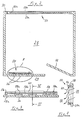
- a building generally designated 10 is shown, the a ventilation system 12 is equipped.
- the ventilation system 12 is in three ventilation sectors arranged one above the other in the vertical direction V. 14A, 14B and 14C split.
- Each of the ventilation sectors 14A to 14C three of the floors 1F to 9F of the building are assigned.
- the ventilation sectors 14A to 14C are essentially identical. Therefore, in the following, for the sake of simplicity, only the construction of the ventilation sector 14A, the main ventilation duct assigned to it 16A and the other associated with this ventilation sector 14A Devices are explained.
- the main ventilation duct 16A has a substantially vertical one Rise section 16Aa and a suction section 16Ab. in the illustrated embodiment passes through the suction section 16Ab the ground 18, causing the sucked air due to the heat exchange warmed with the soil 18 in winter and cooled in summer becomes.
- the efficiency of heat exchange between intake air and Soil 18 can be used by using a suction section 16Ab Heat exchanger 20 can still be increased.
- the building 10 is used for ventilation in its interior pressurized with the centrally supplied fresh air through the hallways into the rooms and further back into the outside environment presses.
- the building 10 according to the invention is therefore ventilated by inside out, as exemplified by the ventilation of the 5F floor curved arrows is indicated.
- the pressure inside the building in particular the pressure P1 prevailing in the corridors 24 is always a predetermined one Pressure difference ⁇ P above that prevailing in the external environment U.
- Pressure P2 is, of course, fluctuations in Pressure difference ⁇ P can be tolerated within certain limits.
- the pressure difference ⁇ P is preferably about 30 Pa.
- Pressure sensors 32 arranged.
- Pressure sensors (not shown) may be provided.
- the pressure signals from the pressure sensors 32 are sent to a control unit 34 passed, which checks whether for the individual ventilation sectors 14A to 14C the pressure difference ⁇ P within the specified control range of, for example, ⁇ 10 Pa. If the thermal pumping action F in one of the riser sections 16A to 16C to maintain the desired one If the pressure difference ⁇ P is insufficient, the control unit 34 sets a blower 36A, 36B assigned to the respective main ventilation duct or 36C in operation to maintain the overall production rate at one the desired pressure difference ⁇ P sufficient value. In contrast, should the thermal due to extreme thermal conditions Delivery rate F to excessive pressure in the building 10 control unit 34 controls throttle valves 38A or 38B or 38C, which lead to a corresponding reduction in the production rate.
- Blowers 36A to 36C can also be used to reduce the delivery rate, for example by using them as a turbine and a part convert the thermal output into electrical power, or by they are even operated in the counterflow direction.
- the electrical energy required to operate the fans 36A to 36C is in the embodiment shown in Figure 1 during the day a photovoltaic system 37 provided. Of course, this can be done in the Facade of building 10 integrated or on the roof of building 10 be arranged. Since both the ventilation requirement and the assigned one required to drive the fans 36A to 36C as well as the electrical power supplied by the photovoltaic system 37 with increasing Sun exposure can increase, the blower can be activated 36A to 36C can at least be simplified since there is always sufficient Energy supply to the blowers is ensured. At best it can such a control can even be completely dispensed with; the "Control" of the blowers is then left solely to the sun.
- the main ventilation ducts 16A to 16C can also be a central one Cooling or heating unit 40 may be assigned so that the intake air before entering the work or living area of building 10 Temperatures can be brought up that differ from those in the building 10 people who are staying are perceived as pleasant. With help (not decentralized heating or cooling devices in rooms 28 and the corridors 24 can then still individual temperature adjustments be made.
- the ventilation system 12 enables Introduction of air heated by external heat sources.
- the building 10 has a winter garden 42, in which the air heats up due to solar radiation S.
- the warmed Air can in the case of need via a flap arrangement 44 in the Rising section 16Aa of the main ventilation duct 16A are introduced.
- the Operation of the flap assembly 44 can be decentralized, i.e. especially independently of the control unit 34, for example thermostatically controlled. This ensures that the supply of additional air quantities in the ventilation system does not impair its function, because the pressure increase caused by the additional air volumes in the Corridors and rooms is detected by the pressure sensors 32 and pulls one corresponding reduction in the delivery rate through the corresponding main ventilation duct after itself.
- flap arrangement 44 corresponding flap arrangements between the winter garden 42 and the main ventilation ducts 16B and 16C of the other ventilation sectors 14B and 14C can be provided.
- Additional external heat sources are provided, for example, in the building Commercial kitchens or laundries are considered, in which case the additional use of filter arrangements or heat exchangers is recommended.
- FIG. 1 can also in the Main ventilation ducts 16A, 16B and 16C filter arrangements, for example Dust and pollen filters can be provided.
- Dust and pollen filters can be provided.
- the suction Humidified air and / or mixed with fragrances in order for a to ensure a pleasant indoor climate.
- the ventilation system 12 is in three ventilation sections 14A to 14C arranged vertically one above the other divided.
- the pressure P2 prevailing in the external environment U increases with increasing Decreases above ground.
- ⁇ P is therefore sufficient in the ventilation section 14A a correspondingly lower internal pressure P1 than in the ventilation section 14C.
- the external ambient pressure P2 is also affected by the Influenced wind conditions. For example, there is on the windward side of the building 10 has a higher external pressure P2 than on the lee side thereof Building. This fluid dynamic effect can, for example by dividing the building into several horizontally from each other separate ventilation sectors can be reacted to.
- To capture the outer Pressure ratio is one of the desired accuracy of detection Number of pressure sensors 32 to be arranged on the outer facade 10.
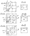
- FIG. 2 shows the exemplary structure of a room 28 of the building 10 according to the invention shown.
- the room 28 has a window arrangement 50 and a door 52 and also has the Transfer openings 26 already mentioned above and the outlet openings 30th
- the transfer openings 26, with the help of air from the hallway 24 also closed door 52 can get into the room 28 are in the area Slider device 54 formed, the structure with reference to Figures 3 and 4 will be explained in more detail.
- a guide 56 is attached, in which a slide 58 is guided.
- the slider 58 can be actuated by an actuator 58a by a person in the room 28 by hand be adjusted.
- the slide 58 has the transfer openings 26 in FIG Wall 28a has corresponding openings 58b that correspond to the transition openings 26 steplessly out of coverage, in any partial coverage or complete coverage can be brought. In figure 3, the openings 26 and 58b are out of overlap.
- the slide device 54 is accordingly in its closed position. A yourself in the room 28 person can thus the supply of fresh air from corridor 24 to room 28 according to your personal needs to adjust.
- the Slider 58 perforations 58c provided in the closed state of the Slide device 54 allows air to pass from the hallway through the transfer openings Allow 26 in room 28.
- the slide device 54 is also provided with check valves 60, which are only one Allow air flow from hallway 24 into room 28 (see FIG. 4), one However, prevent air flow from room 28 into hallway 24.
- the window construction 50 is according to Figure 2 as a sliding box window trained, although of course other window types, too Casement casement windows, simple sliding windows, simple casement windows or the like can be used.
- both the inner box fixed unit 50a and the outer box window unit 50b can be opened as far as possible, so that the person in the room 28 also the ventilation conditions can adapt to their individual needs by means of the window 50.
- the outer box window unit 50b is designed as a baffle, i.e. it points in the area of the window frame or in the glass pane openings 50c themselves. If, for example, the storm is strong inner box window unit 50a is opened, as a result of the storm clearly noticeable air flow through the openings 50c of the outer box window unit 50b so that the person opening the window points to the extreme wind conditions and especially of them is also held to open the outer box window unit 50b.
- the outlet openings 30 provided a minimum air flow rate to the outside environment guarantee.
- the invention Ventilation system with the least architectural requirements, e.g. the double facades often required nowadays in high-rise buildings can also be dispensed with makes and a substantial reduction of the necessary for their operation industrial equipment allowed.
- the invention Ventilation system 12 constructively and in particular also in terms of control technology simply set up.
- the actual regulation of the ventilation conditions is from those staying in rooms 28 of building 10 Made by hand, be it by opening and closing Windows and doors or by operating the slide device 54. Die
- these persons will not take on this regulatory task perceived as disadvantageous, but on the contrary as extremely advantageous, because it the adaptation of the ventilation conditions to their individual Needs.
- the ventilation system only reacts to you given conditions by changing the airflow rate to each Ventilation sectors so that the desired in these sectors Pressure difference ⁇ P between the internal pressure P1 and the external pressure P2 is maintained.
- the control unit 34 of the ventilation system 12 is required only the detection signals from a number of pressure sensors 32.
- Ventilation system 12 also has the advantage that in individual rooms 28 Accidental, negligent or deliberately set extreme ventilation conditions no adverse effect on the operation of the whole Ventilation system 12 can have:
- the ventilation system according to the invention can then, if all doors and windows are intentionally opened at the same time, do not maintain the desired excess pressure in the building 10, even if in this case it works with maximum conveying capacity. Under the conditions mentioned is an adequate supply of fresh air the outside environment through the rooms in the hallways. This The most extreme of all conceivable ventilation situations needs control technology not necessarily to be considered because after Closing at least part of the doors and windows turns the desired overpressure in the building 10 automatically on again.
- 5a, 5b, 6a, 6b, 7a and 7b are schematically different Possibilities shown, the fresh air supplied from the riser to distribute the main ventilation duct to the different rooms.
- the air passes from the main ventilation duct 116A through the transfer opening 122 in a manifold 170 (shown in dashed lines) from which they enters the rooms 128 through transfer openings 126.
- Hallway 124 are two such distribution shafts in the embodiment of Figure 6a 170 and 170 'assigned, each by a separate main ventilation duct are fed. Corridor 124 is therefore two main ventilation channels assigned. A conference room 128 'is created by means of two transfer openings 126 fed.
- the corridor 124 is also supplied from the distribution shafts 170 and 170 ', respectively Outlet openings 172 (see Figure 6b). Otherwise the embodiment corresponds 6a and 6b of the embodiment according to figures 5a and 5b, to the description of which reference is hereby made.
- a high-rise building comes from a low building, such as a family home, usually with a single main ventilation duct out.
- the one running through the ground outside the house Channel section can, for example, of a flexible plastic tube be educated, as it is available in the construction trade or in DIY stores is.
- the length of the channel section laid in the ground is thus too long dimensioned that the intake air at the by the intended air flow and the pipe cross-section predetermined flow rate has enough time to connect to the surrounding canal walls Soil to come into heat exchange contact.
- the pipe length to be laid of course also depends on the geological environmental conditions from. For example, the pipe in the ground is covered by groundwater washed around, a considerably shorter pipe length is sufficient than in the case where the pipe is laid in gravel.
- the suction opening of the main ventilation duct should preferably be on a protected one Place on the side of the building facing away from the sun to ensure that the coolest possible air is drawn in in summer.
- the suction opening should be arranged in one place be at a sufficient distance from motor vehicles Areas, such as roads, garage driveways or the like, is located in order to ensure the suction of clean air.
- the suction opening should be covered with a grille to prevent penetration prevent mice and the like from vermin.
- the ventilation device differs for one low building in its possible execution variants not from that skyscraper explained above. Also with regard to the different execution options the throttle device corresponds to this.
- the suctioned and heated Air simply let out in the basement of the building in the area of the stairwell and spread out from there over the staircase and the hallways the rooms of the building.
- the staircase essentially vertical riser section of the main ventilation duct, while the corridors form the distribution channels.
- This variant is particularly suitable for retrofitting existing ones Building.
- Another expansion step can be that, for example, in Stairwell of the building to plaster a vertical ventilation duct laid, which has a plurality of air outlets. This allows more even ventilation of the building and can also be retrofitted to a building that has already been completed.
- distribution shafts can also be closed be provided in the individual rooms.
- the vertical ventilation duct can also be used integrated into the building structure as part of the main ventilation duct will.
Landscapes
- Engineering & Computer Science (AREA)
- Architecture (AREA)
- Chemical & Material Sciences (AREA)
- Combustion & Propulsion (AREA)
- Mechanical Engineering (AREA)
- General Engineering & Computer Science (AREA)
- Civil Engineering (AREA)
- Structural Engineering (AREA)
- Building Environments (AREA)
- Ventilation (AREA)
Abstract
Description
- Figur 1
- eine grobschematische, geschnittene Seitenansicht eines erfindungsgemäßen Gebäudes;
- Figur 2
- eine schematische Draufsicht eines Raums des erfindungsgemäßen Gebäudes;
- Figur 3
- eine vergrößerte Ansicht des Details A in Figur 2;
- Figur 4
- eine geschnittene Seitenansicht des Details A längs der Linie IV-IV in Figur 3;
- Figuren 5a, 6a und 7a
- schematische Draufsichten auf Teile von Etagen erfindungsgemäßer Gebäude; und
- Figuren 5b, 6b und 7b
- schematische Stirnansichten der Etagen gemäß Figuren 5a, 6a bzw. 7a in Richtung der Pfeile V, VI bzw. VII.
Claims (40)
- Gebäude (10) umfassend:wenigstens einen mit der äußeren Umgebung (U) in Luftübertrittsverbindung stehenden Lüftungshauptkanal (16A, 16B, 16C; 116A; 216A),wenigstens einen Verteilerkanal (24; 170, 170'; 270), welcher zum einen mit dem wenigstens einen Lüftungshauptkanal (16A, 16B, 16C; 116A; 216A), und zum anderen mit Räumen (28; 128, 128'; 228) des Gebäudes in Luftübertrittsverbindung steht, wobei die Räume ihrerseits mit der äußeren Umgebung des Gebäudes in Luftübertrittsverbindung stehen,
gekennzeichnet durch,eine dem wenigstens einen Lüftungshauptkanal (16A, 16B, 16C; 116A; 216A) zugeordnete Belüftungsvorrichtung (36A, 36B, 36C) zum Erzeugen oder/und Aufrechterhalten eines Belüftungsdrucks, dessen Wert (P1) größer ist als der Wert (P2) des in der äußeren Umgebung (U) herrschenden Drucks. - Gebäude nach Anspruch 1,
dadurch gekennzeichnet, daß eine Steuereinheit (34) zur Steuerung des Betriebs der Belüftungsvorrichtung (36A, 36B, 36C) vorgesehen ist. - Gebäude nach Anspruch 1 oder 2,
dadurch gekennzeichnet, daß an der Außenseite des Gebäudes (10) sowie in dem wenigstens einen Verteilerkanal (24) oder/und dem wenigstens einen Lüftungshauptkanal (16A, 16B, 16C) Drucksensoren (32) vorgesehen sind zur Erfassung des am jeweiligen Ort herrschenden Luftdrucks. - Gebäude nach einem der Ansprüche 1 bis 3,
dadurch gekennzeichnet, daß das Gebäude (10) in eine Mehrzahl von Belüftungssektoren (14A, 14B, 14C) unterteilt ist, denen jeweils mindestens ein Lüftungshauptkanal (16A, 16B, 16C) zugeordnet ist - Gebäude nach einem der Ansprüche 1 bis 4,
dadurch gekennzeichnet, daß zwischen dem wenigstens einen Verteilerkanal (24) und einem mit diesem in Luftübertrittsverbindung stehenden Raum (28) oder/und zwischen wenigstens einem der Räume (28) und der äußeren Umgebung (U) eine, vorzugsweise von Hand verstellbare, Vorrichtung (54 bzw. 50) vorgesehen ist zum Verändern des Luftdurchlaßquerschnitts. - Gebäude nach Anspruch 5,
dadurch gekennzeichnet, daß die Vorrichtung (54, 50) zum Verändern des Luftdurchlaßquerschnitts einen endlichen minimalen Luftdurchlaßquerschnitt (58c bzw. 30) aufweist. - Gebäude nach Anspruch 5 oder 6,
dadurch gekennzeichnet, daß die Vorrichtung (54) zum Verändern des Luftdurchlaßquerschnitts eine Rückschlageinrichtung (60) aufweist, welche einen Luftübertritt von der äußeren Umgebung in den Raum bzw. von dem Raum (28) in den zugeordneten Verteilerkanal (24) zumindest erschwert. - Gebäude nach einem der Ansprüche 1 bis 7,
dadurch gekennzeichnet, daß wenigstens ein Verteilerkanal von einem Flur (24) des Gebäudes (10) gebildet ist. - Gebäude nach Anspruch einem der Ansprüche 1 bis 8,
dadurch gekennzeichnet, daß wenigstens ein Verteilerkanal von einem gesonderten Verteilerschacht (170, 170'; 270) gebildet ist. - Gebäude nach einem der Ansprüche 1 bis 9,
dadurch gekennzeichnet, daß das Gebäude (10) eine Einfachfassade aufweist. - Gebäude nach einem der Ansprüche 1 bis 10,
dadurch gekennzeichnet, daß wenigstens einer der Räume (28) ein öffenbares Fenster (50) aufweist. - Gebäude nach einem der Ansprüche 1 bis 11,
dadurch gekennzeichnet, daß wenigstens ein Fenster (50) des Gebäudes (10) als Kastenfenster ausgebildet ist. - Gebäude nach Anspruch 12,
dadurch gekennzeichnet, daß die äußere Fenstereinheit (50b) des Kastenfensters (50) mit einer Prallscheibe ausgebildet ist. - Gebäude nach einem der Ansprüche 1 bis 13,
dadurch gekennzeichnet, daß wenigstens ein Lüftungshauptkanal (16A, 16B, 16C) einen durch das Erdreich (18) bzw. durch ein mit dem Erdreich in Wärmeaustausch stehendes Baukonstruktionsteil verlaufenden Kanalabschnitt (16Ab) aufweist. - Gebäude nach Anspruch 14,
dadurch gekennzeichnet, daß dem wenigstens einen durch das Erdreich bzw. durch das mit dem Erdreich in Wärmeaustausch stehende Baukonstruktionsteil verlaufenden Kanalabschnitt (16Ab) ein Wärmeaustauscher (20) zugeordnet ist. - Gebäude nach einem der Ansprüche 1 bis 15,
dadurch gekennzeichnet, daß dem wenigstens einen Lüftungshauptkanal (16A, 16B, 16C) eine Drosselvorrichtung (38A, 38B, 38C) zugeordnet ist, welche dazu dient, gegebenenfalls dem Aufbau eines zu hohen Belüftungsdrucks entgegenzuwirken. - Gebäude nach Anspruch 16,
dadurch gekennzeichnet, daß die Belüftungsvorrichtung und die Drosselvorrichtung von ein und derselben Vorrichtung gebildet sind, beispielsweise einer Luftschraubenanordnung, die im Druckbetrieb als Gebläse und im Drosselbetrieb als Turbine arbeitet. - Gebäude nach einem der Ansprüche 1 bis 17,
dadurch gekennzeichnet, daß dem wenigstens einen Lüftungshauptkanal (16A, 16B, 16C) eine Heizvorrichtung (40) oder/und eine Kühlvorrichtung (40) zugeordnet ist. - Gebäude nach einem der Ansprüche 1 bis 18,
dadurch gekennzeichnet, daß in den Räumen oder/und dem wenigstens einen Verteilerkanal oder/und dem wenigstens einen Lüftungshauptkanal (16A) Anschlußstellen (44) vorgesehen sind zur Einbringung von durch Fremdwärmequellen (42) erwärmter Luft. - Gebäude nach einem der Ansprüche 1 bis 19,
dadurch gekennzeichnet, daß die Belüftungsvorrichtung (36A, 36B, 36C) in einem Servicebereich (K) des Gebäudes angeordnet ist, beispielsweise im Keller oder einer Service-Etage des Gebäudes. - Gebäude nach einem der Ansprüche 1 bis 20,
dadurch gekennzeichnet, daß die Querschnittsfläche eines Lüftungshauptkanals (16A, 16B, 16C) höchstens 20 m2, vorzugsweise höchstens 10 m2, beträgt. - Gebäude nach einem der Ansprüche 1 bis 21,
dadurch gekennzeichnet, daß das Gebäude (10) mindestens 25 m hoch ist, Vorzugsweise mindestens 50 m. - Gebäude nach einem der Ansprüche 1 bis 22,
dadurch gekennzeichnet, daß der Wert des Druckunterschieds zwischen Gebäudeinnendruck und Umgebungsdruck zwischen 10 Pa und 80 Pa, Vorzugsweise etwa 30 Pa, beträgt. - Gebäude nach einem der Ansprüche 1 bis 23,
dadurch gekennzeichnet, daß der Belüftungsvorrichtung eine Photovoltaik-Vorrichtung (37) zur Erzeugung des zum Betrieb der Belüftungsvorrichtung erforderlichen elektrischen Stroms zugeordnet ist. - Gebäude nach einem der Ansprüche 1 bis 24,
dadurch gekennzeichnet, daß in dem wenigstens einen Lüftungshauptkanal (16A, 16B, 16C) eine Filteranordnung (41) vorgesehen ist, beispielsweise eine Staub- oder/und Pollenfilteranordnung. - Gebäude nach einem der Ansprüche 1 bis 25,
dadurch gekennzeichnet, daß in dem wenigstens einen Lüftungshauptkanal (16A, 16B, 16C) eine Vorrichtung (41) zum Befeuchten oder/und Parfümieren der angesaugten Luft vorgesehen ist. - Gebäude nach einem der Ansprüche 1 bis 26,
dadurch gekennzeichnet, daß in dem wenigstens einen Lüftungshauptkanal (16A, 16B, 16C) ein Temperatursensor zum Erfassen der Temperatur der angesaugten Luft vorgesehen ist. - Gebäude nach Anspruch 16,
dadurch gekennzeichnet, daß in dem wenigstens einen Lüftungshauptkanal (16A, 16B, 16C) eine Drosselklappe (38A, 38B, 38C) angeordnet ist, welche es ermöglicht, die Luftzufuhr in das Gebäude zu drosseln oder/und im wesentlichen vollständig zu unterbinden. - Belüftungsvorrichtung für ein Gebäude (10) nach einem der Ansprüche 1 bis 28, umfassend:wenigstens einen Lüftungshauptkanal (16A, 16B, 16C) mit einem durch das Erdreich (18) bzw. durch ein mit dem Erdreich in Wärmeaustausch stehendes Baukonstruktionsteil verlaufenden Kanalabschnitt (16Ab),wenigstens einen in dem Lüftungshauptkanal (16A, 16B, 16C) angeordneten Ventilator (36A, 36B, 36C), undeine Steuereinheit (34) zur Steuerung des Betriebs des Ventilators (36A, 36B, 36C).
- Belüftungsvorrichtung nach Anspruch 29,
dadurch gekennzeichnet, daß dem wenigstens einen durch das Erdreich bzw. durch das mit dem Erdreich in Wärmeaustausch stehende Baukonstruktionsteil verlaufenden Kanalabschnitt (16Ab) ein Wärmeaustauscher (20) zugeordnet ist. - Belüftungsvorrichtung nach Anspruch 29 oder 30,
dadurch gekennzeichnet, daß dem wenigstens einen Lüftungshauptkanal (16A, 16B, 16C) eine Heizvorrichtung (40) oder/und eine Kühlvorrichtung (40) zugeordnet ist. - Belüftungsvorrichtung nach einem der Ansprüche 29 bis 31,
dadurch gekennzeichnet, daß ihr eine Photovoltaik-Vorrichtung (37) zur Erzeugung des zum Betrieb des wenigstens einen Ventilators (36A, 36B, 36C) erforderlichen elektrischen Stroms zugeordnet ist. - Belüftungsvorrichtung nach einem der Ansprüche 29 bis 32,
dadurch gekennzeichnet, daß in dem wenigstens einen Lüftungshauptkanal (16A, 16B, 16C) eine Filteranordnung (41) vorgesehen ist, beispielsweise eine Staub- oder/und Pollenfilteranordnung. - Belüftungsvorrichtung nach einem der Ansprüche 29 bis 33,
dadurch gekennzeichnet, daß in dem wenigstens einen Lüftungshauptkanal (16A, 16B, 16C) eine Vorrichtung (41) zum Befeuchten oder/und Parfümieren der angesaugten Luft vorgesehen ist. - Belüftungsvorrichtung nach einem der Ansprüche 29 bis 34,
dadurch gekennzeichnet, daß dem wenigstens einen Lüftungshauptkanal (16A, 16B, 16C) eine Drosselvorrichtung (38A, 38B, 38C) zugeordnet ist, welche dazu dient, gegebenenfalls dem Aufbau eines zu hohen Belüftungsdrucks entgegenzuwirken. - Belüftungsvorrichtung nach Anspruch 35,
dadurch gekennzeichnet, daß der Ventilator und die Drosselvorrichtung von ein und derselben Vorrichtung gebildet sind, beispielsweise einer Luftschraubenanordnung, die im Druckbetrieb als Gebläse und im Drosselbetrieb als Turbine arbeitet. - Belüftungsvorrichtung nach Anspruch 35,
dadurch gekennzeichnet, daß in dem wenigstens einen Lüftungshauptkanal (16A, 16B, 16C) eine Drosselklappe (38A, 38B, 38C) angeordnet ist, welche es ermöglicht, die Luftzufuhr in das Gebäude zu drosseln oder/und im wesentlichen vollständig zu unterbinden. - Belüftungsvorrichtung nach einem der Ansprüche 29 bis 37,
dadurch gekennzeichnet, daß zur Anordnung an der Außenseite des Gebäudes (10) sowie in dem wenigstens einen Verteilerkanal (24) oder/und dem wenigstens einen Lüftungshauptkanal (16A, 16B, 16C) bestimmte Drucksensoren (32) vorgesehen sind zur Erfassung des am jeweiligen Ort herrschenden Luftdrucks. - Bausatz für eine Belüftungsvorrichtung nach einem der Ansprüche nach einem der Ansprüche 29 bis 38, umfassend:wenigstens einen Kanalabschnitt (16Ab), der dazu bestimmt ist, im Erdreich (18) bzw. in einem mit dem Erdreich in Wärmeaustausch stehenden Baukonstruktionsteil verlegt zu werden,wenigstens einen Ventilator (36A, 36B, 36C), undeine Steuereinheit (34) zur Steuerung des Betriebs des Ventilators (36A, 36B, 36C).
- Bausatz nach Anspruch 39,
dadurch gekennzeichnet, daß er ferner wenigstens eine der folgenden Vorrichtungen aufweist:einen Wärmeaustauscher (20),eine Heizvorrichtung (40) oder/und eine Kühlvorrichtung (40),eine Photovoltaik-Vorrichtung (37),eine Filteranordnung (41),eine Vorrichtung (41) zum Befeuchten oder/und Parfümieren der angesaugten Luft,eine Drosselvorrichtung (38A, 38B, 38C), beispielsweise eine Drosselklappe (38A, 38B, 38C),wenigstens einen Luftdrucksensor (32),wenigstens einen Temperatursensor.
Applications Claiming Priority (9)
| Application Number | Priority Date | Filing Date | Title |
|---|---|---|---|
| DE1997119367 DE19719367A1 (de) | 1997-05-07 | 1997-05-07 | Gebäude |
| DE19719367 | 1997-05-07 | ||
| DE29708247U | 1997-05-07 | ||
| DE29708247U DE29708247U1 (de) | 1997-05-07 | 1997-05-07 | Gebäude |
| JP15359997 | 1997-06-11 | ||
| JP153599/97 | 1997-06-11 | ||
| JP15359997A JPH10311577A (ja) | 1997-05-07 | 1997-06-11 | ビルディング |
| US88476397A | 1997-06-30 | 1997-06-30 | |
| US884763 | 1997-06-30 |
Publications (3)
| Publication Number | Publication Date |
|---|---|
| EP0877209A2 true EP0877209A2 (de) | 1998-11-11 |
| EP0877209A3 EP0877209A3 (de) | 2001-09-19 |
| EP0877209B1 EP0877209B1 (de) | 2005-01-05 |
Family
ID=27438594
Family Applications (1)
| Application Number | Title | Priority Date | Filing Date |
|---|---|---|---|
| EP98108272A Expired - Lifetime EP0877209B1 (de) | 1997-05-07 | 1998-05-06 | Belüftungsvorrichtung für ein Gebäude |
Country Status (4)
| Country | Link |
|---|---|
| EP (1) | EP0877209B1 (de) |
| AT (1) | ATE286587T1 (de) |
| ES (1) | ES2236844T3 (de) |
| PT (1) | PT877209E (de) |
Cited By (2)
| Publication number | Priority date | Publication date | Assignee | Title |
|---|---|---|---|---|
| KR20030003997A (ko) * | 2001-07-04 | 2003-01-14 | 이만수 | 고층 실내공기 정압기(aspl) |
| ES2265200A1 (es) * | 2003-07-11 | 2007-02-01 | Victor Julian Calero Gomez | Sistema de ventilacion y salida de gases conducida. |
Families Citing this family (1)
| Publication number | Priority date | Publication date | Assignee | Title |
|---|---|---|---|---|
| DE20318408U1 (de) * | 2003-11-28 | 2004-03-11 | I.F.I. Institut für Industrieaerodynamik GmbH | Vorrichtung zur gezielten Einstellung einer horizontalen Druckverteilung in Hochhäusern |
Citations (4)
| Publication number | Priority date | Publication date | Assignee | Title |
|---|---|---|---|---|
| US2282210A (en) * | 1937-01-22 | 1942-05-05 | Honeywell Regulator Co | Air conditioning system |
| US4323113A (en) * | 1980-10-31 | 1982-04-06 | Troyer Leroy S | Underground air tempering system |
| US4392417A (en) * | 1979-04-30 | 1983-07-12 | Mcquay-Perfex Inc. | Variable dead band pressure control system |
| US5554071A (en) * | 1991-03-20 | 1996-09-10 | Abb Flakt Oy | Air-change system for a multi-storey building |
-
1998
- 1998-05-06 AT AT98108272T patent/ATE286587T1/de active
- 1998-05-06 PT PT98108272T patent/PT877209E/pt unknown
- 1998-05-06 EP EP98108272A patent/EP0877209B1/de not_active Expired - Lifetime
- 1998-05-06 ES ES98108272T patent/ES2236844T3/es not_active Expired - Lifetime
Patent Citations (4)
| Publication number | Priority date | Publication date | Assignee | Title |
|---|---|---|---|---|
| US2282210A (en) * | 1937-01-22 | 1942-05-05 | Honeywell Regulator Co | Air conditioning system |
| US4392417A (en) * | 1979-04-30 | 1983-07-12 | Mcquay-Perfex Inc. | Variable dead band pressure control system |
| US4323113A (en) * | 1980-10-31 | 1982-04-06 | Troyer Leroy S | Underground air tempering system |
| US5554071A (en) * | 1991-03-20 | 1996-09-10 | Abb Flakt Oy | Air-change system for a multi-storey building |
Cited By (2)
| Publication number | Priority date | Publication date | Assignee | Title |
|---|---|---|---|---|
| KR20030003997A (ko) * | 2001-07-04 | 2003-01-14 | 이만수 | 고층 실내공기 정압기(aspl) |
| ES2265200A1 (es) * | 2003-07-11 | 2007-02-01 | Victor Julian Calero Gomez | Sistema de ventilacion y salida de gases conducida. |
Also Published As
| Publication number | Publication date |
|---|---|
| PT877209E (pt) | 2005-04-29 |
| EP0877209A3 (de) | 2001-09-19 |
| ATE286587T1 (de) | 2005-01-15 |
| ES2236844T3 (es) | 2005-07-16 |
| EP0877209B1 (de) | 2005-01-05 |
Similar Documents
| Publication | Publication Date | Title |
|---|---|---|
| EP0044560B1 (de) | Belüftungsanlage für im Zwangsumlauf belüftete Räume | |
| EP1062463B1 (de) | Klimatisierungsverfahren von gebäuden sowie klimatisiertes gebäude | |
| EP0467876B1 (de) | Hochhaus | |
| EP2450520B1 (de) | Kontrolliertes Lüftungssytem für ein Gebäude mittels eines Türelements | |
| DE202004008792U1 (de) | Zentrales Lüftungssystem zur Lüftung eines Wohngebäudes | |
| EP0555658B1 (de) | Klimatisierungsanlage für ein Gebäude | |
| EP2394103B1 (de) | Bauwerk und verfahren zum temperieren und belüften des bauwerks | |
| EP0164111A2 (de) | Schall-und Wärmeisolierendes Verbundfenster mit Schalldämmlüftung | |
| DE19809974A1 (de) | Klimatisierung von Gebäuden | |
| DE102008063555A1 (de) | Raumlufttechnisches Gerät sowie Verfahren zum Betreiben des raumlufttechnischen Geräts | |
| EP0877209B1 (de) | Belüftungsvorrichtung für ein Gebäude | |
| EP3220068B1 (de) | Belüftungssystem zur erzeugung eines luftstroms in einem gebäude | |
| EP0951630B1 (de) | Raumbelüftungsverfahren und vorrichtung zur durchführung des verfahrens | |
| DE19719367A1 (de) | Gebäude | |
| EP1507046B1 (de) | Bausatz für ein Energiesparhaus | |
| DE19639128C2 (de) | Lüftungswärmetauscher | |
| AT500559B1 (de) | Raumlufttechnische einrichtung | |
| DE3728698A1 (de) | Klimaanlage | |
| EP1330579A1 (de) | Niedrigenergiegebäude | |
| DE10253264C5 (de) | Dezentrale lufttechnische Einrichtung sowie Verfahren zum dezentralen Heizen oder Kühlen eines Raumes | |
| DE202008016732U1 (de) | Raumlufttechnisches Gerät | |
| EP0142596A1 (de) | Wärmedämmendes Fenster | |
| DE2922441A1 (de) | Hochdruckklimageraet fuer energiesparbetrieb | |
| EP0358121A2 (de) | Luftführendes Fenster | |
| EP4357689A1 (de) | System und verfahren zur rauchfreihaltung einer vertikalen zugangsverbindung eines mehrgeschossigen gebäudes |
Legal Events
| Date | Code | Title | Description |
|---|---|---|---|
| PUAI | Public reference made under article 153(3) epc to a published international application that has entered the european phase |
Free format text: ORIGINAL CODE: 0009012 |
|
| AK | Designated contracting states |
Kind code of ref document: A2 Designated state(s): AT BE CH CY DE DK ES FI FR GB GR IE IT LI LU MC NL PT SE Kind code of ref document: A2 Designated state(s): AT DE ES FR GR IT PT |
|
| AX | Request for extension of the european patent |
Free format text: AL;LT;LV;MK;RO;SI |
|
| PUAL | Search report despatched |
Free format text: ORIGINAL CODE: 0009013 |
|
| AK | Designated contracting states |
Kind code of ref document: A3 Designated state(s): AT BE CH CY DE DK ES FI FR GB GR IE IT LI LU MC NL PT SE |
|
| AX | Request for extension of the european patent |
Free format text: AL;LT;LV;MK;RO;SI |
|
| RIC1 | Information provided on ipc code assigned before grant |
Free format text: 7F 24F 11/00 A, 7F 24F 7/06 B, 7F 24F 3/044 B |
|
| 17P | Request for examination filed |
Effective date: 20011221 |
|
| AKX | Designation fees paid |
Free format text: AT DE ES FR GR IT PT |
|
| 17Q | First examination report despatched |
Effective date: 20031121 |
|
| GRAP | Despatch of communication of intention to grant a patent |
Free format text: ORIGINAL CODE: EPIDOSNIGR1 |
|
| GRAS | Grant fee paid |
Free format text: ORIGINAL CODE: EPIDOSNIGR3 |
|
| GRAA | (expected) grant |
Free format text: ORIGINAL CODE: 0009210 |
|
| AK | Designated contracting states |
Kind code of ref document: B1 Designated state(s): AT DE ES FR GR IT PT |
|
| REF | Corresponds to: |
Ref document number: 59812461 Country of ref document: DE Date of ref document: 20050210 Kind code of ref document: P |
|
| REG | Reference to a national code |
Ref country code: GR Ref legal event code: EP Ref document number: 20050400136 Country of ref document: GR |
|
| REG | Reference to a national code |
Ref country code: PT Ref legal event code: SC4A Free format text: AVAILABILITY OF NATIONAL TRANSLATION Effective date: 20050304 |
|
| REG | Reference to a national code |
Ref country code: ES Ref legal event code: FG2A Ref document number: 2236844 Country of ref document: ES Kind code of ref document: T3 |
|
| PLBE | No opposition filed within time limit |
Free format text: ORIGINAL CODE: 0009261 |
|
| STAA | Information on the status of an ep patent application or granted ep patent |
Free format text: STATUS: NO OPPOSITION FILED WITHIN TIME LIMIT |
|
| 26N | No opposition filed |
Effective date: 20051006 |
|
| ET | Fr: translation filed | ||
| PG25 | Lapsed in a contracting state [announced via postgrant information from national office to epo] |
Ref country code: PT Free format text: LAPSE BECAUSE OF NON-PAYMENT OF DUE FEES Effective date: 20060208 |
|
| PG25 | Lapsed in a contracting state [announced via postgrant information from national office to epo] |
Ref country code: PT Free format text: LAPSE BECAUSE OF NON-PAYMENT OF DUE FEES Effective date: 20050506 |
|
| PGFP | Annual fee paid to national office [announced via postgrant information from national office to epo] |
Ref country code: GR Payment date: 20090428 Year of fee payment: 12 |
|
| PG25 | Lapsed in a contracting state [announced via postgrant information from national office to epo] |
Ref country code: GR Free format text: LAPSE BECAUSE OF NON-PAYMENT OF DUE FEES Effective date: 20101202 |
|
| PGFP | Annual fee paid to national office [announced via postgrant information from national office to epo] |
Ref country code: FR Payment date: 20110614 Year of fee payment: 14 Ref country code: ES Payment date: 20110624 Year of fee payment: 14 |
|
| PGFP | Annual fee paid to national office [announced via postgrant information from national office to epo] |
Ref country code: AT Payment date: 20110531 Year of fee payment: 14 |
|
| PGFP | Annual fee paid to national office [announced via postgrant information from national office to epo] |
Ref country code: DE Payment date: 20110531 Year of fee payment: 14 Ref country code: IT Payment date: 20110531 Year of fee payment: 14 |
|
| REG | Reference to a national code |
Ref country code: AT Ref legal event code: MM01 Ref document number: 286587 Country of ref document: AT Kind code of ref document: T Effective date: 20120506 |
|
| PG25 | Lapsed in a contracting state [announced via postgrant information from national office to epo] |
Ref country code: AT Free format text: LAPSE BECAUSE OF NON-PAYMENT OF DUE FEES Effective date: 20120506 |
|
| PG25 | Lapsed in a contracting state [announced via postgrant information from national office to epo] |
Ref country code: IT Free format text: LAPSE BECAUSE OF NON-PAYMENT OF DUE FEES Effective date: 20120506 |
|
| REG | Reference to a national code |
Ref country code: FR Ref legal event code: ST Effective date: 20130131 |
|
| REG | Reference to a national code |
Ref country code: DE Ref legal event code: R119 Ref document number: 59812461 Country of ref document: DE Effective date: 20121201 |
|
| PG25 | Lapsed in a contracting state [announced via postgrant information from national office to epo] |
Ref country code: FR Free format text: LAPSE BECAUSE OF NON-PAYMENT OF DUE FEES Effective date: 20120531 |
|
| PG25 | Lapsed in a contracting state [announced via postgrant information from national office to epo] |
Ref country code: DE Free format text: LAPSE BECAUSE OF NON-PAYMENT OF DUE FEES Effective date: 20121201 |
|
| REG | Reference to a national code |
Ref country code: ES Ref legal event code: FD2A Effective date: 20130821 |
|
| PG25 | Lapsed in a contracting state [announced via postgrant information from national office to epo] |
Ref country code: ES Free format text: LAPSE BECAUSE OF NON-PAYMENT OF DUE FEES Effective date: 20120507 |