EP0877178B1 - Chaine utilisant des douilles conformés munies de dents - Google Patents
Chaine utilisant des douilles conformés munies de dents Download PDFInfo
- Publication number
- EP0877178B1 EP0877178B1 EP98302805A EP98302805A EP0877178B1 EP 0877178 B1 EP0877178 B1 EP 0877178B1 EP 98302805 A EP98302805 A EP 98302805A EP 98302805 A EP98302805 A EP 98302805A EP 0877178 B1 EP0877178 B1 EP 0877178B1
- Authority
- EP
- European Patent Office
- Prior art keywords
- chain
- pair
- bushings
- links
- link plates
- Prior art date
- Legal status (The legal status is an assumption and is not a legal conclusion. Google has not performed a legal analysis and makes no representation as to the accuracy of the status listed.)
- Expired - Lifetime
Links
Images


Classifications
-
- F—MECHANICAL ENGINEERING; LIGHTING; HEATING; WEAPONS; BLASTING
- F16—ENGINEERING ELEMENTS AND UNITS; GENERAL MEASURES FOR PRODUCING AND MAINTAINING EFFECTIVE FUNCTIONING OF MACHINES OR INSTALLATIONS; THERMAL INSULATION IN GENERAL
- F16G—BELTS, CABLES, OR ROPES, PREDOMINANTLY USED FOR DRIVING PURPOSES; CHAINS; FITTINGS PREDOMINANTLY USED THEREFOR
- F16G13/00—Chains
- F16G13/02—Driving-chains
- F16G13/04—Toothed chains
-
- F—MECHANICAL ENGINEERING; LIGHTING; HEATING; WEAPONS; BLASTING
- F16—ENGINEERING ELEMENTS AND UNITS; GENERAL MEASURES FOR PRODUCING AND MAINTAINING EFFECTIVE FUNCTIONING OF MACHINES OR INSTALLATIONS; THERMAL INSULATION IN GENERAL
- F16G—BELTS, CABLES, OR ROPES, PREDOMINANTLY USED FOR DRIVING PURPOSES; CHAINS; FITTINGS PREDOMINANTLY USED THEREFOR
- F16G13/00—Chains
- F16G13/02—Driving-chains
- F16G13/06—Driving-chains with links connected by parallel driving-pins with or without rollers so called open links
Definitions
- the present invention relates generally to power transmission chains.
- the invention has particular application to power transmission chains of the silent chain or roller chain variety, which are used in engine timing applications as well as in industrial applications.
- Power transmission chains are widely used in the automotive industry. Such chains are used for engine timing drives as well as for the transfer of power from the engine to the transmission or for the transfer of power in a transfer case. Power transmission chains are also widely used in industrial applications.
- silent chain One type of chain is known as a "silent chain.”
- a typical silent chain consists of interleaved sets of inverted tooth links.
- a set or rank of links is assembled from several links positioned alongside of or adjacent to each other.
- the links are connected by pivot means, which are typically round pins received in a pair of apertures.
- pivot means typically round pins received in a pair of apertures.
- a conventional silent chain typically includes both guide links and inverted tooth links.
- the guide links are positioned on the outside edges of alternate sets of links.
- the guide links typically act to position the chain laterally on the sprocket.
- Guide links typically do not mesh with the sprocket.
- the inverted tooth links -- or "sprocket-engaging" links -- provide the transfer of power between the chain and sprocket.
- Each inverted tooth link typically includes a pair of apertures and a pair of depending toes. Each toe is defined by an inside flank and an outside flank. The inside flanks are joined at a crotch.
- the inverted tooth links are typically designed so that the links contact the sprocket teeth to transfer power between the chain assembly and the sprocket.
- the inverted tooth links or driving links contact the sprocket teeth along their inside flanks or their outside flanks or combinations of both flanks.
- the contacts between the links and the sprocket teeth can be of the type which provide a power transfer, or can be of the nature of an incidental contact, or can include root contact or side contact.
- a conventional silent chain drive is comprised of an endless silent chain wrapped about at least two sprockets supported by shafts. Rotation of a driving sprocket causes power transmission through the chain and consequent movement of a driven sprocket.
- the driving sprocket is mounted on the engine crankshaft and the driven sprocket is mounted on the camshaft. The rotation of a camshaft is thus controlled by and dependent on the rotation of the crankshaft through the chain.
- a chain for an engine timing drive application is shown in U.S. Patent No. 4,758,210.
- roller chain Another type of chain is known as a "roller chain.”
- a typical roller chain consists of alternate inner links and outer links.
- the inner links which are also known as “bushing” links, consist of spaced link plates with bushings tightly received in apertures at each end of the link plates.
- the outer links which are also known as “guide” links, consist of spaced link plates with pins tightly received in apertures at each end of the link plates.
- the bushings freely rotate about the pins to pivotally connect the outer links to the inner links in alternate arrangement.
- Rollers may be provided about the bushings, and when the roller chain is wrapped about a sprocket, the teeth of the sprocket are received between the laterally spaced link plates and the longitudinally spaced rollers. Examples of roller chains are found in U.S. Patent Nos. 4,186,617 and 5,226,856.
- a conventional roller chain drive is comprised of an endless roller chain wrapped about at least two sprockets supported by shafts. Rotation of a driving sprocket causes power transmission through the chain and consequent movement of a driven sprocket.
- the driving sprocket is mounted on the engine crankshaft and the driven sprocket is mounted on the camshaft. The rotation of a camshaft is thus controlled by and dependent on the rotation of the crankshaft through the chain.
- Various types of engine timing systems and configurations, which are suitable for roller and inverted tooth chain assemblies, are shown in U.S. Patent No. 5,427,580.
- Noise is associated with chain drives, and is generated by a variety of sources.
- noise can be generated from the impact of the collision between the chain and the sprocket at the onset of meshing.
- the loudness of the impact sound is affected by, among other things, the impact velocity between the chain and the sprocket and the impact of the steel rollers or bushings against the steel or powered metal sprockets.
- Roller chains can be used in automotive applications, but are usually limited to applications where noise generation is not of primary concern. Roller chains are characterized by components with increased resistance to wear.
- a silent chain is superior to a roller chain with regards to noise and vibration characteristics.
- a typical silent chain suffers from inherent design weaknesses arising from mass, cost, pin and link wear, guide wear and efficiency, and sprocket wear.
- Silent chains typically are of higher mass than roller chains, and are therefore typically more costly to produce.
- the pins and links contact in an interrupted fashion, providing a non-uniform bearing surface susceptible to high wear in abrasive environments. Similar to the pin and link bearing surface, the link surfaces engaging the sprocket are also interrupted. This creates high contact pressures on engagement and results in spalling type wear.
- the present invention provides a new roller chain assembly having the engagement properties of a silent chain as a result of a bushing with a silent chain link profile.
- the hybrid chain design of the present invention incorporates the superior noise and vibration characteristics of a typical silent chain, as well as advantages of a typical roller chain, including high stiffness and low mass.
- the present invention provides a chain assembly, comprising: a plurality of interleaved outer links and inner links, said outer links each being formed by a pair of outer link plates, said inner links each being formed by a pair of inner link plates; a pair of pin members fixedly mounted to each said pair of outer link plates; and a pair of bushings of a first type fixedly mounted to each said pair of inner link plates, said first type bushings being mounted and freely rotatable about said pin members.
- a chain assembly is known from US-A-5 226 856.
- the invention is characterised in that a bushing of a second type is mounted about each said pair of first type bushings, said second type bushing including an upper edge and a pair of spaced toes extending downwardly from said upper edge, defining an aperture and forming a crotch between said pair of spaced toes, said crotch dividing said aperture into two separate portions, each of said first type bushings being seated in one of said aperture portions.
- the bushings of the second type are bushings that each include a pair of depending teeth or toes, which engage the sprocket teeth to provide power transmission.
- the present invention also resides in a chain and sprocket assembly including a chain assembly according to the invention and a plurality of sprockets each having a plurality of sprocket teeth that are constructed to mesh with the depending toes of the formed bushing of the chain assembly.
- the present invention provides the high strength to mass ratio and the high stiffness to mass ratio associated with roller chains.
- the present invention is also characterised by its low mass, which provides improved suitability for high speed applications. Further, the present invention requires fewer components that a typical roller chain which, coupled with its low mass, results in lower cost.
- the nature by which the chain engages the sprocket in the present invention results in the low noise and vibration usually associated with silent chains. Because the present invention includes a continuous engagement surface rather than several surfaces of varying dimensions, it is subject to lower contact pressure with the sprocket surface than typical silent chains. The resulting impact vectors also decrease the likelihood of impact failures associated with roller chains.
- the present invention also provides more space on the backside of the chain for lubricating oil to penetrate the chain and provide an oil film for guide surface wear.
- the ability of lubricating oil to more easily penetrate the chain can result in improved efficiency over typical silent chains with tightly interlaced link plates.
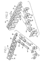
- FIG. 1 illustrates a portion of a roller chain of the prior art generally at 20 .
- the chain 20 is constructed by a series of links, pins, bushing and rollers.
- the chain includes a series of interleaved outer links 22 and inner links 24 .
- the outer links are formed by a pair of outer link plates 26 and 27 .
- the inner links are formed by a pair of inner link plates 28 and 29 .
- the outer link plates 26 and 27 are fixed to a pair of pin members 30 and 32 .
- the pin members are spaced apart and fitted through apertures 31 in the outer link plates 26 and 27 .
- the inner links plates 28 and 29 are fixed to a pair of bushings 34 and 36 .
- the bushings 34 and 36 are generally cylindrical in shape.
- the bushings 34 and 36 are spaced apart and fitted through apertures 38 in the inner link plates 28 and 29 .
- the bushings 34 and 36 are typically secured in the inner link plates 28 and 29 by a press fit, or by welding, caulking, or any other means known in the art.
- the bushings 34 and 36 are mounted about the pin members 30 and 32 and are freely rotatable about the pin members 30 and 32 . Rotation of the bushings 34 and 36 about the pin members 30 and 32 allows pivoting of the outer links 22 with respect to the inner links 24 .
- rollers 39 are mounted about the bushings 34 and 36 and are freely rotatable about the bushings 34 and 36 .
- the rollers 39 are generally cylindrical in shape and contact the sprocket teeth of the sprocket assembly (not shown).
- the chain of FIG. 1 is constructed by inserting the pin member within the bushing and the bushing within the roller.
- the bushings are secured to a pair of inner link plates and the pins are then secured to a pair of outer link plates.
- the inner links and outer links are alternated in series to form an endless chain.
- the length of the chain and exact number of links is determined by, among other things, the application and center distance between the sprockets.
- FIG. 2 illustrates a silent chain of the prior art generally at 40 .
- the chain 40 is constructed by a series of links and pivot members.
- the chain includes a series of interleaved guide link rows 42 and inner link rows 44 .
- the guide link rows 42 are formed by a pair of guide link plates 46 and 47 .
- the inner link rows 44 are formed by a series of inner link plates 48.
- the inner link rows 44 are each interlaced with one set of inner link plates 48 in the guide link row 42 and another set of inner link plates 48 in the non-guide link row.
- the guide link plates 46 and 47 are press fit on a pair of pivot members 50 .
- the pivot members 50 are typically secured in the guide link plates 46 and 47 by a press fit within apertures 54 of the guide link plates 46 and 47 .
- the pivot members 50 are rotatably received in apertures 56 of the inner link plates 48 .
- the inner link plates 48 are each defined by a pair of spaced toes 58 and 59 . The spaced toes 58 and 59 contact and engage the sprocket teeth of the sprocket assembly (not shown).
- the chain of FIG. 2 is constructed by inserting the pivot members within the apertures of the inner link plates, and securing the pivot members within the apertures of the guide link plates.
- the guide link plates maintain the lateral alignment of the chain on the sprocket, while the inner link plates engage the sprocket teeth.
- the guide link rows are interleaved with the inner link rows and the inner link rows are interlaced with each other to form an endless chain.
- the length of the chain and the exact number of link rows is determined by, among other things, the application and center distance between the sprockets.
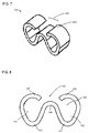
- FIG. 3 illustrates generally at 60 a chain assembly having the formed bushing feature of the present invention.
- the chain 60 is constructed by a series of links, pins, and bushings.
- the complete chain and sprocket assembly (not shown) includes an endlessly connected chain 60 wrapped about at least a pair of sprocket assemblies.
- the sprocket assemblies are mounted on shafts, such as an engine crankshaft or engine camshaft.
- the sprocket assemblies may be of unequal diameters and may have an unequal number of teeth of various shapes.
- the chain and sprocket assembly can also include an idler sprocket.
- the chain 60 includes a series of interleaved outer links 62 and inner links 64.
- the outer links 62 are formed by a pair of outer link plates 66 and 67.
- the inner links 64 are formed by a pair of inner link plates 68 and 69 .
- the outer link plates 66 and 67 are fixed to a pair of pin members 70 and 72 by a press fit or by welding, caulking, or any other means known in the art. Pin members 70 and 72 are spaced apart and fitted through apertures 78 in the outer link plates 66 and 67 .
- the inner link plates 68 and 69 are fixed to a pair of rounded bushings 74 and 76 by a press fit or by welding, caulking, or any other means known in the art.
- the rounded bushings 74 and 76 are spaced apart and fitted through apertures 79 in the inner link plates 68 and 69 .
- the rounded bushings 74 and 76 are mounted about the pin members 70 and 72 and are freely rotatable about the pin members 70 and 72 . Thus, a rotation of the rounded bushings 74 and 76 about the pin members 70 and 72 allows pivoting of the outer links 62 with respect to the inner links 64 .
- the formed bushings 80 are mounted about the rounded bushings 74 and 76 and may be freely rotatable about the rounded bushings 74 and 76.
- the rounded bushings 74 and 76 may also be tightly fit with the formed bushings 80 .
- the formed bushings 80 each include a continuous upper edge 84 and a pair of inverted teeth or depending toes 86 and 87 .
- the depending toes 86 and 87 extend downward from the upper edge 84 of the formed bushing 80.
- the depending toes 86 and 87 and upper edge 84 define an aperture 82 in which the rounded bushings 74 and 76 are mounted.
- the depending toes 86 and 87 define a crotch 88 between them.
- the crotch 88 divides the aperture 82 into at least two portions 90 and 92 .
- the rounded bushings 74 and 76 are each rotatably mounted in one of the two portions 90 and 92 .
- FIG. 4 also illustrates the depending toes 86 and 87 each defined by an inside flank 94 and an outside flank 96 .
- the inside flanks 94 are slightly curved and the outside flanks 96 are generally curved for the major parts of their extents.
- the inside flanks 94 and outside flanks 96 may be curved or straight, or in any combination or proportion thereof.
- FIG. 7 illustrates another embodiment of the present invention, in which the formed bushings 120 each include an upper edge 124 with a split surface, separated by a gap 125 .
- the formed bushings 120 include a pair of inverted teeth or depending toes 126 and 127 .
- the depending toes 126 and 127 extend downward from the split-surfaced upper edge 124 of the formed bushing 120 .
- the depending toes 126 and 127 define a crotch 128 between them, and the crotch 128 divides the aperture 122 into at least two portions 130 and 132 .
- the formed bushings 120 are aligned with and secured to an inner link plate 68 .
- the rounded bushings 114 and 116 are each rotatably mounted in one of the two portions 130 and 132 .
- the rounded bushings 114 and 116 may also be tightly fit with the formed bushings 120 .
- the chain assembly 60 is constructed by securing the rounded bushings 74 and 76 to a pair of inner link plates 68 and 69 .
- the pin members 70 and 72 are inserted within the rounded bushings 74 and 76 , and secured to a pair of outer link plates 66 and 67 .
- the rounded bushings 74 and 76 are rotatably mounted and received in the aperture 82 of the formed bushing 80 .
- the outer links 62 and inner links 64 are alternated in series to form an endless chain. The length of the chain and exact number of links is determined by, among other things, the application and center distance between the sprocket assemblies.
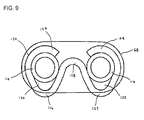
- FIG. 6 illustrates a silent chain and sprocket assembly 100 , comprising a sprocket assembly 102 and the chain 60 with the formed bushing feature of the present invention.
- the formed bushings 80 of the chain 60 contact and engage the sprocket teeth 104 of the sprocket assembly 102.
- the formed bushings 80 include a pair of depending toes 86 and 87 , which define a crotch 88.
- the crotch 88 of the formed bushings 80 receives the sprocket teeth 104 of the sprocket assembly 102 .
Landscapes
- Engineering & Computer Science (AREA)
- General Engineering & Computer Science (AREA)
- Mechanical Engineering (AREA)
- Devices For Conveying Motion By Means Of Endless Flexible Members (AREA)
- Gears, Cams (AREA)
Claims (3)
- Ensemble de chaíne, comprenant :caractérisé en ce queune pluralité de chaínons externes (62) et de chaínons internes (64) intercalés, lesdits chaínons externes étant chacun formé par une paire de maillons externe (66, 67), lesdits chaínons internes étant chacun formés par une paire de maillons interne (68, 69) ;une paire d'éléments de cheville (70, 72) montée de manière fixe à chaque dite paire de maillons externes ; etune paire de douilles (74, 76 ; 114, 116) d'un premier type montée de manière fixe à chaque dite paire de maillons de lien internes, lesdites douilles du premier type étant montées et librement rotatives autour desdits éléments de cheville ;
une douille (80 ; 120) d'un second type est montée autour de chaque dite paire des douilles (74, 76 ; 114, 116) du premier type, ladite douille (80 ; 120) du second type comprenant un bord supérieur (84 ; 124) et une paire d'ergots espacés (86, 87 ; 126, 127) s'étendant vers le bas à partir dudit bord supérieur, définissant une ouverture (82 ; 122) et formant une béquille (88 ; 128) entre ladite paire d' ergots espacés, ladite béquille divisant ladite ouverture (82 ; 122) en deux parties séparées (90, 92 ; 130, 132), chacune desdites douilles (74, 76) du premier type reposant dans l'une desdites parties d'ouverture (90, 92 ; 130, 132). - Ensemble de chaíne selon la revendication 1, dans lequel :ledit bord supérieur (124) de chaque dite douille (120) de second type inclut deux surfaces supérieures, lesdites surfaces supérieures étant espacées l'une de l'autre, chaque surface supérieure comportant un ergot (126, 127) s'étendant vers le bas.
- Ensemble de chaíne et de roues à chaíne, comprenant :un ensemble de chaíne selon la revendication 1 ou 2 ; etune pluralité de roues à chaíne (162), lesdites roues à chaíne comportant chacun une pluralité de dents (104), lesdites dents de roue à chaíne mettant en contact lesdits ergots (86, 87 ; 126, 127) de douille pour assurer une transmission de puissance entre eux.
Applications Claiming Priority (2)
| Application Number | Priority Date | Filing Date | Title |
|---|---|---|---|
| US853835 | 1997-05-09 | ||
| US08/853,835 US5800301A (en) | 1997-05-09 | 1997-05-09 | Chain assembly using formed bushings with inverted teeth |
Publications (2)
| Publication Number | Publication Date |
|---|---|
| EP0877178A1 EP0877178A1 (fr) | 1998-11-11 |
| EP0877178B1 true EP0877178B1 (fr) | 2003-10-15 |
Family
ID=25317030
Family Applications (1)
| Application Number | Title | Priority Date | Filing Date |
|---|---|---|---|
| EP98302805A Expired - Lifetime EP0877178B1 (fr) | 1997-05-09 | 1998-04-09 | Chaine utilisant des douilles conformés munies de dents |
Country Status (4)
| Country | Link |
|---|---|
| US (1) | US5800301A (fr) |
| EP (1) | EP0877178B1 (fr) |
| JP (1) | JPH1172144A (fr) |
| DE (1) | DE69818902T2 (fr) |
Families Citing this family (16)
| Publication number | Priority date | Publication date | Assignee | Title |
|---|---|---|---|---|
| US6186920B1 (en) * | 1998-02-10 | 2001-02-13 | Cloyes Gear And Products, Inc. | Short pitch tooth chain |
| DE10039565A1 (de) * | 2000-08-09 | 2002-03-07 | Rud Ketten Rieger & Dietz | Kette, Kettenrad und Kettentrieb für ein Hebezeug |
| CN1106513C (zh) * | 2000-12-08 | 2003-04-23 | 重庆市机电设计研究院 | 不对称齿形链及其链轮 |
| JP2005507278A (ja) * | 2001-10-29 | 2005-03-17 | コーニンクレッカ フィリップス エレクトロニクス エヌ ヴィ | 医療検査装置とフレーム及び患者テーブルの結合体との組立体、並びにこのような結合体 |
| US7267221B2 (en) * | 2003-04-28 | 2007-09-11 | Ramsey Products Corporation | Silent modular conveyor and conveyor links |
| US7056248B2 (en) * | 2003-08-28 | 2006-06-06 | Borgwarner Inc. | Silent chain |
| US20050049098A1 (en) * | 2003-08-28 | 2005-03-03 | Borgwarner Inc. | High-performance silent chain |
| WO2006062593A2 (fr) * | 2004-11-05 | 2006-06-15 | Standard Knapp Inc. | Installation de mise en caisse a bande transporteuse mobile en sections et bande transporteuse mobile en sections |
| US20070197331A1 (en) * | 2005-12-21 | 2007-08-23 | Luk Lamellen Und Kupplungsbau Beteiligungs Kg | Plate-link chain |
| JP5570120B2 (ja) * | 2005-12-21 | 2014-08-13 | シェフラー テクノロジーズ アクチエンゲゼルシャフト ウント コンパニー コマンディートゲゼルシャフト | リンクプレートチェーン |
| US8047938B2 (en) * | 2006-02-16 | 2011-11-01 | Kaaz Corporation | Transmission device of walking type self-traveling lawn mower |
| DE102009009526A1 (de) * | 2009-02-18 | 2010-08-19 | Schaeffler Technologies Gmbh & Co. Kg | Zahnkette |
| DE102009009369A1 (de) * | 2009-02-18 | 2010-08-19 | Schaeffler Technologies Gmbh & Co. Kg | Zahnkette |
| US8474607B2 (en) | 2010-11-19 | 2013-07-02 | Ramsey Products Corporation | Integrated multi-functional links for chain link conveyor and method |
| CN105452714B (zh) * | 2013-08-14 | 2018-06-08 | 博格华纳公司 | 内部链节位置交替以改进窄带噪声-振动-声振粗糙度(nvh)性能的链条 |
| JP2015121292A (ja) * | 2013-12-24 | 2015-07-02 | 株式会社椿本チエイン | チェーン |
Family Cites Families (17)
| Publication number | Priority date | Publication date | Assignee | Title |
|---|---|---|---|---|
| US953114A (en) * | 1909-05-13 | 1910-03-29 | Whitney Mfg Company | Drive-chain. |
| US995137A (en) * | 1909-12-18 | 1911-06-13 | Link Belt Co | Chain-links. |
| GB191322193A (en) * | 1913-10-02 | 1914-07-02 | Arthur Brampton | Improvements in Driving Chains. |
| US1689556A (en) * | 1926-08-20 | 1928-10-30 | Edgar B Nichols | Drive chain |
| US1720852A (en) * | 1926-08-20 | 1929-07-16 | Edgar B Nichols | Drive chain |
| US2385923A (en) * | 1941-10-23 | 1945-10-02 | Chain Belt Company Milwaukee | Conveyer chain |
| US2667792A (en) * | 1947-11-29 | 1954-02-02 | Wilfrid H Bendall | Drive chain |
| US4114467A (en) * | 1976-12-02 | 1978-09-19 | Rexnord Inc. | Snap-on wear pad |
| US4186617A (en) * | 1978-04-06 | 1980-02-05 | Fmc Corporation | Rocker joint roller chain |
| US4342560A (en) * | 1980-05-16 | 1982-08-03 | Borg-Warner Corporation | Composite chain link assembly |
| US4642074A (en) * | 1985-09-03 | 1987-02-10 | Emerson Electric Co. | Chain-sprocket drive |
| US4738210A (en) | 1986-05-23 | 1988-04-19 | Keeton J Herbert | Backlatch attachment with a rotatable thread catcher |
| US4758210A (en) * | 1987-04-01 | 1988-07-19 | Borg-Warner Automotive, Inc. | Silent chain and sprocket system |
| JPH0454350A (ja) * | 1990-06-25 | 1992-02-21 | Borg Warner Automot Kk | 低騒音チェーン及びチェーン伝動装置 |
| US5427580A (en) * | 1992-05-19 | 1995-06-27 | Borg-Warner Automotive, Inc. | Phased chain assemblies |
| US5226856A (en) * | 1992-07-15 | 1993-07-13 | Borg-Warner Automotive Transmission & Engine Components Corporation | Roller chain constructed with nylon rollers |
| US5425679A (en) * | 1994-05-17 | 1995-06-20 | Rexnord Corporation | Chain with sealed joint and sealed roller |
-
1997
- 1997-05-09 US US08/853,835 patent/US5800301A/en not_active Expired - Fee Related
-
1998
- 1998-04-09 DE DE69818902T patent/DE69818902T2/de not_active Expired - Fee Related
- 1998-04-09 EP EP98302805A patent/EP0877178B1/fr not_active Expired - Lifetime
- 1998-04-30 JP JP10137753A patent/JPH1172144A/ja active Pending
Also Published As
| Publication number | Publication date |
|---|---|
| EP0877178A1 (fr) | 1998-11-11 |
| JPH1172144A (ja) | 1999-03-16 |
| DE69818902T2 (de) | 2004-05-19 |
| US5800301A (en) | 1998-09-01 |
| DE69818902D1 (de) | 2003-11-20 |
Similar Documents
| Publication | Publication Date | Title |
|---|---|---|
| US5690571A (en) | Hybrid roller and silent chain | |
| EP0877178B1 (fr) | Chaine utilisant des douilles conformés munies de dents | |
| EP0384076B1 (fr) | Chaîne à dents silencieuse | |
| US4764158A (en) | Power transmission chain | |
| US7404778B2 (en) | High-performance silent chain | |
| EP0833077B1 (fr) | Chaíne à dents à maillons à dos surélevés | |
| EP1645778A2 (fr) | Chaîne de transmission | |
| US5226856A (en) | Roller chain constructed with nylon rollers | |
| US5176587A (en) | Single pin rocker joint bushing chain | |
| GB2326212A (en) | A Both-side meshing type silent chain | |
| US6575863B2 (en) | Inwardly cambered rocker joint for a power transmission chain | |
| US5683319A (en) | Chain assemblies with minimal pin projection | |
| US20070161445A1 (en) | Silent chain | |
| US4345904A (en) | Chain drive assembly | |
| US20090286642A1 (en) | Chain | |
| US7329198B2 (en) | Silent chain | |
| GB2366848A (en) | Double-sided meshing type silent chain, having guide plates | |
| JP3091456B1 (ja) | 耐摩耗性サイレントチェーン | |
| US5176585A (en) | Chain link | |
| US5435789A (en) | Inverted tooth chain constructed with links having a single toe | |
| EP0563362A1 (fr) | Chaine de transmission variable en continu a articulation oscillante a une seule broche. | |
| JPS636245A (ja) | 動力伝達用v型チエ−ンベルト | |
| US20100120568A1 (en) | Silent chain with bushings | |
| US6387001B1 (en) | Rollerless chain having sprocket-engaging pins | |
| US9476481B2 (en) | Drive chain |
Legal Events
| Date | Code | Title | Description |
|---|---|---|---|
| PUAI | Public reference made under article 153(3) epc to a published international application that has entered the european phase |
Free format text: ORIGINAL CODE: 0009012 |
|
| AK | Designated contracting states |
Kind code of ref document: A1 Designated state(s): DE ES FR GB IT SE |
|
| AX | Request for extension of the european patent |
Free format text: AL;LT;LV;MK;RO;SI |
|
| 17P | Request for examination filed |
Effective date: 19990416 |
|
| AKX | Designation fees paid |
Free format text: DE ES FR GB IT SE |
|
| 17Q | First examination report despatched |
Effective date: 20020306 |
|
| GRAH | Despatch of communication of intention to grant a patent |
Free format text: ORIGINAL CODE: EPIDOS IGRA |
|
| GRAS | Grant fee paid |
Free format text: ORIGINAL CODE: EPIDOSNIGR3 |
|
| RAP1 | Party data changed (applicant data changed or rights of an application transferred) |
Owner name: BORGWARNER INC. |
|
| GRAA | (expected) grant |
Free format text: ORIGINAL CODE: 0009210 |
|
| AK | Designated contracting states |
Kind code of ref document: B1 Designated state(s): DE ES FR GB IT SE |
|
| REG | Reference to a national code |
Ref country code: GB Ref legal event code: FG4D |
|
| REF | Corresponds to: |
Ref document number: 69818902 Country of ref document: DE Date of ref document: 20031120 Kind code of ref document: P |
|
| PG25 | Lapsed in a contracting state [announced via postgrant information from national office to epo] |
Ref country code: SE Free format text: LAPSE BECAUSE OF FAILURE TO SUBMIT A TRANSLATION OF THE DESCRIPTION OR TO PAY THE FEE WITHIN THE PRESCRIBED TIME-LIMIT Effective date: 20040115 |
|
| PG25 | Lapsed in a contracting state [announced via postgrant information from national office to epo] |
Ref country code: ES Free format text: LAPSE BECAUSE OF FAILURE TO SUBMIT A TRANSLATION OF THE DESCRIPTION OR TO PAY THE FEE WITHIN THE PRESCRIBED TIME-LIMIT Effective date: 20040126 |
|
| PGFP | Annual fee paid to national office [announced via postgrant information from national office to epo] |
Ref country code: GB Payment date: 20040312 Year of fee payment: 7 |
|
| PGFP | Annual fee paid to national office [announced via postgrant information from national office to epo] |
Ref country code: FR Payment date: 20040402 Year of fee payment: 7 |
|
| PGFP | Annual fee paid to national office [announced via postgrant information from national office to epo] |
Ref country code: DE Payment date: 20040430 Year of fee payment: 7 |
|
| ET | Fr: translation filed | ||
| PLBE | No opposition filed within time limit |
Free format text: ORIGINAL CODE: 0009261 |
|
| STAA | Information on the status of an ep patent application or granted ep patent |
Free format text: STATUS: NO OPPOSITION FILED WITHIN TIME LIMIT |
|
| 26N | No opposition filed |
Effective date: 20040716 |
|
| PG25 | Lapsed in a contracting state [announced via postgrant information from national office to epo] |
Ref country code: IT Free format text: LAPSE BECAUSE OF NON-PAYMENT OF DUE FEES Effective date: 20050409 Ref country code: GB Free format text: LAPSE BECAUSE OF NON-PAYMENT OF DUE FEES Effective date: 20050409 |
|
| PG25 | Lapsed in a contracting state [announced via postgrant information from national office to epo] |
Ref country code: DE Free format text: LAPSE BECAUSE OF NON-PAYMENT OF DUE FEES Effective date: 20051101 |
|
| GBPC | Gb: european patent ceased through non-payment of renewal fee |
Effective date: 20050409 |
|
| PG25 | Lapsed in a contracting state [announced via postgrant information from national office to epo] |
Ref country code: FR Free format text: LAPSE BECAUSE OF NON-PAYMENT OF DUE FEES Effective date: 20051230 |
|
| REG | Reference to a national code |
Ref country code: FR Ref legal event code: ST Effective date: 20051230 |