EP0876248B1 - Moule pour former des bouchons a languettes retournees ainsi que bouchon forme dans un tel moule - Google Patents
Moule pour former des bouchons a languettes retournees ainsi que bouchon forme dans un tel moule Download PDFInfo
- Publication number
- EP0876248B1 EP0876248B1 EP97901144A EP97901144A EP0876248B1 EP 0876248 B1 EP0876248 B1 EP 0876248B1 EP 97901144 A EP97901144 A EP 97901144A EP 97901144 A EP97901144 A EP 97901144A EP 0876248 B1 EP0876248 B1 EP 0876248B1
- Authority
- EP
- European Patent Office
- Prior art keywords
- skirt
- mould
- ring
- stopper
- tamper
- Prior art date
- Legal status (The legal status is an assumption and is not a legal conclusion. Google has not performed a legal analysis and makes no representation as to the accuracy of the status listed.)
- Expired - Lifetime
Links
Images


Classifications
-
- B—PERFORMING OPERATIONS; TRANSPORTING
- B65—CONVEYING; PACKING; STORING; HANDLING THIN OR FILAMENTARY MATERIAL
- B65D—CONTAINERS FOR STORAGE OR TRANSPORT OF ARTICLES OR MATERIALS, e.g. BAGS, BARRELS, BOTTLES, BOXES, CANS, CARTONS, CRATES, DRUMS, JARS, TANKS, HOPPERS, FORWARDING CONTAINERS; ACCESSORIES, CLOSURES, OR FITTINGS THEREFOR; PACKAGING ELEMENTS; PACKAGES
- B65D41/00—Caps, e.g. crown caps or crown seals, i.e. members having parts arranged for engagement with the external periphery of a neck or wall defining a pouring opening or discharge aperture; Protective cap-like covers for closure members, e.g. decorative covers of metal foil or paper
- B65D41/32—Caps or cap-like covers with lines of weakness, tearing-strips, tags, or like opening or removal devices, e.g. to facilitate formation of pouring openings
- B65D41/34—Threaded or like caps or cap-like covers provided with tamper elements formed in, or attached to, the closure skirt
- B65D41/3423—Threaded or like caps or cap-like covers provided with tamper elements formed in, or attached to, the closure skirt with flexible tabs, or elements rotated from a non-engaging to an engaging position, formed on the tamper element or in the closure skirt
- B65D41/3428—Threaded or like caps or cap-like covers provided with tamper elements formed in, or attached to, the closure skirt with flexible tabs, or elements rotated from a non-engaging to an engaging position, formed on the tamper element or in the closure skirt the tamper element being integrally connected to the closure by means of bridges
- B65D41/3433—Threaded or like caps or cap-like covers provided with tamper elements formed in, or attached to, the closure skirt with flexible tabs, or elements rotated from a non-engaging to an engaging position, formed on the tamper element or in the closure skirt the tamper element being integrally connected to the closure by means of bridges with drive means between closure and tamper element
-
- B—PERFORMING OPERATIONS; TRANSPORTING
- B29—WORKING OF PLASTICS; WORKING OF SUBSTANCES IN A PLASTIC STATE IN GENERAL
- B29C—SHAPING OR JOINING OF PLASTICS; SHAPING OF MATERIAL IN A PLASTIC STATE, NOT OTHERWISE PROVIDED FOR; AFTER-TREATMENT OF THE SHAPED PRODUCTS, e.g. REPAIRING
- B29C45/00—Injection moulding, i.e. forcing the required volume of moulding material through a nozzle into a closed mould; Apparatus therefor
- B29C45/0053—Injection moulding, i.e. forcing the required volume of moulding material through a nozzle into a closed mould; Apparatus therefor combined with a final operation, e.g. shaping
- B29C45/0055—Shaping
-
- B—PERFORMING OPERATIONS; TRANSPORTING
- B29—WORKING OF PLASTICS; WORKING OF SUBSTANCES IN A PLASTIC STATE IN GENERAL
- B29C—SHAPING OR JOINING OF PLASTICS; SHAPING OF MATERIAL IN A PLASTIC STATE, NOT OTHERWISE PROVIDED FOR; AFTER-TREATMENT OF THE SHAPED PRODUCTS, e.g. REPAIRING
- B29C45/00—Injection moulding, i.e. forcing the required volume of moulding material through a nozzle into a closed mould; Apparatus therefor
- B29C45/17—Component parts, details or accessories; Auxiliary operations
- B29C45/40—Removing or ejecting moulded articles
- B29C45/44—Removing or ejecting moulded articles for undercut articles
- B29C45/4407—Removing or ejecting moulded articles for undercut articles by flexible movement of undercut portions of the articles
-
- B—PERFORMING OPERATIONS; TRANSPORTING
- B29—WORKING OF PLASTICS; WORKING OF SUBSTANCES IN A PLASTIC STATE IN GENERAL
- B29C—SHAPING OR JOINING OF PLASTICS; SHAPING OF MATERIAL IN A PLASTIC STATE, NOT OTHERWISE PROVIDED FOR; AFTER-TREATMENT OF THE SHAPED PRODUCTS, e.g. REPAIRING
- B29C57/00—Shaping of tube ends, e.g. flanging, belling or closing; Apparatus therefor, e.g. collapsible mandrels
- B29C57/12—Rim rolling
-
- B—PERFORMING OPERATIONS; TRANSPORTING
- B29—WORKING OF PLASTICS; WORKING OF SUBSTANCES IN A PLASTIC STATE IN GENERAL
- B29C—SHAPING OR JOINING OF PLASTICS; SHAPING OF MATERIAL IN A PLASTIC STATE, NOT OTHERWISE PROVIDED FOR; AFTER-TREATMENT OF THE SHAPED PRODUCTS, e.g. REPAIRING
- B29C45/00—Injection moulding, i.e. forcing the required volume of moulding material through a nozzle into a closed mould; Apparatus therefor
- B29C45/0053—Injection moulding, i.e. forcing the required volume of moulding material through a nozzle into a closed mould; Apparatus therefor combined with a final operation, e.g. shaping
- B29C45/0055—Shaping
- B29C2045/0056—Shaping folding back undercut forming parts, e.g. tabs of closures
-
- B—PERFORMING OPERATIONS; TRANSPORTING
- B29—WORKING OF PLASTICS; WORKING OF SUBSTANCES IN A PLASTIC STATE IN GENERAL
- B29L—INDEXING SCHEME ASSOCIATED WITH SUBCLASS B29C, RELATING TO PARTICULAR ARTICLES
- B29L2001/00—Articles provided with screw threads
-
- B—PERFORMING OPERATIONS; TRANSPORTING
- B29—WORKING OF PLASTICS; WORKING OF SUBSTANCES IN A PLASTIC STATE IN GENERAL
- B29L—INDEXING SCHEME ASSOCIATED WITH SUBCLASS B29C, RELATING TO PARTICULAR ARTICLES
- B29L2031/00—Other particular articles
- B29L2031/56—Stoppers or lids for bottles, jars, or the like, e.g. closures
- B29L2031/565—Stoppers or lids for bottles, jars, or the like, e.g. closures for containers
Definitions
- the present invention relates to a mold for the production of tamper-evident tab caps returned to the mold, as well as a plug formed in such a mold.
- a solution to make tamper evident a screw having a bottom and a threaded skirt is to provide the threaded skirt, on its free edge opposite the bottom of the cap, a tamper-evident ring. This last has tabs turned towards the bottom of the cap and cooperating with an annular rib produced on a bottle intended to receive the stopper.
- the ring tamper-evident is connected to the skirt by bridges breakable. So when you first open the bottle, when the cap is first unscrewed times, the tabs abut against the rib ring of the bottle, thus preventing the plug in its translational movement. The jumpers breakable are then broken. This irreversible break shows that the bottle has already been opened at least one time.
- a mold in three parts: a movable part or bottom of mold conforming to the external shape of the stopper without the tamper-evident ring, a stripper or stripper ring matching the outer shape of the ring tamper evident and a fixed mold core matching the inner shape of the cap and the tamper-evident ring.
- the object of the invention is then to prevent the assembly formed by the plug and the ring inviolability does not bow during the operation of folding tabs. It is therefore a question of providing a better retention of this assembly in the shedding ring.
- the invention provides a mold and a plug intended to be produced in this mold.
- the mold according to the invention is of the mold type for form a stopper comprising a cylindrical skirt provided at least one screw thread and closed at one end by a bottom as well as a tamper-evident ring connected to the free end of the skirt by breakable bridges, the tamper-evident ring with tabs intended to cooperate with an annular rib located on the neck of a container intended to receive the stopper, having a movable part or bottom of the mold, the wall of which inner corresponds to the outer surface of the skirt and from the bottom, a stripping part or stripping ring whose internal surface corresponds to the external surface of the tamper-evident ring and a core intended to be removed by a translational movement, without rotation, and whose outer surface corresponds to the surface inner bottom, skirt and ring inviolability.
- the shedding ring has side facing the bottom of the mold, at the edge bottom of the skirt and in at least two places separate, at least one notch and / or at least one projection to create a tenon / mortise connection between the skirt and the feeder ring during the molding and demolding of the plug.
- the material constituting the plug conforms to the shape of the mold, in particular of the shedding ring, and when, following the cooling, the material has shrunk slightly, the tenon / mortise connections remain and ensure a excellent cork retention.
- the shedding ring has three notches or three projections distributed around the periphery of a rim on which the lower edge of the skirt rests closed position of the mold. In this way, the plug is maintained in three points, guaranteeing good stability without risk of jamming the cap.
- each notch or projection is placed between the ends, located on the side of the feeder ring, two grooves neighbors of the nucleus. In this way, when removing the core out of the cap, projections or notches made on the cap are subjected to minimal stress.
- each notch or projection is placed between two neighboring notches of the mold provided for make the breakable bridges connecting the ring inviolability to the skirt, in order to be able to unmold the plug without risk of damaging it.
- the stopper according to the invention is of the type comprising a cylindrical skirt provided with at least one net screwed and closed at one end by a bottom as well that a tamper-evident ring connected to the free end of the skirt by breakable bridges, the ring tamper evident with tabs which, turned upside down inward and toward the bottom of the cap, are intended to cooperate with an annular rib located on the neck of a container intended to receive the stopper.
- this plug also has, at the lower edge of the skirt and in at least two separate places, at least one projection and / or at least a notch.
- the projections and / or notches are arranged in areas corresponding to at most 30% of the circumference and preferably about 10% of the circumference of the cap.
- the height of the projections or notches is less than or equal to 0.6 mm, and preferably of the order of 0.5 mm.
- the lower edge of the skirt has three projections or three notches distributed at its periphery.
- each projection or notch is placed between the ends, located on the edge side free of the skirt, two nets.
- each projection or notch is placed between two bridges ruptible neighbors.
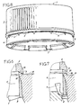
- FIGs 1 to 3 and 8 show a plug 1 which has was made in a mold according to the invention such that shown in Figures 1 to 3 and Figures 6 and 7.
- This plug 1 comprises, in a manner known per se, a bottom 2 extended by a skirt 3 having a thread interior, formed of three threads 4.
- the skirt 3 is connected, at its free end, by a plurality of bridges 5, regularly distributed around its periphery, to a ring inviolability 6. These bridges are breakable under the effect of a certain constraint.
- This plug 1 is intended for equip a container whose neck has a thread with three outer ribs and one annular rib disposed below the thread outside.
- the tamper-evident ring 6 has several tabs 7 regularly distributed.
- the link between the ring and each tab is made by a zone thinned material 8 forming a film hinge, allowing the tongue to be folded inwards.
- the tabs 10 are shown in their final position, as they are on the neck of the container. They are folded towards the bottom 2 of the plug and are substantially parallel to the wall of the tamper evident ring 6 and skirt 3.
- tabs 7 are intended to cooperate with the annular rib of the container neck during the first unscrewing the plug 1. During this first unscrewing, the tabs abut against the annular rib before the complete unscrewing, thus preventing the ring inviolability to pass beyond this rib. In continuing to exert a couple of unscrewing on the skirt 3, the breakable jumpers 5 give way. The ring 6 then remains below of the annular rib and the skirt 3 can be unscrewed, allowing access to the contents of the container.
- the cap has at the edge free from skirt 3, facing the ring tamper-evident 6, three small projections 9 dimension ( Figures 6 to 8). These projections 9 extend over a few millimeters and have a height less than 0.6 millimeter. Each of these projections 9 is located between two successive breakable bridges 5.
- the thread 4 of the skirt has three threads. These have a first end close to the bottom 2 plug and a second end close to the free edge of the skirt 3. There are therefore three ends of the threads on the side of the free edge of the skirt. Each of the projections found substantially halfway between two of these extremities.
- Figures 1 to 3 show in section a mold for make a plug like the one described above.
- This mold has three essential parts: a first part designated by mold base or movable part 20, a second part called stripper part or ring 21 and a third part constituting the core 22 of the mold.
- the inner surface of the bottom of the mold 20 corresponds to the outer surface of the skirt 3 and the bottom 2.
- the internal surface of the feeder ring corresponds to the outer surface of the ring inviolability 6.
- the core 22 gives its shape to the inner surface of the plug, that is to say of the bottom 2, of the skirt 3 and the tamper-evident ring 6.
- the plug 1 has already been molded and the mold is open.
- the deviator ring 21 is moved in the direction of arrow 23 in FIG. 1.
- the core 22 remains stationary.
- the core 22 is removed, according to a method known in itself, by a translational movement of the ring feeder 21, without unscrewing. During this stage, the skirt 3 is deformed. This is to allow free deformation of the skirt 3 as the movable part 20 of the mold is removed before the core is removed. Tabs 7 of the tamper-evident ring 6 are driven by the core 22 and find themselves in a substantially radial position, as shown in Figures 4 and 6.
- the shedding ring 21 is provided with a movement of translation in the direction of arrow 24 in FIGS. 2 and 3, so that the tabs 7 approach the kernel 22.
- Figure 2 illustrates when the tabs 7 come into contact with the core 22 and the Figures 3, 5 and 7 show the core 22 folding the tabs 7 as well as the ejection of the plug from the mold.
- FIGS. 6 and 7 show on an enlarged scale the details A and B of figures 1 and 3 respectively.
- the plan section of these figures goes through a projection 9 of the plug.
- the deviator ring 21 has a rim 25 on which rests on the free edge of the skirt 3. This rim 25 has a notch 26 in which a projection 9.
- the deviator ring 21 has three notches of this type. They are distributed around the periphery of the ledge 25. Each of these notches 26 is located between two breakable bridges 5 neighbors. In addition, these notches are each located approximately halfway between two ends of a thread of the internal thread of the skirt located on the side of the free edge of the skirt.
- a variant is shown on the Figures 4 and 5.
- the tenon link mortise made between the shedding ring 21 and the plug 1 is also not made by placing the post at level of the plug 1 and the mortise at the level of the ring 21, but by placing the post at the level of the shedding ring and mortise at the plug.
- the projections 9 are therefore each replaced by a notch 10 and the notches 26 are each replaced by a projection 27.
- the number of protrusions or of notches on the cap is not limited to three. he there could be two or four. A higher number important is conceivable but may lead to problems, such as jamming the plug in the mold during ejection from the mold or during removal of the nucleus.
- the shape of the plug may be different.
- the bottom of the plug may for example have a skirt intended for come inside the container neck to perfect sealing.
- the shape of the tongues can also be different from that shown in the drawing.
Landscapes
- Engineering & Computer Science (AREA)
- Mechanical Engineering (AREA)
- Manufacturing & Machinery (AREA)
- Closures For Containers (AREA)
- Moulds For Moulding Plastics Or The Like (AREA)
- Cookers (AREA)
- Sampling And Sample Adjustment (AREA)
Abstract
Description
Claims (12)
- Moule pour former un bouchon (1) comportant une jupe cylindrique (3) munie d'au moins un filet de vissage (4) et obturée à une extrémité par un fond (2) ainsi qu'une bague d'inviolabilité (6) reliée à l'extrémité libre de la jupe par des pontets ruptibles (5), la bague d'inviolabilité (6) comportant des languettes (7) destinées à coopérer avec une nervure annulaire située sur le col d'un récipient destiné à recevoir le bouchon, présentant :caractérisé en ce que la bague dévêtrice (21) présente du côté faisant face au fond du moule (20), au niveau du bord inférieur de la jupe et en au moins deux endroits distincts, au moins une encoche (26) et/ou au moins une saillie (27) afin de créer une liaison tenon/mortaise entre la jupe (3) et la bague dévêtrice (21) lors des moulage et démoulage du bouchon (1).une partie mobile ou fond de moule (20) dont la paroi intérieure correspond à la surface extérieure de la jupe et du fond,une partie dévêtisseuse ou bague dévêtrice (21) dont la surface interne correspond à la surface extérieure de la bague d'inviolabilité , etun noyau (22) destiné à être retiré par un mouvement de translation, sans rotation, et dont la surface extérieure correspond à la suface intérieure du fond, de la jupe et de la bague d'inviolabilité,
- Moule selon la revendication 1, caractérisé en ce que la bague dévêtrice (21) comporte trois encoches (26) réparties à la périphérie d'un rebord (25) sur lequel s'appuie le bord inférieur de la jupe en position fermée du moule.
- Moule selon la revendication 1, caractérisé en ce que la bague dévêtrice (21) comporte trois saillies (27) réparties à la périphérie d'un rebord (25) sur lequel s'appuie le bord inférieur de la jupe en position fermée du moule.
- Moule selon l'une des revendications 2 ou 3, dont le noyau (22) comporte trois rainures pour former trois filets sur la face interne de la jupe, caractérisé en ce que chaque encoche (26) ou saillie (27) est placée entre les extrémités, situées du côté de la bague dévêtrice (21), de deux rainures voisines du noyau.
- Moule selon l'une des revendications 1 à 4, caractérisé en ce que chaque encoche (26) ou saillie (27) est placée entre deux entailles voisines du moule prévues pour réaliser les pontets ruptibles (5) reliant la bague d'inviolabilité à la jupe.
- Bouchon (1) comportant une jupe cylindrique (3) munie d'au moins un filet de vissage (4) et obturée à une extrémité par un fond (2) ainsi qu'une bague d'inviolabilité (6) reliée à l'extrémité libre de la jupe par des pontets ruptibles (5), la bague d'inviolabilité (6) comportant des languettes (7) qui, retournées vers l'intérieur et vers le fond du bouchon, sont destinées à coopérer avec une nervure annulaire située sur le col d'un récipient destiné à recevoir le bouchon, caractérisé en ce qu'il présente, au niveau du bord inférieur de la jupe et en au moins deux endroits distincts, au moins une saillie (9) et/ou au moins une encoche (10), de manière à pouvoir créer une liaison tenon/mortaise avec une pièce de forme complémentaire, telle une bague dévêtrice de moule.
- Bouchon selon la revendication 6, caractérisé en ce que les saillies (9), et/ou encoches (10) sont disposées sur des zones correspondant au plus à 30% de la circonférence du bouchon et de préférence à environ 10% de la circonférence du bouchon.
- Bouchon selon l'une quelconque des revendications 6 et 7, caractérisé en ce que la hauteur des saillies (9) ou encoches (10) est inférieure ou égale à 0,6 mm, et de préférence de l'ordre de 0,5 mm.
- Bouchon selon l'une quelconque des revendications 6 à 8, caractérisé en ce que le bord inférieur de la jupe comporte trois saillies (9) réparties à sa périphérie.
- Bouchon selon l'une quelconque des revendications 6 à 8, caractérisé en ce que le bord inférieur de la jupe comporte trois encoches (10) réparties à sa périphérie.
- Bouchon selon l'une des revendications 6 à 9, dont la jupe (3) comporte sur sa face intérieure trois filets, caractérisé en ce que chaque saillie (9) ou encoche (10) est placée entre les extrémités, situées du côté du bord libre de la jupe, de deux filets.
- Bouchon selon l'une des revendications 6 à 11, caractérisé en ce que chaque saillie (9) ou encoche (10) est placée entre deux pontets ruptibles (5) voisins.
Priority Applications (1)
| Application Number | Priority Date | Filing Date | Title |
|---|---|---|---|
| EP98103126A EP0873842A3 (fr) | 1996-01-26 | 1997-01-22 | Moule pour former des bouchons à languettes retournées ainsi que bouchon formé dans un tel moule |
Applications Claiming Priority (3)
| Application Number | Priority Date | Filing Date | Title |
|---|---|---|---|
| FR9601189A FR2744052B1 (fr) | 1996-01-26 | 1996-01-26 | Moule pour former des bouchons a languettes retournees ainsi que bouchon forme dans un tel moule |
| FR9601189 | 1996-01-26 | ||
| PCT/FR1997/000126 WO1997027037A1 (fr) | 1996-01-26 | 1997-01-22 | Moule pour former des bouchons a languettes retournees ainsi que bouchon forme dans un tel moule |
Related Child Applications (1)
| Application Number | Title | Priority Date | Filing Date |
|---|---|---|---|
| EP98103126A Division EP0873842A3 (fr) | 1996-01-26 | 1997-01-22 | Moule pour former des bouchons à languettes retournées ainsi que bouchon formé dans un tel moule |
Publications (2)
| Publication Number | Publication Date |
|---|---|
| EP0876248A1 EP0876248A1 (fr) | 1998-11-11 |
| EP0876248B1 true EP0876248B1 (fr) | 2001-08-01 |
Family
ID=9488707
Family Applications (2)
| Application Number | Title | Priority Date | Filing Date |
|---|---|---|---|
| EP98103126A Withdrawn EP0873842A3 (fr) | 1996-01-26 | 1997-01-22 | Moule pour former des bouchons à languettes retournées ainsi que bouchon formé dans un tel moule |
| EP97901144A Expired - Lifetime EP0876248B1 (fr) | 1996-01-26 | 1997-01-22 | Moule pour former des bouchons a languettes retournees ainsi que bouchon forme dans un tel moule |
Family Applications Before (1)
| Application Number | Title | Priority Date | Filing Date |
|---|---|---|---|
| EP98103126A Withdrawn EP0873842A3 (fr) | 1996-01-26 | 1997-01-22 | Moule pour former des bouchons à languettes retournées ainsi que bouchon formé dans un tel moule |
Country Status (16)
| Country | Link |
|---|---|
| US (2) | US6328175B2 (fr) |
| EP (2) | EP0873842A3 (fr) |
| CN (1) | CN1209768A (fr) |
| AR (1) | AR005554A1 (fr) |
| AT (1) | ATE203701T1 (fr) |
| AU (1) | AU1449197A (fr) |
| BR (1) | BR9707165A (fr) |
| CA (1) | CA2244151A1 (fr) |
| DE (1) | DE69705929T2 (fr) |
| EG (1) | EG21282A (fr) |
| ES (1) | ES2161436T3 (fr) |
| FR (1) | FR2744052B1 (fr) |
| HU (1) | HUP9901143A3 (fr) |
| ID (1) | ID15846A (fr) |
| PL (1) | PL184402B1 (fr) |
| WO (1) | WO1997027037A1 (fr) |
Families Citing this family (27)
| Publication number | Priority date | Publication date | Assignee | Title |
|---|---|---|---|---|
| DK0974529T3 (da) * | 1998-07-18 | 2003-05-26 | Gaplast Gmbh | Prop med spiralnedholder |
| FR2782699B1 (fr) | 1998-09-01 | 2000-10-06 | Crown Cork & Seal Tech Corp | Bouchon a vis presentant une ceinture d'inviolabilite a languettes retournees, moule et procede pour realiser ce bouchon |
| LU90375B1 (fr) * | 1999-03-23 | 2000-09-25 | Alain Franchet | Bouchon - r-cipient - col filet- et - collerette d'accrochage |
| EP1263560B1 (fr) * | 2000-03-16 | 2006-05-03 | Pechiney Plastic Packaging, Inc. | Contenant ameliore, procede et appareil de formation dudit contenant |
| ITBO20000704A1 (it) | 2000-12-04 | 2002-06-04 | Sacmi | Apparecchiatura a giostra per la fabbricazione mediante stampaggio a compressione, di articoli in materiale plastico |
| US6405886B1 (en) * | 2001-02-08 | 2002-06-18 | Rexam Medical Packaging Inc. | Closure having a tamper indicating band |
| ITBO20010228A1 (it) * | 2001-04-18 | 2002-10-18 | Sacmi | Apparecchiatura a giostra per la fabbricazione, mediante stampaggio acompressione, di articoli in materiale plastico |
| US6974046B2 (en) * | 2002-02-14 | 2005-12-13 | Crown Cork & Seal Technologies Corporation | Tamper evident closure with integrated venting and method of manufacturing |
| US7138082B2 (en) * | 2002-12-24 | 2006-11-21 | Graham Packaging Pet Technologies Inc. | Swage-forming of container threads |
| US20050139569A1 (en) * | 2003-12-24 | 2005-06-30 | Larsen W. B. | Swage-forming of container or preform internal threads |
| GB0410731D0 (en) * | 2004-05-13 | 2004-06-16 | Carbonite Corp | Injection moulding plastic container caps |
| US7314366B2 (en) * | 2005-06-17 | 2008-01-01 | Owens-Illinois Closure Inc. | Apparatus and method for inverting a stop flange on a tamper-indicating closure |
| FR2875729B1 (fr) * | 2004-09-27 | 2008-08-15 | Chevalier Soc Par Actions Simp | Piece moulee, son dispositif de moulage et son procede de d'extraction |
| US20070269551A1 (en) * | 2006-05-18 | 2007-11-22 | I-Chung Liao | Mold structure of spike |
| FR2908746B1 (fr) * | 2006-11-20 | 2009-01-09 | Tetra Laval Holdings & Finance | Bouchon pour un col de recipient et procede de fabrication d'un tel bouchon |
| CN102529003B (zh) * | 2012-01-11 | 2014-06-18 | 绍兴县皇冠机械有限公司 | 一种牙膏盖模压成型模具 |
| CN102716939B (zh) * | 2012-04-23 | 2014-07-23 | 钢源(苏州)精密机械有限公司 | 用于校对模具螺纹起始点的治具 |
| CN102886869A (zh) * | 2012-09-22 | 2013-01-23 | 苏州市吴中区木渎华利模具加工店 | 一种化妆瓶内盖成型塑胶模 |
| CN102962954A (zh) * | 2012-11-20 | 2013-03-13 | 常州维卡塑业有限公司 | 用于细牙定位的螺纹脱模模具 |
| CN103737868B (zh) * | 2013-12-31 | 2016-05-11 | 南烽精密机械(深圳)有限公司 | 一种塑料瓶盖模具的脱模机构及其实现方法 |
| FR3021244B1 (fr) * | 2014-05-21 | 2016-06-03 | Tetra Laval Holdings & Finance | Procede de fabrication d'un bouchon pour un col de recipient |
| US9943386B2 (en) * | 2014-05-21 | 2018-04-17 | Align Technology, Inc. | Mold with weakened areas |
| US9943991B2 (en) * | 2014-05-21 | 2018-04-17 | Align Technology, Inc. | Mold with separable features |
| CN107708959B (zh) | 2015-07-08 | 2019-10-01 | 赫斯基注塑系统有限公司 | 用于注塑机的模具堆叠 |
| CN107498793A (zh) * | 2017-09-15 | 2017-12-22 | 四川省宜宾普什模具有限公司 | 瓶盖模内成型及折边结构 |
| CN109571886A (zh) * | 2018-12-20 | 2019-04-05 | 深圳市利众汇科技有限公司 | 瓶盖起模装置 |
| WO2024197380A1 (fr) * | 2023-03-24 | 2024-10-03 | Husky Injection Molding Systems Ltd. | Fermetures et ensembles moules pour la fabrication de fermetures |
Family Cites Families (17)
| Publication number | Priority date | Publication date | Assignee | Title |
|---|---|---|---|---|
| NL6403248A (fr) * | 1964-03-26 | 1965-09-27 | ||
| US3737064A (en) * | 1971-05-17 | 1973-06-05 | C Patel | Pilfer-proof closure for containers |
| CH628302A5 (en) * | 1979-01-19 | 1982-02-26 | Gefit Spa | Method of manufacturing a stopper cap made of plastic material for containers, and stopper produced by this method |
| FR2525565B1 (fr) | 1982-04-23 | 1985-08-09 | Cebal | Capsule de bouchage a vis, en plastique, a bande d'inviolabilite perfectionnee |
| US4529096A (en) * | 1982-06-07 | 1985-07-16 | Consumers Glass Company Limited | Pilferproof cap |
| US4595547A (en) * | 1983-02-18 | 1986-06-17 | Kerr Glass Manufacturing Corporation | Method of manufacturing a tamper evident closure |
| US4526282A (en) * | 1983-05-05 | 1985-07-02 | Sun Coast Plastics, Inc. | Tamper proof closure cap, method, and tool for making same |
| US4697714A (en) * | 1985-02-04 | 1987-10-06 | Tbl Development Corporation | Break-away container closure |
| US5007545A (en) * | 1990-03-15 | 1991-04-16 | Seaquist Closures | Removal resistant member |
| DE4014905C2 (de) | 1990-05-07 | 1994-08-25 | Mannesmann Ag | Vorrichtung zum Schließen von Formen einer Spritzgießmaschine |
| US5281385A (en) * | 1992-10-21 | 1994-01-25 | Sunbeam Plastics Corporation | Injection molding system for threaded tamper indicating closures |
| CA2107041A1 (fr) * | 1993-02-09 | 1994-08-10 | Jose Carvalheiro | Dispositif de fermeture d'un recipient |
| US5803281A (en) * | 1993-06-14 | 1998-09-08 | Oz Worldwide, Inc. | Synthetic resinous container closure having frustoconical sealing surfaces |
| FR2715635B1 (fr) * | 1994-02-02 | 1996-04-12 | Rical Sa | Capsule de bouchage en matière plastique moulée pour la fermeture de récipients à goulot. |
| US5450973A (en) * | 1994-09-22 | 1995-09-19 | Eagle Engraving And Mold Corp. | Tamper-evident closure apparatus |
| US5913436A (en) * | 1995-02-11 | 1999-06-22 | Safety Cap System Ag | Screw cap, specifically comprised of plastic, for closing a bottle or the like |
| US5941403A (en) * | 1995-11-13 | 1999-08-24 | Towns; Edward J. | Closure and method of making same |
-
1996
- 1996-01-26 FR FR9601189A patent/FR2744052B1/fr not_active Expired - Fee Related
-
1997
- 1997-01-22 EP EP98103126A patent/EP0873842A3/fr not_active Withdrawn
- 1997-01-22 US US09/101,432 patent/US6328175B2/en not_active Expired - Fee Related
- 1997-01-22 EP EP97901144A patent/EP0876248B1/fr not_active Expired - Lifetime
- 1997-01-22 DE DE69705929T patent/DE69705929T2/de not_active Expired - Fee Related
- 1997-01-22 WO PCT/FR1997/000126 patent/WO1997027037A1/fr not_active Ceased
- 1997-01-22 AU AU14491/97A patent/AU1449197A/en not_active Abandoned
- 1997-01-22 ES ES97901144T patent/ES2161436T3/es not_active Expired - Lifetime
- 1997-01-22 HU HU9901143A patent/HUP9901143A3/hu unknown
- 1997-01-22 BR BR9707165-0A patent/BR9707165A/pt not_active IP Right Cessation
- 1997-01-22 AT AT97901144T patent/ATE203701T1/de not_active IP Right Cessation
- 1997-01-22 CA CA002244151A patent/CA2244151A1/fr not_active Abandoned
- 1997-01-22 PL PL97328235A patent/PL184402B1/pl not_active IP Right Cessation
- 1997-01-22 CN CN97191892.9A patent/CN1209768A/zh active Pending
- 1997-01-24 AR ARP970100307A patent/AR005554A1/es unknown
- 1997-01-26 EG EG6997A patent/EG21282A/xx active
- 1997-01-27 ID IDP970228A patent/ID15846A/id unknown
-
2001
- 2001-03-16 US US09/809,282 patent/US20010028902A1/en not_active Abandoned
Also Published As
| Publication number | Publication date |
|---|---|
| PL328235A1 (en) | 1999-01-18 |
| FR2744052B1 (fr) | 1998-03-13 |
| CN1209768A (zh) | 1999-03-03 |
| ES2161436T3 (es) | 2001-12-01 |
| US6328175B2 (en) | 2001-12-11 |
| EG21282A (en) | 2001-06-30 |
| US20010002014A1 (en) | 2001-05-31 |
| FR2744052A1 (fr) | 1997-08-01 |
| EP0873842A3 (fr) | 1999-05-19 |
| BR9707165A (pt) | 1999-12-28 |
| US20010028902A1 (en) | 2001-10-11 |
| ATE203701T1 (de) | 2001-08-15 |
| WO1997027037A1 (fr) | 1997-07-31 |
| CA2244151A1 (fr) | 1997-07-31 |
| ID15846A (id) | 1997-08-14 |
| AU1449197A (en) | 1997-08-20 |
| EP0873842A2 (fr) | 1998-10-28 |
| PL184402B1 (pl) | 2002-10-31 |
| DE69705929D1 (de) | 2001-09-06 |
| EP0876248A1 (fr) | 1998-11-11 |
| HUP9901143A3 (en) | 2000-05-29 |
| HUP9901143A2 (hu) | 1999-08-30 |
| DE69705929T2 (de) | 2001-11-22 |
| AR005554A1 (es) | 1999-06-23 |
Similar Documents
| Publication | Publication Date | Title |
|---|---|---|
| WO1997027037A1 (fr) | Moule pour former des bouchons a languettes retournees ainsi que bouchon forme dans un tel moule | |
| CA2147092C (fr) | Capsule a vis pour le bouchage du goulot d'un recipient | |
| EP0682624B1 (fr) | Capsule de bouchage a vis avec bande de garantie | |
| FR2584050A1 (fr) | Recipient tel que bouteille a dispositif de fermeture inviolable comprenant une capsule a vis avec une partie de garantie detachable | |
| CA2151892A1 (fr) | Capsule de bouchage en matiere plastique moulee pour la fermeture de recipients a goulot | |
| FR2634738A1 (fr) | Capuchon de distribution pour un recipient | |
| EP1135302A1 (fr) | Capsule de bouchage pour un recipient a collerette d'accrochage | |
| WO2000012402A1 (fr) | Bouchon a vis | |
| EP0907480B1 (fr) | Procede de fabrication en grande cadence d'assemblages de pieces en matiere plastique | |
| FR2666307A1 (fr) | Bouchon inviolable pour bouteilles. | |
| FR3074785A1 (fr) | Procede de fabrication d'un bouchon de recipient, ebauche de bouchon et bouchon obtenus par la mise en œuvre du procede | |
| EP0355235B1 (fr) | Moule utilisé pour la fabrication d'un bouchon à vis à ceinture d'inviolabilité, du type démoulé par dévissage | |
| FR2701248A1 (fr) | Dispositif de bouchage pour récipient, son procédé de fabrication et récipient équipé d'un tel dispositif. | |
| EP0852205B1 (fr) | Capsule pour le bouchage d'un recipient dont le col est equipe d'une collerette | |
| ZA200206837B (en) | Molded closure with flex areas and method. | |
| FR2542706A1 (fr) | Fermeture avec filetage a entrees multiples | |
| FR2523551A1 (fr) | Dispositif d'inviolabilite pour recipient muni d'une capsule a double jupe | |
| FR3133602A1 (fr) | Bouchon de fermeture d’orifices de versement destiné à des contenants de liquides | |
| FR2707958A1 (fr) | Capsule distributrice en matière plastique pour flacon, tube ou analogue, munie d'un dispositif d'inviolabilité. | |
| EP0012082B1 (fr) | Bouchon inviolable, à vis ou encliquetable, en une seule pièce moulée en matière thermoplastique | |
| FR3140870A1 (fr) | Bouchon a fentes biseautees | |
| FR3095133A1 (fr) | Distributeur de produit fluide | |
| EP4164807B1 (fr) | Organe de fixation de pompe | |
| FR2744988A1 (fr) | Bouchon en matiere plastique comportant une bague d'inviolabilite, ensemble bouchon/recipient, procede de fabrication d'un tel bouchon et procede de realisation d'un tel ensemble bouchon/recipient | |
| FR2659065A1 (fr) | Dispositif de bouchage inviolable a vis pour flacon ou similaire. |
Legal Events
| Date | Code | Title | Description |
|---|---|---|---|
| PUAI | Public reference made under article 153(3) epc to a published international application that has entered the european phase |
Free format text: ORIGINAL CODE: 0009012 |
|
| 17P | Request for examination filed |
Effective date: 19980209 |
|
| AK | Designated contracting states |
Kind code of ref document: A1 Designated state(s): AT BE CH DE DK ES FI FR GB GR IE IT LI LU MC NL PT SE |
|
| AX | Request for extension of the european patent |
Free format text: RO PAYMENT 980706 |
|
| 17Q | First examination report despatched |
Effective date: 19991011 |
|
| GRAG | Despatch of communication of intention to grant |
Free format text: ORIGINAL CODE: EPIDOS AGRA |
|
| GRAG | Despatch of communication of intention to grant |
Free format text: ORIGINAL CODE: EPIDOS AGRA |
|
| GRAH | Despatch of communication of intention to grant a patent |
Free format text: ORIGINAL CODE: EPIDOS IGRA |
|
| GRAH | Despatch of communication of intention to grant a patent |
Free format text: ORIGINAL CODE: EPIDOS IGRA |
|
| GRAA | (expected) grant |
Free format text: ORIGINAL CODE: 0009210 |
|
| AK | Designated contracting states |
Kind code of ref document: B1 Designated state(s): AT BE CH DE DK ES FI FR GB GR IE IT LI LU MC NL PT SE |
|
| AX | Request for extension of the european patent |
Free format text: RO PAYMENT 19980706 |
|
| GBT | Gb: translation of ep patent filed (gb section 77(6)(a)/1977) |
Effective date: 20010706 |
|
| PG25 | Lapsed in a contracting state [announced via postgrant information from national office to epo] |
Ref country code: NL Free format text: LAPSE BECAUSE OF FAILURE TO SUBMIT A TRANSLATION OF THE DESCRIPTION OR TO PAY THE FEE WITHIN THE PRESCRIBED TIME-LIMIT Effective date: 20010801 Ref country code: IE Free format text: LAPSE BECAUSE OF FAILURE TO SUBMIT A TRANSLATION OF THE DESCRIPTION OR TO PAY THE FEE WITHIN THE PRESCRIBED TIME-LIMIT Effective date: 20010801 Ref country code: FI Free format text: LAPSE BECAUSE OF FAILURE TO SUBMIT A TRANSLATION OF THE DESCRIPTION OR TO PAY THE FEE WITHIN THE PRESCRIBED TIME-LIMIT Effective date: 20010801 Ref country code: AT Free format text: LAPSE BECAUSE OF FAILURE TO SUBMIT A TRANSLATION OF THE DESCRIPTION OR TO PAY THE FEE WITHIN THE PRESCRIBED TIME-LIMIT Effective date: 20010801 |
|
| REF | Corresponds to: |
Ref document number: 203701 Country of ref document: AT Date of ref document: 20010815 Kind code of ref document: T |
|
| REG | Reference to a national code |
Ref country code: CH Ref legal event code: EP |
|
| ITF | It: translation for a ep patent filed | ||
| REG | Reference to a national code |
Ref country code: IE Ref legal event code: FG4D Free format text: FRENCH |
|
| REF | Corresponds to: |
Ref document number: 69705929 Country of ref document: DE Date of ref document: 20010906 |
|
| PG25 | Lapsed in a contracting state [announced via postgrant information from national office to epo] |
Ref country code: SE Free format text: LAPSE BECAUSE OF FAILURE TO SUBMIT A TRANSLATION OF THE DESCRIPTION OR TO PAY THE FEE WITHIN THE PRESCRIBED TIME-LIMIT Effective date: 20011101 Ref country code: DK Free format text: LAPSE BECAUSE OF FAILURE TO SUBMIT A TRANSLATION OF THE DESCRIPTION OR TO PAY THE FEE WITHIN THE PRESCRIBED TIME-LIMIT Effective date: 20011101 |
|
| PG25 | Lapsed in a contracting state [announced via postgrant information from national office to epo] |
Ref country code: GR Free format text: LAPSE BECAUSE OF FAILURE TO SUBMIT A TRANSLATION OF THE DESCRIPTION OR TO PAY THE FEE WITHIN THE PRESCRIBED TIME-LIMIT Effective date: 20011102 |
|
| PG25 | Lapsed in a contracting state [announced via postgrant information from national office to epo] |
Ref country code: PT Free format text: LAPSE BECAUSE OF FAILURE TO SUBMIT A TRANSLATION OF THE DESCRIPTION OR TO PAY THE FEE WITHIN THE PRESCRIBED TIME-LIMIT Effective date: 20011105 |
|
| REG | Reference to a national code |
Ref country code: ES Ref legal event code: FG2A Ref document number: 2161436 Country of ref document: ES Kind code of ref document: T3 |
|
| REG | Reference to a national code |
Ref country code: GB Ref legal event code: IF02 |
|
| NLV1 | Nl: lapsed or annulled due to failure to fulfill the requirements of art. 29p and 29m of the patents act | ||
| PG25 | Lapsed in a contracting state [announced via postgrant information from national office to epo] |
Ref country code: LU Free format text: LAPSE BECAUSE OF NON-PAYMENT OF DUE FEES Effective date: 20020122 |
|
| PG25 | Lapsed in a contracting state [announced via postgrant information from national office to epo] |
Ref country code: LI Free format text: LAPSE BECAUSE OF NON-PAYMENT OF DUE FEES Effective date: 20020131 Ref country code: CH Free format text: LAPSE BECAUSE OF NON-PAYMENT OF DUE FEES Effective date: 20020131 Ref country code: BE Free format text: LAPSE BECAUSE OF NON-PAYMENT OF DUE FEES Effective date: 20020131 |
|
| PLBE | No opposition filed within time limit |
Free format text: ORIGINAL CODE: 0009261 |
|
| STAA | Information on the status of an ep patent application or granted ep patent |
Free format text: STATUS: NO OPPOSITION FILED WITHIN TIME LIMIT |
|
| 26N | No opposition filed | ||
| BERE | Be: lapsed |
Owner name: ASTRA PLASTIQUE Effective date: 20020131 |
|
| PG25 | Lapsed in a contracting state [announced via postgrant information from national office to epo] |
Ref country code: MC Free format text: LAPSE BECAUSE OF NON-PAYMENT OF DUE FEES Effective date: 20020801 |
|
| REG | Reference to a national code |
Ref country code: CH Ref legal event code: PL |
|
| PGFP | Annual fee paid to national office [announced via postgrant information from national office to epo] |
Ref country code: ES Payment date: 20050113 Year of fee payment: 9 |
|
| PG25 | Lapsed in a contracting state [announced via postgrant information from national office to epo] |
Ref country code: IT Free format text: LAPSE BECAUSE OF NON-PAYMENT OF DUE FEES Effective date: 20050122 |
|
| REG | Reference to a national code |
Ref country code: HK Ref legal event code: WD Ref document number: 1016534 Country of ref document: HK |
|
| PGFP | Annual fee paid to national office [announced via postgrant information from national office to epo] |
Ref country code: FR Payment date: 20060112 Year of fee payment: 10 |
|
| PGFP | Annual fee paid to national office [announced via postgrant information from national office to epo] |
Ref country code: DE Payment date: 20061214 Year of fee payment: 11 |
|
| GBPC | Gb: european patent ceased through non-payment of renewal fee |
Effective date: 20070122 |
|
| REG | Reference to a national code |
Ref country code: FR Ref legal event code: ST Effective date: 20070930 |
|
| PG25 | Lapsed in a contracting state [announced via postgrant information from national office to epo] |
Ref country code: GB Free format text: LAPSE BECAUSE OF NON-PAYMENT OF DUE FEES Effective date: 20070122 |
|
| REG | Reference to a national code |
Ref country code: ES Ref legal event code: FD2A Effective date: 20070123 |
|
| PG25 | Lapsed in a contracting state [announced via postgrant information from national office to epo] |
Ref country code: FR Free format text: LAPSE BECAUSE OF NON-PAYMENT OF DUE FEES Effective date: 20070131 |
|
| PG25 | Lapsed in a contracting state [announced via postgrant information from national office to epo] |
Ref country code: ES Free format text: LAPSE BECAUSE OF NON-PAYMENT OF DUE FEES Effective date: 20070123 |
|
| PG25 | Lapsed in a contracting state [announced via postgrant information from national office to epo] |
Ref country code: DE Free format text: LAPSE BECAUSE OF NON-PAYMENT OF DUE FEES Effective date: 20080801 |
|
| PGFP | Annual fee paid to national office [announced via postgrant information from national office to epo] |
Ref country code: GB Payment date: 20060116 Year of fee payment: 10 |