EP0876113B1 - Support and cushioning system for footwear - Google Patents
Support and cushioning system for footwear Download PDFInfo
- Publication number
- EP0876113B1 EP0876113B1 EP97921338A EP97921338A EP0876113B1 EP 0876113 B1 EP0876113 B1 EP 0876113B1 EP 97921338 A EP97921338 A EP 97921338A EP 97921338 A EP97921338 A EP 97921338A EP 0876113 B1 EP0876113 B1 EP 0876113B1
- Authority
- EP
- European Patent Office
- Prior art keywords
- chambers
- heel
- forefoot
- resilient insert
- footwear
- Prior art date
- Legal status (The legal status is an assumption and is not a legal conclusion. Google has not performed a legal analysis and makes no representation as to the accuracy of the status listed.)
- Expired - Lifetime
Links
Images



Classifications
-
- A—HUMAN NECESSITIES
- A43—FOOTWEAR
- A43B—CHARACTERISTIC FEATURES OF FOOTWEAR; PARTS OF FOOTWEAR
- A43B13/00—Soles; Sole-and-heel integral units
- A43B13/14—Soles; Sole-and-heel integral units characterised by the constructive form
- A43B13/18—Resilient soles
- A43B13/20—Pneumatic soles filled with a compressible fluid, e.g. air, gas
-
- A—HUMAN NECESSITIES
- A43—FOOTWEAR
- A43B—CHARACTERISTIC FEATURES OF FOOTWEAR; PARTS OF FOOTWEAR
- A43B13/00—Soles; Sole-and-heel integral units
- A43B13/14—Soles; Sole-and-heel integral units characterised by the constructive form
- A43B13/18—Resilient soles
- A43B13/20—Pneumatic soles filled with a compressible fluid, e.g. air, gas
- A43B13/203—Pneumatic soles filled with a compressible fluid, e.g. air, gas provided with a pump or valve
Definitions
- This invention relates generally to footwear, and more particularly to an article of footwear having a system for providing cushioning and support for the comfort of the wearer.
- the human foot is a complex and remarkable piece of machinery, capable of withstanding and dissipating many impact forces.
- An athlete's stride is partly the result of energy which is stored in the flexible tissues of the foot. For example, during a typical walking or running stride, the achilles tendon and the arch stretch and contract, storing energy in the tendons and ligaments. When the restrictive pressure on these elements is released, the stored energy is also released, thereby reducing the burden which must be assumed by the muscles.
- the human foot possesses natural cushioning and rebounding characteristics, the foot alone is incapable of effectively overcoming many of the forces encountered during athletic activity. Unless an individual is wearing shoes which provide proper cushioning and support, the soreness and fatigue associated with athletic activity is more acute, and its onset accelerated. This results in discomfort for the wearer which diminishes the incentive for further athletic activity. Equally important, inadequately cushioned footwear can lead to injuries such as blisters, muscle, tendon and ligament damage, and bone stress fractures. Improper footwear can also lead to other ailments, including back pain.
- Proper footwear should complement the natural functionality of the foot in part by incorporating a sole (typically, an outsole, midsole and insole) which absorbs shocks.
- a sole typically, an outsole, midsole and insole
- the sole should also possess enough resiliency to prevent the sole from being “mushy” or “collapsing,” thereby unduly draining the energy of the wearer.
- a cushioning device which, when unloaded contains air at ambient pressure provides several benefits over similar devices containing pressurized fluid.
- a cushioning device which contains air at ambient pressure will not leak and lose air, because there is no pressure gradient in the resting state.
- the problem with many of these cushioning devices is that they are either too hard or too soft.
- a resilient member that is too hard may provide adequate support when exerting pressure on the member, such as when running. However, the resilient member will likely feel uncomfortable to the wearer when no force is exerted on the member, such as when standing.
- a resilient member that is too soft may feel cushy and comfortable to a wearer when no force is exerted on the member, such as when standing or during casual walking. However, the member will likely not provide the necessary support when force is exerted on the member, such as when running. Further, a resilient member that is too soft may actually drain energy from the wearer.
- WO-A-95 20332 describes a cushioning member for an article of footwear having a series of interconnected chambers filled with air. Impedance means is provided between selected chambers to restrict the flow of air between chambers.
- EP-A-0 714 613 describes an article of footwear including one or more first fluid-containing cushion devices in direct or elastomeric load-transmitting contact with a foot to provide superior comfort, together with one or more second, preferably thicker, fluid-containing cushion devices positioned in a load-transmitting portion of the sole.
- US-A-5 416 986 describes a shoe sole and heel member. Bulges are moulded into the heel portion and the metatarsal region of the sole portion, defining heel and metatarsal cavities. Passageways between the cavities enable air to move back and forth therebetween.
- US-A-4 358 902 describes a thrust-producing shoe sole and heel having fluid-proof cavities located in the heel portion and in the sole portion which underlies the metatarsal ball area of a foot, the cavities being connected by restricted passageways.
- a shoe which incorporates a cushioning system including a means to provide resilient support to the wearer during fast walking and running and to provide adequate cushioning to the wearer during standing and casual walking.
- the resilient insert of the present invention comprises five fluidly interconnected heel chambers, a plurality of fluidly interconnected forefoot chambers and a central connecting passage fluidly interconnecting the chambers.
- the resilient insert is preferably blow moulded from an elastomeric material and contains air at ambient pressure or slightly above ambient pressure.
- the central connecting passage contains an impedance means to restrict the flow of air between the heel chambers and the forefoot chambers.
- an impedance means to restrict the flow of air between the heel chambers and the forefoot chambers.
- the connecting passage is connected at one end thereof to at least one of the heel chambers and connected at the other end to at least one of the forefoot chambers.
- the insert is characterised in that the five heel chambers are disposed in a generally quincunx arrangement.
- an article of footwear comprising the resilient insert incorporated into the sole thereof.
- the resilient insert is placed between an outsole and a midsole of the article of footwear.
- a bladder including a heel chamber, a forefoot chamber and at least one connecting passage fluidly interconnecting the two chambers may be disposed above the midsole of the article of footwear, and provides added cushioning to the wearer's foot.
- the bladder is thermoformed from two sheets of resilient, non-permeable, elastomeric material such that the bladder contains air at slightly above ambient pressure.
- the bladder provides cushioning to the wearer's foot while standing or during casual walking.
- the resilient insert provides added support and cushioning to the wearer's foot during fast walking and running.
- the article of footwear may contain only the resilient insert disposed between the midsole and outsole.
- the article of footwear may contain only the bladder disposed above the midsole.
- the foot of a wearer When stationary, the foot of a wearer is cushioned by the bladder. When the wearer begins a stride, the heel of the wearer's foot typically impacts the ground first. At this time, the weight of the wearer applies downward pressure on the heel portion of the resilient insert, causing the heel chambers to be forced downwardly.
- the heel chambers of the resilient insert are connected via periphery passages. These passages essentially divide the heel portion into a medial region and a lateral region so that the resilient insert is designed geometrically to help compensate for the problem of pronation, the natural tendency of the foot to roll inwardly after heel impact.
- the main distribution of forces on the foot begins adjacent the lateral side of the heel during the "heel strike” phase of the gait, then moves toward the center axis of the foot in the arch area, and then moves to the medial side of the forefoot area during "toe-off.”
- the configuration of the passages between the heel chambers ensures that the air flow within the resilient insert complements such a gait cycle.
- the downward pressure resulting from heel strike causes air within the resilient insert to flow from the medial region into the lateral region.
- the medial region is cushioned first to prevent the wearer's foot from rolling inwardly. Further compression of the heel portion causes the air in the lateral region to be forced forwardly, through the central connecting passage and into the forefoot portion of the resilient insert.
- the flow of air into the forefoot portion causes the forefoot chambers to expand, which slightly raises the forefoot or metatarsal area of the foot.
- the expanded forefoot chambers help cushion the corresponding impact forces.
- the downward pressure caused by the impact forces causes the forefoot chambers to compress, forcing the air therein to be thrust rearwardly through the central connecting passage into the heel portion.
- system of the present invention provides a variable, non-static cushioning, in that the flow of air within the bladder and the resilient insert complements the natural biodynamics of an individual's gait.
- Resilient insert 102 provides continuously modifying cushioning to an article of footwear, such that a wearer's stride forces air within resilient insert 102 to move in a complementary manner with respect to the stride.
- FIG. 1 is a top plan view of resilient insert 102. However, FIG. 1 may in fact be either a top or bottom plan view, as the top and bottom of resilient insert 102 are substantially the same.
- FIG. 2 is a medial side view of resilient insert 102.
- Resilient insert 102 is a three-dimensional structure formed of a suitably resilient material so as to allow resilient insert 102 to compress and expand while resisting breakdown.
- resilient insert 102 may be formed from a thermoplastic elastomer or a thermoplastic olefin.
- Suitable materials used to form resilient insert 102 may include various ranges of the following physical properties: Preferred Lower Limit Preferred Upper Limit Density (Specific Gravity in g/cm 3 ) 0.80 1.35 Modulus @ 300% Elongation (psi) 1,000 6,500 Permanent Set @ 200% Strain (%) 0 55 Compression Set 22 hr/23°C 0 45 Hardness Shore A 70 - Shore D 0 55 Tear Strength (KN/m) 60 600 Permanent Set at Break (%) 0 600
- Thermoplastic Elastomers TPEs
- Thermoplastic Olefins TPOs
- Thermoplastic Vulcanates such as SARLINK from PSM, SANTAPRENE from Monsanto and KRATON from Shell
- Thermoplastic Urethanes TPU's
- PELLETHANE Stock No. 2355-95AE
- TPU available from B.F. Goodrich under the tradename ESTANE
- a TPU available from BASF under the tradename ELASTOLLAN
- resilient insert 102 can be formed from natural rubber compounds. However, these natural rubber compounds currently cannot be blow molded as described below.
- resilient insert 102 is via extrusion blow molding. It will be appreciated by those skilled in the art that the blow molding process is relatively simple and inexpensive. Further, each element of resilient insert 102 is created during the same preferred molding process. This results in a unitary, "one-piece” resilient insert 102, wherein all the unique elements of resilient insert 102 discussed herein are accomplished using the same mold.
- Resilient insert 102 can be extrusion blow molded to create a unitary, "one-piece” component, by any one of the following extrusion blow molding techniques: needle or pin blow molding with subsequent sealing, air entrapped blow molding, pillow blow molding or frame blow molding. These blow molding techniques are known to those skilled in the relevant art.
- resilient insert 102 may be formed from other types of blow molding, such as injection blow molding and stretch blow molding.
- other manufacturing methods can be used to form resilient insert 102, such as thermoforming and sealing, or vacuum forming and sealing.
- Resilient insert 102 is a hollow structure preferably filled with ambient air.
- resilient insert 102 is impermeable to air; i.e., hermetically sealed, such that it is not possible for the ambient air disposed therein to escape upon application of force to resilient insert 102. Naturally, diffusion may occur in and out of resilient insert 102.
- the unloaded pressure within resilient insert 102 is preferably equal to ambient pressure. Accordingly, resilient insert 102 retains its cushioning properties throughout the life of the article of footwear in which it is incorporated. If resilient insert 102 is formed by air entrapment extrusion blow molding, the air inside resilient insert 102 may be slightly higher than ambient pressure (e.g., between 1-5 psi above ambient pressure).
- resilient insert 102 is preferably a unitary member comprising three distinct components: a heel portion 103, a forefoot portion 113, and a central connecting passage 124.
- Heel portion 103 is generally shaped to conform to the outline of the bottom of an individual's heel, and is disposed beneath the heel of a wearer when resilient insert 102 is incorporated within a shoe.
- heel portion 103 includes a plurality of peripheral heel chambers 104, 106, 108, 110 and a central heel air chamber 112.
- Forefoot portion 113 is generally shaped to conform to the forefoot or metatarsal area of a foot, and is disposed beneath a portion of the forefoot of a wearer when incorporated within a shoe.
- forefoot portion 113 includes a plurality of peripheral forefoot chambers 114, 116, 118, 120 and a central forefoot air chamber 122.
- the volume of air within the chambers of forefoot portion 113 is substantially the same as or slightly less than the volume of air within the chambers of heel portion 103.
- impedance means 126 and 128 are disposed within central connecting passage 124. Impedance means 126 and 128 provide a restriction in central connecting passage 124 to restrict the flow of air through central connecting passage 124.
- impedance means 126 and 128 comprise a convolution of connecting passage 124 formed by restriction walls 129 (shown in detail in FIG. 4) placed in central connecting passage 124.
- impedance means 126 is shown as being substantially oval-shaped, and impedance means 128 is shown as being substantially circular.
- impedance means 126 and 128 may comprise numerous shapes or structures.
- the impedance means could be provided by a pinch-off of the material or increased wall thickness of the material.
- Impedance means 126 and 128 prevent air from rushing out of heel chambers 104 - 112 upon heel strike wherein pressure is increased in heel portion 103.
- the shape or structure of impedance means 126 and 128 determines the amount of air that is permitted to pass though central connecting passage 124 at any given time.
- impedance means 126 and 128 are determined by the same mold used to form the remainder of resilient insert 102.
- impedance means 126 and 128 will affect the rate and character of air flow within resilient insert 102, in particular between heel portion 103 and forefoot portion 113 thereof.
- Central connecting passage 124 comprises an elongated passage which connects heel portion 103 to forefoot portion 113.
- Central connecting passage 124 has a first branch 130, connected to forefoot air chamber 114, a second branch 132, connected to central forefoot air chamber 122, and a third branch 134, connected to forefoot air chamber 118.
- These separate branches 130-134 allow air to flow directly into forefoot portion 113 via three separate chambers to distribute air to forefoot chambers 114-122.
- central connecting passage 124 is directly connected to heel air chamber 104 in heel portion 103.
- Forefoot portion 113 may include only one air chamber.
- central connecting passage 124 has only one branch to connect the heel chamber s with the forefoot chamber.
- the number of branches of central connecting passage 124 would also vary accordingly to distribute air to the chambers in forefoot portion 113.
- Heel chambers 104-112 are fluidly interconnected via periphery passages 136.
- Periphery passages 136 allow air to transfer between chambers 104-112 in heel portion 103.
- forefoot chambers 114 and 116 and forefoot chambers 118 and 120 are fluidly interconnected via periphery passages 136, as shown in FIG. 1.
- Periphery passages 136 in heel portion 103 essentially divide heel portion 103 into two regions: a medial region 140 and a lateral region 142.
- Medial region 140 includes heel chambers 108 and 110, while lateral region includes heel chambers 104, 106 and 112.
- a sealed molding port 138 is disposed adjacent the rear of heel portion 103, indicating the area where a molding nozzle was positioned during blow molding.
- the molding nozzle can be positioned at the top of forefoot portion 113 for blow molding resilient insert 102.
- Port 138 may easily be removed (such as by cutting or shaving) during the manufacturing process.
- resilient insert 102 is formed of a suitably resilient material so as to enable heel and forefoot portions 103, 113 to compress and expand.
- Central connecting passage 124 is preferably formed of the same resilient material as the two oppositely-disposed portions adjacent its ends.
- heel chambers 104-112 are slightly larger in volume, than forefoot chambers 114-122. This configuration provides heel chambers 104-112 with a larger volume of air for support and cushioning of the wearer's foot. Since typically during walking and running, the heel of the wearer receives a larger downward force during heel strike, than the forefoot receives during "toe-off", the extra volume of air in heel chambers 104-112 provides the added support and cushioning necessary for the comfort of the wearer.
- FIG. 3 is a cross-section view of resilient insert 102 taken along line 3-3 of FIG. 1.
- periphery passages 136 and central heel air chamber 112 are shown in FIG. 3.
- central heel air chamber is triangular in shape, as opposed to the more oval shape of heel chambers 104-110.
- central heel air chamber 112 is slightly flatter than the remaining heel chambers 104-110. This is because the center of the wearer's heel does not typically encounter as much of a downward force upon heel strike as the outer edges of the wearer's heel, and thus the center of the heel does not require as much cushioning and support.
- FIG. 4 is a cross-section view of resilient insert 102 taken along line 4-4 of FIG. 1.
- impedance means 128 is shown in FIG. 3.
- restriction walls 129 of impedance means 128 form barriers in central connecting passage 124.
- the sides of central connecting passage 124 and impedance means 128 combine to form narrow passages 402 and 404 on either side of impedance means 128.
- Narrow passages 402 and 404 slow the flow of air between heel portion 103 and forefoot portion 113 so that upon heel strike, the air in heel portion 103 gradually flows into forefoot portion 113 to provide adequate support and cushioning to the wearer's foot.
- FIG. 5 shows a cross-sectional view of resilient insert 102 taken along line 5-5 of FIG. 1.
- FIG. 5 shows heel chambers 106 and 108.
- heel air chamber 108 disposed in medial region 140, has a squared edge 502.
- heel air chamber 110 (not visible in FIG. 5) also has a squared edge.
- Squared edge 502 provides extra stiffness to heel chambers 108 and 110 so that these chambers are not compressed as easily during heel strike as the remaining heel chambers 104, 106 and 112.
- squared edges 502 provide added strength to the corners of chambers 108 and 110 so that they are harder to collapse during heel strike.
- Heel chambers 108 and 110 thus provide added support to the wearer's foot in medial region 140 to address the problem of pronation, the natural tendency of the foot to roll inwardly after heel impact.
- the main distribution of forces on the foot begins adjacent the lateral side of the heel during the "heel strike” phase of the gait, then moves toward the center axis of the foot in the arch area, and then moves to the medial side of the forefoot area during "toe-off.”
- Heel chambers 108 and 110 on medial portion 140 address the problem of pronation by preventing the wearer's foot from rolling to the medial side during toe-off by providing the chambers on medial portion 140 with squared edge 502.
- Heel air chamber 106 disposed in lateral region 142, has a rounded edge 504.
- heel air chamber 104 also has a rounded edge.
- Rounded edge 504 allows heel chambers 104 and 106 to gradually collapse under pressure from the heel strike so that air from heel portion 103 begins to flow into central connecting passage 124 and forefoot portion 113. Because lateral portion 142 of heel portion 103 does not require as much support as medial portion 140, rounded edge 504 of heel chambers 104 and 106 provides adequate support to the wearer during heel strike.
- FIGs. 6 and 7 disclose one possible manner of incorporation.
- FIG. 6 is an exploded view showing resilient insert 102 disposed within a sole 602.
- FIG. 7 is a cross-sectional view of sole 602 taken along line 7-7 of FIG. 6.
- Sole 602 includes an outsole 604 and a midsole 606.
- resilient insert 102 is shown disposed between outsole 604 and midsole 606.
- Outsole 604 and midsole 606 are described below with reference to FIGs. 6-9.
- Outsole 604 has an upper surface 608 and a lower surface 610. Further, outsole 604 has a rear tab 612 and a front tab 614. As shown in FIG. 7, upper surface 608 has concave indentations 702 formed therein having upturned side edges 704. Indentations 702 are formed to receive resilient insert 102. Upturned side edges 704 cover the edges of resilient member 102 so that the exterior of resilient insert 102 is not physically exposed to the wearer's surroundings. Further, rear tab 612 and front tab 614 are attached to midsole 606 to prevent the front or rear of resilient insert 102 from being exposed. In one embodiment, outsole 604 is made from a clear crystalline rubber material so that resilient insert 102 is visible to the wearer through outsole 604. Outsole 604 has tread members 616 on lower surface 610. Further, as shown in FIG. 8, outsole 604 has convex indentations 702 on lower surface 610, such that indentations 702 contact the ground during use.
- Midsole 606 has an upper surface 618 and a lower surface 620. As shown in FIGs. 7 and 9, lower surface 620 of midsole 606 has concave indentations 706 formed therein. Indentations 706 are formed to receive resilient insert 102. Midsole 606 also has side edges 708, as shown in FIG. 7. Midsole 606 may be made from EVA foam, as is conventional in the art.
- resilient insert 102 is disposed between outsole 604 and midsole 606, those skilled in the relevant art will appreciate that resilient insert 102 may alternatively be disposed within a cavity formed within midsole 606.
- FIGs. 10-12 show a bladder 1002.
- Bladder 1002 has a rear air chamber 1004 and a front air chamber 1006.
- Bladder 1002 may be manufactured by thermoforming two sheets of plastic film. Each sheet of film used in the thermoforming process is between approximately 6-25 mils (0.15-0.60 mm). Preferably, sheets of film between 10-15 mils (0.25-0.40 mm) are used.
- FIG. 10 shows weld lines 1012 created by the thermoforming manufacturing process.
- Bladder 1002 is made from a relatively soft material, such as urethane film having a hardness of Shore A 80-90, so that bladder 1002 provides added cushioning to the wearer.
- weld lines 1012 form connecting passages 1008 and 1010 which fluidly connect rear and front chambers 1004 and 1006.
- Connecting passages 1008 and 1010 are preferably narrow, approximately 0.030 inch (0.8 mm) - 0.050 inch (1.3 mm) in width and 0.030 inch (0.8mm) - 0.050 inch (1.3 mm) in height, to control the rate of air flow between rear air chamber 1004 and front air chamber 1006 during use.
- Bladder 1002 may be formed by RF welding, heat welding or ultrasonic welding of the urethane film material, instead of thermoforming.
- Bladder 1002 is a hollow structure preferably filled with air at slightly above ambient pressure (e.g., at 1-5 psi above ambient pressure). Bladder 1002 may be impermeable to air, i.e., hermetically sealed, such that it is not possible for the air disposed therein to escape upon application of force to bladder 1002. Naturally, diffusion may occur in and out of bladder 1002. However, because bladder 1002 contains air at only slightly above ambient pressure, it retains its cushioning properties throughout the life of the article of footwear in which it is incorporated.
- FIG. 11 shows a medial side view of bladder 1002. As shown in FIGs. 11 and 12, the portion of bladder 1002 disposed between connecting passages 1008 and 1010, is relatively flat Thus, bladder 1002 provides cushioning for the heel and forefoot portions of the wearer's feet.
- FIG. 12 shows a cross-sectional view of bladder 1002 taken along line 12-12 of FIG. 10. In particular, FIG. 12 shows connecting passages 1008 and 1010 formed by weld lines 1012.
- FIGs. 13 and 14 disclose one possible manner of incorporation of these members within the shoe.
- FIG. 13 is an exploded view showing resilient insert 102 and bladder 1002 as disposed within a shoe.
- FIG. 14 is a cross-sectional view of the shoe taken along line 14-14 of FIG. 13.
- resilient insert 102 is shown disposed between outsole 604 and midsole 606.
- FIG. 14 shows the indentations formed in outsole 604 and midsole 606 to accommodate resilient insert 102, as described above.
- Bladder 1002 is shown disposed above midsole 606 and below a lasting board 1314 and a sockliner 1302.
- Lasting board 1314 may be made from a thick paper material, fibers or textiles, and is disposed between sockliner 1302 and bladder 1002.
- Sockliner 1302 includes a foot supporting surface 1304 having a forefoot region 1306, an arch support region 1308 and a heel region 1310.
- a peripheral wall 1312 extends upwardly from and surrounds a portion of foot supporting surface 1304.
- Moderator 1402 acts as a stiff "plate” between bladder 1002 and the foot of a wearer.
- moderator 1402 is formed of material having a hardness of Shore A 75-95 or Shore C 55-75.
- Potential materials used to form moderator 1402 include EVA, PU, polypropylene, polyethylene, PVC, PFT, fiberboard and other thermoplastics which fall within the aforementioned hardness range.
- the relatively stiff material acts as a moderator for foot strike and diffuses impact forces evenly upon bladder 1002 and resilient insert 102, thereby reducing localized pressures.
- sockliner 1302 may serve as a moderator.
- moderator 1402 may be made from a combination of sockliner 1302, lasting board 1314 and/or one or more of the materials described above having a sufficient hardness to act as a moderator.
- moderator may comprise any structure that accomplishes the above-mentioned moderating function, including part of a midsole, outsole, insole, or a combination of these elements.
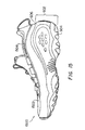
- Resilient insert 102 and bladder 1002 are disposed within an article of footwear 1500, shown in FIG. 15.
- Article of footwear 1500 includes a sole 602 including outsole 604 and midsole 606.
- Resilient insert 102 is disposed between outsole 604 and midsole 606.
- resilient insert 102 is not visible in FIG. 15, in the preferred embodiment, outsole 604 is made from a clear rubber material so that resilient insert 102 is visible.
- bladder 1002 (not visible in FIG. 15) is disposed between midsole 606 and lasting board 1302 (not visible in FIG. 15).
- An upper 1502 is attached to sole 602.
- Upper 1502 has an interior portion 1504. The insole is disposed in interior portion 1504.
- bladder 1002 When stationary, the foot of a wearer is cushioned by bladder 1002. Although the maximum thickness of bladder 1002, is approximately 0.2 inch (5 mm) above the top surface of midsole 606, the bladder produces an unexpectedly high cushioning effect. In one embodiment, bladder 1002, made by RF welding, is between 0.08-0.12 inch (2-3 mm). If bladder 1002 is blow molded, it may be as thick as 0.28-0.31 inch (7-8 mm) when manufactured, and is partially recessed in midsole 606.
- heel of the wearer's foot When the wearer begins a stride, the heel of the wearer's foot typically impacts the ground first. At this time, the weight of the wearer applies downward pressure on heel portion 103 of resilient insert 102, causing heel chambers 104-112 of heel portion 103 to be forced downwardly.
- the configuration of periphery passages 136 between heel chambers 104-112 can help compensate for the problem of pronation, the natural tendency of the foot to roll inwardly after heel impact.
- the main distribution of forces on the foot begins adjacent the lateral side of the heel during the "heel strike” phase of the gait, then moves toward the center axis of the foot in the arch area, and then moves to the medial side of the forefoot area during "toe-off.”
- the configuration of heel chambers 104-112 is incorporated within resilient insert 102 to ensure that the air flow within resilient insert 102 complements such a gait cycle.
- periphery passages 136 within heel portion 103 essentially divide heel portion 103 into two regions: medial region 140 and lateral region 142.
- the downward pressure resulting from heel strike causes air within resilient insert 102 to flow from medial region 140, including heel chambers 108 and 110, into lateral region 142, including heel chambers 104, 106 and 112.
- medial region 142 is cushioned first to prevent the wearer's foot from rolling inwardly.
- Further compression of heel portion 103 causes the air in lateral region 142 to be forced forwardly, through central connecting passage 124, into forefoot portion 113.
- the velocity at which the air flows between heel chambers 104-112 and forefoot chambers 114-122 depends on the structure of central connecting passage 124 and, in particular, the structure of impedance means 126 and 128.
- the flow of air into forefoot portion 113 causes forefoot chambers 114-122 to expand, which slightly raises the forefoot or metatarsal area of the foot. It should be noted that when forefoot chambers 114-122 expand, they assume a somewhat convex shape. When the forefoot of the wearer is placed upon the ground, the expanded forefoot chambers 114-122 help cushion the corresponding impact forces. As the weight of the wearer is applied to the forefoot, the downward pressure caused by the impact forces causes forefoot chambers 114-122 to compress, forcing the air therein to be thrust rearwardly through connecting passage 124 into heel portion 103. Once again, the velocity at which the air flows from forefoot chambers 114-122 to heel chambers 104-112 will be determined by the structure of impedance means 126 and 128.
- resilient insert 102 provides a variable, non-static cushioning, in that the flow of air within resilient insert 102 complements the natural biodynamics of an individual's gait.
- resilient insert 102 especially forefoot portion 113 and connecting passage 124 thereof, be shaped as shown in the figures. Chambers of other shapes may function equally as well.
- bladder 1002 be shaped as shown in FIG.10.
- FIGs. 16-18 show alternative configurations of the bladder. All three of these bladders are formed by thermoforming, as described above with respect to bladder 1002, and contain air at slightly above ambient pressure.
- FIG. 16 shows a second configuration of a bladder 1602.
- Bladder 1602 has a rear chamber 1604, a first front chamber 1606 and a second front chamber 1608.
- First and second front chambers 1606 and 1608 are connected via small passages 1610 formed by weld lines 1616.
- Bladder 1602 has connecting passages 1612 and 1614 formed by weld lines 1616, identical to bladder 1002. Connecting passages 1612 and 1614 connect rear chamber 1604 and first front chamber 1606.
- FIG. 17 shows a third configuration of a bladder 1702.
- Bladder 1702 has a rear chamber 1704 and a plurality of front chambers 1706, 1708, 1710, 1712, 1714 and 1716. Front chamber 1706 and 1716 are connected via a small passage 1718. Similarly, front chambers 1708 and 1714 are connected via a small passage 1720 and front chambers 1710 and 1712 are connected via a small passage 1722.
- Bladder 1702 has connecting passages 1724, 1726 and 1728. Connecting passage 1724 connects rear chamber 1704 and front chamber 1706. Similarly, connecting passage 1726 connects rear chamber 1704 and front chamber 1708, and connecting passage 1728 connects rear chamber 1704 and front chamber 1710.
- FIG. 18 shows a fourth configuration of a bladder 1802.
- Bladder 1802 has a rear chamber 1804 and a plurality of front chambers 1806, 1808 and 1810.
- Bladder 1802 has connecting passages 1812, 1814 and 1816.
- Connecting passage 1812 connects rear chamber 1804 and front chamber 1806.
- connecting passage 1814 connects rear chamber 1804 and front chamber 1808
- connecting passage 1816 connects rear chamber 1804 and front chamber 1810.
- resilient insert 102 comprises an insert which may be positioned within different areas of an article of footwear. Accordingly, although resilient insert 102 is shown as being positioned between outsole 604 and midsole 606 in FIG. 6, it is to be understood that resilient insert 102 may also be positioned within a cavity formed within a midsole or between a midsole and an insole. When positioned between a midsole and an outsole, resilient insert 102 may be visible from the exterior of the shoe. Further, it will be appreciated that the shoe in which resilient insert 102 is incorporated may be constructed so that resilient insert 102 is readily removable and may easily be replaced with another resilient insert. Accordingly, different resilient inserts can be inserted depending upon the physical characteristics of the individual and/or the type of activity for which the shoe is intended.
- resilient insert 102 may also be varied.
- the chambers of resilient insert 102 may be divided such that resilient insert 102 has two cushioning systems which function independently of one another.
- resilient insert 102 provides "multistage" cushioning, wherein the different chambers compress in sequence through the gait cycle.
- An alternative embodiment would include valve means disposed adjacent connecting passage 124, in order to allow the flow rate to be adjusted.
- Another embodiment would be to provide resilient insert 102 with at least two connecting passages 124 with each passage including an interior check-valve.
- the check valves could simply comprise clamping means formed within connecting passages 124.
- each connecting passage 124 would have a check valve to form a one-way passage such that air could only flow in one direction therethrough.
- U.S. Patent No. 5,144,708 which describes therein a one-way valve commonly referred to as a Whoopie valve, available from Dielectric, Industries, Chicopee, Massachusetts.
- fluid may flow from heel portion 103 to forefoot portion 113 through a first connecting passage, and from forefoot portion 113 to heel portion 103 via a second connecting passage.
- the air flow in this embodiment could thus be directed such that it mimics the typical gait cycle discussed above.
- one of the connecting passages could include impedance means which provides laminar air flow, while the other communication chamber could include impedance means to provide turbulent air flow.
- impedance means 126 and 128 will directly affect the velocity of the air as it travels within resilient insert 102.
- the mass flowrate of air within the resilient insert is dependent upon the velocity of the heel strike (in the case of air traveling from the heel chamber to the forefoot chamber). Further, the size and structure of the impedance means directly affects the impulse forces exerted by the air moving within the chambers of the resilient insert. With a given flowrate, the size and structure of the impedance means will dramatically affect the velocity of the air as it travels through the impedance means. Specifically, as the cross-sectional area of the impedance means becomes smaller, the velocity of the air flow becomes greater, as do the impulse forces felt in the forefoot and heel chambers.
- ambient air is disposed within resilient insert 102.
- pressurized air may be disposed within resilient insert 102.
- a slight pressure approximately 1-4 psi above ambient pressure
- other fluid mediums including liquids and large molecule gases, may be disposed within resilient insert 102 and provide the desired support and cushioning thereto. If a fluid medium other than ambient air is used, the structure of the impedance means may be modified in order to effectively provide the character of fluid flow desired.
- resilient insert 102 of the present invention will find its greatest utility in athletic shoes (i.e., those designed for walking, hiking, running, and other athletic activities).
Landscapes
- Footwear And Its Accessory, Manufacturing Method And Apparatuses (AREA)
Abstract
Description
pending, and which is a file wrapper continuation of U.S. Patent Application Number 08/284,646, filed August 11, 1994, now abandoned, which claims priority under 35 U.S.C. § 119 to International Application Number PCT/US94/00895, filed January 26, 1994.
insert 102. However, FIG. 1 may in fact be either a top or bottom plan view, as the top and bottom of
| Preferred Lower Limit | Preferred Upper Limit | |
| Density (Specific Gravity in g/cm3) | 0.80 | 1.35 |
| Modulus @ 300% Elongation (psi) | 1,000 | 6,500 |
| Permanent Set @ 200% Strain (%) | 0 | 55 |
| Compression Set 22 hr/23°C | 0 | 45 |
| Hardness Shore A | 70 | - |
| Shore D | 0 | 55 |
| Tear Strength (KN/m) | 60 | 600 |
| Permanent Set at Break (%) | 0 | 600 |
are accomplished during the preferred blow-molding manufacturing process described above. Accordingly, no complicated or expensive valve means need be attached to
central connecting
1302, lasting
Claims (18)
- A resilient insert (102) for an article of footwear, comprising:characterized in that said five heel chambers (104,106,108,110,112) are disposed in a generally quincunx arrangement.five resilient, non-permeable, heel chambers (104,106,108,110,112) containing air at ambient pressure or above, said five heel chambers (104,106,108,110,112) being fluidly interconnected to each other;a plurality of resilient, non-permeable, forefoot chambers (114,116,118,120,122) containing air at ambient pressure or above, said plurality of forefoot chambers being fluidly interconnected to each other, anda non-permeable connecting passage (124) fluidly connecting at least one of said five heel chambers (104,106,108,110,112) and at least one of said plurality of forefoot chambers (114,116,118,120,122) in a fluid flow restrictive manner;
- A resilient insert (102) as claimed in claim 1, wherein one of said five heel chambers (106) is directly fluidly interconnected with three of said five heel chambers (104,108,112) and each of said three heel chambers (104,108,112) is not directly fluidly interconnected to any of the other of said three heel chambers (104,108,112).
- A resilient insert (102) as claimed in claim 2, wherein said non-permeable connecting passage (124) fluidly connects one of said three heel chambers (104) to said at least one of said plurality of forefoot chambers (114,118,122).
- A resilient insert (102) as claimed in any preceding claim, wherein fluid flow restrictive passages (136) interconnect said heel chambers (104,106,108,110,112).
- A resilient insert (102) as claimed in any preceding claim, wherein said five heel chambers (104,106,108,110) comprise medial region heel chambers (108,110) and lateral region heel chambers (104,106).
- A resilient insert (102) as claimed in any of the preceding claims, wherein said heel chambers (104,106,108,110,112) contain a larger volume of air than said forefoot chambers (114,116,118,120,122).
- A resilient insert (102) as claimed in any of the preceding claims, wherein said forefoot chambers (114,116,118,120,122) comprise a plurality of series-connected medial region forefoot chambers (118,120) and a plurality of series-connected lateral region forefoot chambers (114,116).
- A resilient insert (102) as claimed in claim 7, comprising a further said forefoot chamber (122) between said medial region forefoot chambers (118,120) and said lateral region forefoot chambers (114,116).
- A resilient insert (102) as claimed in any of the preceding claims, wherein said connecting passageway (124) includes impedance means (126,128) restricting fluid flow between said heel chambers (104,106,108,110,112) and said forefoot chambers (114,116,118,120,122).
- A resilient insert (102) as claimed in any of the preceding claims, wherein said connecting passage (124) is elongate and divides at said end adjacent said forefoot chambers into separate elongate branches (130,132,134) which connect to respective ones of said forefoot chambers (114,118,122).
- An article of footwear having a resilient insert (102) as claimed in any of the preceding claims incorporated into the sole thereof.
- An article of footwear as claimed in claim 11, wherein said resilient insert (102) is disposed between a midsole (606) and an outsole (604).
- An article of footwear as claimed in claim 12, wherein said midsole (606) and said outsole (604) have, in the surfaces thereof which are contiguous with said resilient insert (102), formations (702,706) which are complementarily shaped to the chambers (104-112,114-122) of said insert (102).
- An article of footwear as claimed in claim 12 or 13, including a flexible, air filled bladder (1002;1602;1702;1802) above said midsole (606).
- An article of footwear as claimed in claim 14, wherein said bladder (1002) comprises a heel chamber (1004) a forefoot chamber (1006) and a connecting passage (1008,1010) interconnecting said heel and forefoot chambers (1002,1004).
- An article of footwear as claimed in claim 14, wherein said bladder (1602;1702;1802) comprises a single heel chamber (1604;1704;1804) and a plurality of forefoot chambers (1606,1608;1706,1708,1710;1806,1808,1810) each individually fluidly connected to said heel chamber (1604;1704;1804).
- An article of footwear as claimed in claim 14,15 or 16, including a sockliner (1302) disposed above said midsole (606).
- An article of footwear as claimed in claim 17, including a moderator (1314) formed of relatively stiff material disposed beneath said sockliner (1302) and above said bladder (1002;1602;1702;1802).
Applications Claiming Priority (3)
| Application Number | Priority Date | Filing Date | Title |
|---|---|---|---|
| US08/697,895 US5771606A (en) | 1994-10-14 | 1996-09-03 | Support and cushioning system for an article of footwear |
| US697895 | 1996-09-03 | ||
| PCT/US1997/006794 WO1998009546A1 (en) | 1996-09-03 | 1997-04-21 | Support and cushioning system for footwear |
Publications (3)
| Publication Number | Publication Date |
|---|---|
| EP0876113A1 EP0876113A1 (en) | 1998-11-11 |
| EP0876113A4 EP0876113A4 (en) | 1999-12-01 |
| EP0876113B1 true EP0876113B1 (en) | 2003-07-02 |
Family
ID=24803030
Family Applications (1)
| Application Number | Title | Priority Date | Filing Date |
|---|---|---|---|
| EP97921338A Expired - Lifetime EP0876113B1 (en) | 1996-09-03 | 1997-04-21 | Support and cushioning system for footwear |
Country Status (7)
| Country | Link |
|---|---|
| US (2) | US5771606A (en) |
| EP (1) | EP0876113B1 (en) |
| AT (1) | ATE243951T1 (en) |
| AU (1) | AU728402B2 (en) |
| CA (1) | CA2236713C (en) |
| DE (1) | DE69723229T2 (en) |
| WO (1) | WO1998009546A1 (en) |
Cited By (6)
| Publication number | Priority date | Publication date | Assignee | Title |
|---|---|---|---|---|
| KR101379440B1 (en) | 2012-07-04 | 2014-03-28 | (주)한신코리아 | Air cushion insole |
| CN106073016A (en) * | 2016-08-11 | 2016-11-09 | 温州中胤时尚鞋服设计有限公司 | Self-breathing elastic force children's footwear |
| WO2017079252A1 (en) * | 2015-11-03 | 2017-05-11 | Nike Innovate C.V. | Article of footwear including a bladder element having a cushioning component with a single central opening and method of manufacturing |
| US9775407B2 (en) | 2015-11-03 | 2017-10-03 | Nike, Inc. | Article of footwear including a bladder element having a cushioning component with a single central opening and method of manufacturing |
| US10070691B2 (en) | 2015-11-03 | 2018-09-11 | Nike, Inc. | Article of footwear including a bladder element having a cushioning component with a single central opening and a cushioning component with multiple connecting features and method of manufacturing |
| US10905194B2 (en) | 2015-11-03 | 2021-02-02 | Nike, Inc. | Sole structure for an article of footwear having a bladder element with laterally extending tubes and method of manufacturing a sole structure |
Families Citing this family (230)
| Publication number | Priority date | Publication date | Assignee | Title |
|---|---|---|---|---|
| US7107705B2 (en) * | 2002-12-23 | 2006-09-19 | Spenco Medical Corporation | Insole with improved cushioning and anatomical centering device |
| US6453577B1 (en) | 1996-02-09 | 2002-09-24 | Reebok International Ltd. | Support and cushioning system for an article of footwear |
| US5771606A (en) | 1994-10-14 | 1998-06-30 | Reebok International Ltd. | Support and cushioning system for an article of footwear |
| US6230501B1 (en) | 1994-04-14 | 2001-05-15 | Promxd Technology, Inc. | Ergonomic systems and methods providing intelligent adaptive surfaces and temperature control |
| US6505420B1 (en) | 1996-02-09 | 2003-01-14 | Reebok International Ltd. | Cushioning member for an article of footwear |
| TW286269B (en) | 1994-11-28 | 1996-09-21 | Marion Frank Rudy | |
| USD394937S (en) | 1997-01-10 | 1998-06-09 | Reebok International Ltd. | Portion of a shoe sole |
| US5983529A (en) * | 1997-07-31 | 1999-11-16 | Vans, Inc. | Footwear shock absorbing system |
| US6253466B1 (en) * | 1997-12-05 | 2001-07-03 | New Balance Athletic Shoe, Inc. | Shoe sloe cushion |
| USD411912S (en) | 1998-01-30 | 1999-07-13 | Fila Sport S.P.A. | Set of sole inserts |
| US20020121031A1 (en) * | 1998-01-30 | 2002-09-05 | Steven Smith | 2a improvements |
| US6082023A (en) * | 1998-02-03 | 2000-07-04 | Dalton; Edward F. | Shoe sole |
| US6009637A (en) * | 1998-03-02 | 2000-01-04 | Pavone; Luigi Alessio | Helium footwear sole |
| USD448920S1 (en) | 1998-08-06 | 2001-10-09 | Reebok International Ltd. | Portion of a shoe sole |
| USD414597S (en) | 1998-08-26 | 1999-10-05 | Reebok International, Ltd. | Portion of a shoe sole |
| USD423768S (en) * | 1999-02-04 | 2000-05-02 | Reebok International, Ltd. | Shoe upper |
| EP1182944A4 (en) * | 1999-03-16 | 2005-06-22 | Anatomic Res Inc | Removable rounded midsole structures and chambers with computer processor-controlled variable pressure |
| US7334350B2 (en) * | 1999-03-16 | 2008-02-26 | Anatomic Research, Inc | Removable rounded midsole structures and chambers with computer processor-controlled variable pressure |
| US7219449B1 (en) | 1999-05-03 | 2007-05-22 | Promdx Technology, Inc. | Adaptively controlled footwear |
| US6041522A (en) * | 1999-05-26 | 2000-03-28 | E.S. Originals, Inc. | Shoe structure with midsole channel between metatarsal and heel bulges |
| AU5920199A (en) | 1999-09-16 | 2001-04-17 | Andrew A. Bjornson | Support and cushioning system for an article of footwear |
| US6354020B1 (en) * | 1999-09-16 | 2002-03-12 | Reebok International Ltd. | Support and cushioning system for an article of footwear |
| ITMI20000086A1 (en) * | 2000-01-25 | 2001-07-25 | Stefcom Spa | CUSHIONING SOLE STRUCTURE |
| US6374514B1 (en) | 2000-03-16 | 2002-04-23 | Nike, Inc. | Footwear having a bladder with support members |
| US6457262B1 (en) * | 2000-03-16 | 2002-10-01 | Nike, Inc. | Article of footwear with a motion control device |
| US6385864B1 (en) | 2000-03-16 | 2002-05-14 | Nike, Inc. | Footwear bladder with controlled flex tensile member |
| US6402879B1 (en) * | 2000-03-16 | 2002-06-11 | Nike, Inc. | Method of making bladder with inverted edge seam |
| US6571490B2 (en) * | 2000-03-16 | 2003-06-03 | Nike, Inc. | Bladder with multi-stage regionalized cushioning |
| US6430843B1 (en) | 2000-04-18 | 2002-08-13 | Nike, Inc. | Dynamically-controlled cushioning system for an article of footwear |
| USD462158S1 (en) | 2000-06-30 | 2002-09-03 | R. Griggs Group Limited | Portion of a footwear sole |
| US6589614B2 (en) * | 2000-08-17 | 2003-07-08 | Bmc Players | Cushioning device for an athletic shoe |
| US20020194747A1 (en) * | 2001-06-21 | 2002-12-26 | Passke Joel L. | Footwear with bladder filter |
| KR20030018289A (en) * | 2001-08-28 | 2003-03-06 | 조인숙 | slipper of an air-bag structure |
| US6694642B2 (en) * | 2001-09-28 | 2004-02-24 | American Sporting Goods Corporation | Shoe incorporating improved shock absorption and stabilizing elements |
| US6598320B2 (en) * | 2001-09-28 | 2003-07-29 | American Sporting Goods Corporation | Shoe incorporating improved shock absorption and stabilizing elements |
| US6578290B1 (en) * | 2001-10-17 | 2003-06-17 | Meynard Designs, Inc. | Shoe sole |
| US20030150134A1 (en) * | 2002-02-11 | 2003-08-14 | Hardt John C | Anti-roll arch support insole |
| EP1474013A1 (en) * | 2002-02-13 | 2004-11-10 | VINDRIIS, Soren | Method for providing an insole for footwear for increased sensory stimulation and an insole suited for the method |
| US6971193B1 (en) | 2002-03-06 | 2005-12-06 | Nike, Inc. | Bladder with high pressure replenishment reservoir |
| US6751892B2 (en) * | 2002-03-18 | 2004-06-22 | Achidatex Nazareth Elite (1977) Ltd. | Minefield shoe and method for manufacture thereof |
| AU2003203502B2 (en) | 2002-04-10 | 2005-05-19 | Wolverine World Wide, Inc. | Footwear Sole |
| US7426792B2 (en) * | 2002-05-09 | 2008-09-23 | Nike, Inc. | Footwear sole component with an insert |
| US6796056B2 (en) * | 2002-05-09 | 2004-09-28 | Nike, Inc. | Footwear sole component with a single sealed chamber |
| US6754981B1 (en) * | 2002-05-20 | 2004-06-29 | Energaire Corporation | Footwear structure with outsole bulges and midsole bladder |
| US6745499B2 (en) * | 2002-05-24 | 2004-06-08 | Reebok International Ltd. | Shoe sole having a resilient insert |
| US7401419B2 (en) * | 2002-07-31 | 2008-07-22 | Adidas International Marketing B.V, | Structural element for a shoe sole |
| DE102005006267B3 (en) * | 2005-02-11 | 2006-03-16 | Adidas International Marketing B.V. | Shoe sole e.g. for sport shoe, has heel which has bowl or edge having form corresponding to heel of foot and underneath bowl and or edge of heel side panels which are connected to separate rear side panel |
| US7080467B2 (en) | 2003-06-27 | 2006-07-25 | Reebok International Ltd. | Cushioning sole for an article of footwear |
| US7128796B2 (en) * | 2003-07-16 | 2006-10-31 | Nike, Inc. | Footwear with a sole structure incorporating a lobed fluid-filled chamber |
| US7707745B2 (en) * | 2003-07-16 | 2010-05-04 | Nike, Inc. | Footwear with a sole structure incorporating a lobed fluid-filled chamber |
| US7707744B2 (en) * | 2003-07-16 | 2010-05-04 | Nike, Inc. | Footwear with a sole structure incorporating a lobed fluid-filled chamber |
| US7000335B2 (en) * | 2003-07-16 | 2006-02-21 | Nike, Inc. | Footwear with a sole structure incorporating a lobed fluid-filled chamber |
| US6931764B2 (en) | 2003-08-04 | 2005-08-23 | Nike, Inc. | Footwear sole structure incorporating a cushioning component |
| DE10339256A1 (en) * | 2003-08-26 | 2005-04-21 | Li-Chieh Lin | Inflatable system variable integral patterns has the patterns clamped between the outer transparent wall and an inner inflatable cushion |
| US7353625B2 (en) | 2003-11-03 | 2008-04-08 | Reebok International, Ltd. | Resilient cushioning device for the heel portion of a sole |
| US7448522B2 (en) * | 2003-11-11 | 2008-11-11 | Nike, Inc. | Fluid-filled bladder for use with strap |
| US7562469B2 (en) * | 2003-12-23 | 2009-07-21 | Nike, Inc. | Footwear with fluid-filled bladder and a reinforcing structure |
| US7156787B2 (en) * | 2003-12-23 | 2007-01-02 | Nike, Inc. | Inflatable structure and method of manufacture |
| US7086179B2 (en) * | 2003-12-23 | 2006-08-08 | Nike, Inc. | Article of footwear having a fluid-filled bladder with a reinforcing structure |
| US7100310B2 (en) * | 2003-12-23 | 2006-09-05 | Nike, Inc. | Article of footwear having a fluid-filled bladder with a reinforcing structure |
| US7556846B2 (en) * | 2003-12-23 | 2009-07-07 | Nike, Inc. | Fluid-filled bladder with a reinforcing structure |
| US7086180B2 (en) * | 2003-12-23 | 2006-08-08 | Nike, Inc. | Article of footwear having a fluid-filled bladder with a reinforcing structure |
| US7141131B2 (en) * | 2003-12-23 | 2006-11-28 | Nike, Inc. | Method of making article of footwear having a fluid-filled bladder with a reinforcing structure |
| US7383648B1 (en) | 2004-02-23 | 2008-06-10 | Reebok International Ltd. | Inflatable support system for an article of footwear |
| US7448150B1 (en) * | 2004-02-26 | 2008-11-11 | Reebok International Ltd. | Insert with variable cushioning and support and article of footwear containing same |
| US7334351B2 (en) * | 2004-06-07 | 2008-02-26 | Energy Management Athletics, Llc | Shoe apparatus with improved efficiency |
| US7622014B2 (en) | 2005-07-01 | 2009-11-24 | Reebok International Ltd. | Method for manufacturing inflatable footwear or bladders for use in inflatable articles |
| US7533477B2 (en) | 2005-10-03 | 2009-05-19 | Nike, Inc. | Article of footwear with a sole structure having fluid-filled support elements |
| US7409779B2 (en) * | 2005-10-19 | 2008-08-12 | Nike, Inc. | Fluid system having multiple pump chambers |
| US7523565B1 (en) * | 2006-02-21 | 2009-04-28 | Kuang Ming Chen | Shoes comprising air cushioning system, air lightweight system, and air pressure alert system |
| US8968633B2 (en) * | 2006-05-03 | 2015-03-03 | Nike, Inc. | Method for manufacturing footwear last, and footwear last manufactured by the method |
| US7784196B1 (en) | 2006-12-13 | 2010-08-31 | Reebok International Ltd. | Article of footwear having an inflatable ground engaging surface |
| US7694438B1 (en) | 2006-12-13 | 2010-04-13 | Reebok International Ltd. | Article of footwear having an adjustable ride |
| US8256141B2 (en) * | 2006-12-13 | 2012-09-04 | Reebok International Limited | Article of footwear having an adjustable ride |
| US7934521B1 (en) | 2006-12-20 | 2011-05-03 | Reebok International, Ltd. | Configurable fluid transfer manifold for inflatable footwear |
| US8230874B2 (en) * | 2006-12-20 | 2012-07-31 | Reebok International Limited | Configurable fluid transfer manifold for inflatable footwear |
| US8414275B1 (en) | 2007-01-11 | 2013-04-09 | Reebok International Limited | Pump and valve combination for an article of footwear incorporating an inflatable bladder |
| US7810255B2 (en) * | 2007-02-06 | 2010-10-12 | Nike, Inc. | Interlocking fluid-filled chambers for an article of footwear |
| US7950169B2 (en) * | 2007-05-10 | 2011-05-31 | Nike, Inc. | Contoured fluid-filled chamber |
| US7841108B2 (en) * | 2007-05-29 | 2010-11-30 | Nike, Inc. | Article of footwear with visible indicia |
| US7849611B2 (en) * | 2007-06-13 | 2010-12-14 | Dean Christopher N | Shoe with system for preventing or limiting ankle sprains |
| CN101742938B (en) * | 2007-09-14 | 2012-03-21 | 斯彭科医疗公司 | Triple density gel insole |
| US8978273B2 (en) | 2007-10-19 | 2015-03-17 | Nike, Inc. | Article of footwear with a sole structure having fluid-filled support elements |
| US8241450B2 (en) | 2007-12-17 | 2012-08-14 | Nike, Inc. | Method for inflating a fluid-filled chamber |
| US20090152774A1 (en) * | 2007-12-17 | 2009-06-18 | Nike, Inc. | Method For Molding A Fluid-Filled Structure |
| US8863408B2 (en) * | 2007-12-17 | 2014-10-21 | Nike, Inc. | Article of footwear having a sole structure with a fluid-filled chamber |
| US8178022B2 (en) * | 2007-12-17 | 2012-05-15 | Nike, Inc. | Method of manufacturing an article of footwear with a fluid-filled chamber |
| US8572867B2 (en) | 2008-01-16 | 2013-11-05 | Nike, Inc. | Fluid-filled chamber with a reinforcing element |
| US8341857B2 (en) | 2008-01-16 | 2013-01-01 | Nike, Inc. | Fluid-filled chamber with a reinforced surface |
| US7966749B2 (en) * | 2008-02-08 | 2011-06-28 | Reebok International Ltd. | Multi-chamber cushion for footwear |
| EP2247209B1 (en) | 2008-02-27 | 2017-08-23 | Ecco Sko A/S | Midsole for a shoe, in particular a running shoe |
| US20090293305A1 (en) * | 2008-05-30 | 2009-12-03 | St Ip, Llc | Full length airbag |
| USD597287S1 (en) | 2008-09-26 | 2009-08-04 | Reebok International Ltd. | Shoe sole |
| US8424221B2 (en) * | 2009-04-01 | 2013-04-23 | Reebok International Limited | Training footwear |
| US8307569B2 (en) * | 2009-04-01 | 2012-11-13 | Reebok International Limited | Training footwear |
| US20100275468A1 (en) * | 2009-04-29 | 2010-11-04 | Brown Shoe Company, Inc. | Air circulating footbed and method thereof |
| US8650775B2 (en) * | 2009-06-25 | 2014-02-18 | Nike, Inc. | Article of footwear having a sole structure with perimeter and central elements |
| WO2012109612A2 (en) * | 2011-02-11 | 2012-08-16 | Code Footwear, Llc | Reconfigurable apparel manufacture and business processes |
| US20110072684A1 (en) * | 2009-09-25 | 2011-03-31 | Aci International | Support structures in footwear |
| USD671304S1 (en) | 2009-09-28 | 2012-11-27 | Reebok International Limited | Shoe sole |
| US20110126422A1 (en) * | 2009-12-02 | 2011-06-02 | Brown Shoe Company, Inc. | Shoe sole with compressible protruding element |
| US9987814B2 (en) | 2013-02-21 | 2018-06-05 | Nike, Inc. | Method of co-molding |
| US9119439B2 (en) * | 2009-12-03 | 2015-09-01 | Nike, Inc. | Fluid-filled structure |
| US9894959B2 (en) | 2009-12-03 | 2018-02-20 | Nike, Inc. | Tethered fluid-filled chamber with multiple tether configurations |
| US9801428B2 (en) | 2009-12-03 | 2017-10-31 | Nike, Inc. | Tethered fluid-filled chamber with multiple tether configurations |
| US9521877B2 (en) * | 2013-02-21 | 2016-12-20 | Nike, Inc. | Article of footwear with outsole bonded to cushioning component and method of manufacturing an article of footwear |
| US9750307B2 (en) * | 2013-02-21 | 2017-09-05 | Nike, Inc. | Article of footwear having a sole structure including a fluid-filled chamber and an outsole, the sole structure, and methods for manufacturing |
| US8991072B2 (en) * | 2010-02-22 | 2015-03-31 | Nike, Inc. | Fluid-filled chamber incorporating a flexible plate |
| US8782924B2 (en) | 2010-05-11 | 2014-07-22 | Nike, Inc. | Article of footwear having a sole structure with a framework-chamber arrangement |
| JP5855648B2 (en) | 2010-06-25 | 2016-02-09 | スペンコ、メディカル、コーパレイシャン | Shoe insole with curved support |
| KR101008305B1 (en) | 2010-07-05 | 2011-01-14 | 김성순 | Shoe insole with airbag |
| GB201015073D0 (en) * | 2010-09-10 | 2010-10-27 | Harrison Spinks Beds Ltd | Resilient pad for footwear |
| USD677041S1 (en) | 2010-09-20 | 2013-03-05 | The Rockport Company, Llc | Heel of a shoe sole |
| USD677866S1 (en) | 2010-09-24 | 2013-03-19 | Reebok International Limited | Shoe |
| US8572786B2 (en) | 2010-10-12 | 2013-11-05 | Reebok International Limited | Method for manufacturing inflatable bladders for use in footwear and other articles of manufacture |
| USD675002S1 (en) | 2010-11-02 | 2013-01-29 | Reebok International Limited | Shoe sole |
| USD677040S1 (en) | 2010-11-17 | 2013-03-05 | Reebok International Limited | Shoe |
| US10010131B2 (en) | 2011-02-02 | 2018-07-03 | Implus Footcare, Llc | Flow insole |
| US10010136B2 (en) * | 2011-03-16 | 2018-07-03 | Nike, Inc. | Footwear sole structure incorporating a plurality of chambers |
| WO2012126489A1 (en) * | 2011-03-24 | 2012-09-27 | Msc Schweiz Ag | Sole construction having an air pumping device |
| USD714036S1 (en) | 2011-03-31 | 2014-09-30 | Adidas Ag | Shoe sole |
| USD695501S1 (en) * | 2011-07-08 | 2013-12-17 | Ben Melech Yehudah | Shoe sole with animal paws |
| US10034517B2 (en) | 2011-12-29 | 2018-07-31 | Reebok International Limited | Sole and article of footwear having a pod assembly |
| US10016017B2 (en) | 2011-12-29 | 2018-07-10 | Reebok International Limited | Sole and article of footwear having a pod assembly |
| US9609913B2 (en) | 2011-12-29 | 2017-04-04 | Reebok International Limited | Sole and article of footwear having a pod assemby |
| US8914994B2 (en) | 2012-03-02 | 2014-12-23 | Nike, Inc. | Guitar-shaped bladder for footwear |
| US9615627B2 (en) * | 2012-03-22 | 2017-04-11 | Nike, Inc. | Sole structure configured to allow relative heel/forefoot motion |
| USD719331S1 (en) | 2012-03-23 | 2014-12-16 | Reebok International Limited | Shoe |
| USD711636S1 (en) | 2012-03-23 | 2014-08-26 | Reebok International Limited | Shoe |
| US9131748B2 (en) | 2012-04-24 | 2015-09-15 | Nike, Inc. | Sole assembly with gas and viscous fluid-filled bladder assembly |
| US9420847B2 (en) * | 2012-04-25 | 2016-08-23 | Nike, Inc. | Article of footwear with bladder and method of manufacturing the same |
| USD693551S1 (en) | 2012-07-10 | 2013-11-19 | Reebok International Limited | Shoe |
| USD693550S1 (en) | 2012-07-10 | 2013-11-19 | Reebok International Limited | Shoe |
| CN104918509A (en) | 2012-08-31 | 2015-09-16 | 斯彭科医疗公司 | Basketball insole |
| USD722750S1 (en) | 2012-09-07 | 2015-02-24 | Reebok International Limited | Shoe |
| US10856612B2 (en) | 2012-09-20 | 2020-12-08 | Nike, Inc. | Sole structures and articles of footwear having plate moderated fluid-filled bladders and/or foam type impact force attenuation members |
| US9456658B2 (en) | 2012-09-20 | 2016-10-04 | Nike, Inc. | Sole structures and articles of footwear having plate moderated fluid-filled bladders and/or foam type impact force attenuation members |
| US10849387B2 (en) * | 2012-09-20 | 2020-12-01 | Nike, Inc. | Sole structures and articles of footwear having plate moderated fluid-filled bladders and/or foam type impact force attenuation members |
| US20140137437A1 (en) * | 2012-11-20 | 2014-05-22 | Wolverine World Wide, Inc. | Adjustable footwear sole with bladder |
| US9380832B2 (en) | 2012-12-20 | 2016-07-05 | Nike, Inc. | Article of footwear with fluid-filled chamber lacking an inflation channel and method for making the same |
| US9981437B2 (en) * | 2013-02-21 | 2018-05-29 | Nike, Inc. | Article of footwear with first and second outsole components and method of manufacturing an article of footwear |
| US10178891B2 (en) | 2013-03-22 | 2019-01-15 | Reebok International Limited | Sole and article of footwear having a pod assembly |
| US20140331525A1 (en) * | 2013-05-13 | 2014-11-13 | Ariel West | Footwear with plantar misting system |
| US10945488B2 (en) * | 2013-08-09 | 2021-03-16 | Reebok International Limited | Article of footwear with extruded components |
| US9320320B1 (en) | 2014-01-10 | 2016-04-26 | Harry A. Shamir | Exercise shoe |
| KR101433564B1 (en) * | 2014-06-10 | 2014-08-27 | 정진 | Shoe midsole assembly equipped airbag system |
| US9204687B1 (en) | 2014-07-24 | 2015-12-08 | Shlomo Piontkowski | Footwear with dynamic arch system |
| US9392842B2 (en) | 2014-07-24 | 2016-07-19 | Shlomo Piontkowski | Footwear with dynamic arch system |
| US10827798B2 (en) | 2014-07-24 | 2020-11-10 | Shlomo Piontkowski | Footwear with dynamic arch system |
| US20160021976A1 (en) | 2014-07-24 | 2016-01-28 | Shlomo Piontkowski | Footwear with Dynamic Arch System |
| US9857788B2 (en) | 2014-07-24 | 2018-01-02 | Shlomo Piontkowski | Adjustable height sole |
| WO2016115134A1 (en) * | 2015-01-12 | 2016-07-21 | Under Armour, Inc. | Sole structure with bottom-loaded compression |
| US10624417B2 (en) | 2015-03-09 | 2020-04-21 | Nike, Inc. | Article of footwear with outsole bonded to cushioning component and method of manufacturing an article of footwear |
| WO2016144648A1 (en) * | 2015-03-09 | 2016-09-15 | Nike Innovate C.V. | Method of co-molding |
| WO2016144649A1 (en) * | 2015-03-09 | 2016-09-15 | Nike Innovate C.V. | A sole structure for an article of footwear, including a fluid-filled chamber and an outsole, and methods for manufacturing |
| US9833038B2 (en) * | 2015-03-19 | 2017-12-05 | Nike, Inc. | Multi-density midsole and plate system |
| EP3285608B1 (en) | 2015-04-24 | 2019-05-22 | Nike Innovate C.V. | Footwear sole structure having bladder with integrated outsole |
| US10709203B2 (en) | 2015-05-28 | 2020-07-14 | Implus Footcare, Llc | Contoured support shoe insole |
| KR20180015122A (en) | 2015-05-28 | 2018-02-12 | 임플러스 풋케어 엘엘씨 | Shoe insole |
| WO2016191505A1 (en) | 2015-05-28 | 2016-12-01 | Spenco Medical Corporation | Contoured support shoe insole |
| WO2016191498A1 (en) | 2015-05-28 | 2016-12-01 | Spenco Medical Corporation | Contoured support shoe insole |
| US9820531B2 (en) | 2015-05-29 | 2017-11-21 | Nike, Inc. | Footwear including an incline adjuster |
| USD771921S1 (en) | 2015-06-25 | 2016-11-22 | Implus Footcare, Llc | Shoe insole |
| USD761543S1 (en) | 2015-06-25 | 2016-07-19 | Spenco Medical Corporation | Shoe insole |
| USD762368S1 (en) | 2015-06-25 | 2016-08-02 | Spenco Medical Corporation | Shoe insole |
| USD758058S1 (en) | 2015-06-25 | 2016-06-07 | Spenco Medical Corporation | Heel cup |
| USD762367S1 (en) | 2015-06-25 | 2016-08-02 | Spenco Medical Corporation | Shoe insole |
| USD762366S1 (en) | 2015-06-25 | 2016-08-02 | Spenco Medical Corporation | Shoe insole |
| USD766560S1 (en) | 2015-06-25 | 2016-09-20 | Implus Footcare, Llc | Shoe insole |
| USD797430S1 (en) | 2015-07-15 | 2017-09-19 | Implus Footcare, Llc | Shoe insole |
| USD797429S1 (en) | 2015-07-15 | 2017-09-19 | Implus Footcare, Llc | Shoe insole |
| USD797428S1 (en) | 2015-07-15 | 2017-09-19 | Implus Footcare, Llc | Shoe insole |
| CN105167321B (en) * | 2015-09-02 | 2017-03-22 | 福建鸿星尔克体育用品有限公司 | Bionic functional soles and running shoes |
| USD771922S1 (en) | 2015-09-15 | 2016-11-22 | Implus Footcare, Llc | Shoe insole |
| USD778567S1 (en) | 2015-09-17 | 2017-02-14 | Implus Footcare, Llc | Shoe insole |
| USD814750S1 (en) | 2015-09-25 | 2018-04-10 | Fourfoot, Llc | Sandal |
| USD778040S1 (en) | 2015-09-25 | 2017-02-07 | Implus Footcare, Llc | Shoe insole |
| US10932523B2 (en) | 2015-11-30 | 2021-03-02 | Nike, Inc. | Electrorheological fluid structure with attached conductor and method of fabrication |
| DE102016000490A1 (en) | 2016-01-13 | 2017-07-13 | Bauerfeind Ag | Epicondylitis pad |
| EP3669687B1 (en) * | 2016-03-15 | 2022-04-13 | NIKE Innovate C.V. | Sole structure for article of footwear |
| WO2017160729A1 (en) | 2016-03-15 | 2017-09-21 | Nike Innovate C.V. | Article of footwear and method of manufacturing an article of footwear |
| JP1581802S (en) | 2016-03-23 | 2017-07-24 | ||
| JP1584710S (en) | 2016-11-02 | 2017-08-28 | ||
| WO2018098463A1 (en) * | 2016-11-28 | 2018-05-31 | The Board Of Regents Of The University Of Texas System | Dual-layer insole apparatuses for diabetic foot lesion prevention and related methods |
| CN110325071B (en) * | 2017-04-11 | 2021-08-20 | 耐克创新有限合伙公司 | Article of footwear comprising a multi-part sole structure |
| CN113812719B (en) | 2017-05-18 | 2023-06-27 | 耐克创新有限合伙公司 | Cushioning article with tensile member and method of making cushioning article |
| JP2020519350A (en) | 2017-05-18 | 2020-07-02 | ナイキ イノベイト シーブイ | Articulated cushioning product with tensile component and method of making the cushioning product |
| WO2019046516A1 (en) | 2017-08-31 | 2019-03-07 | Nike Innovate C.V. | Footwear including an incline adjuster |
| JP6843296B2 (en) * | 2017-08-31 | 2021-03-17 | ナイキ イノベイト シーブイ | Inclined adjuster with multiple individual chambers |
| KR102330563B1 (en) | 2017-10-13 | 2021-12-01 | 나이키 이노베이트 씨.브이. | Footwear midsole with electrorheological fluid housing |
| USD852480S1 (en) | 2017-11-09 | 2019-07-02 | Reebok International Limited | Sole |
| TWI848229B (en) * | 2017-12-14 | 2024-07-11 | 荷蘭商耐克創新有限合夥公司 | Sole structure for article of footwear and article of footwear incorporating the same |
| TWI737945B (en) * | 2017-12-14 | 2021-09-01 | 荷蘭商耐克創新有限合夥公司 | Sole structure for article of footwear |
| KR102643930B1 (en) * | 2018-05-30 | 2024-03-05 | 나이키 이노베이트 씨.브이. | Footwear sole structure with bladder |
| WO2019231970A1 (en) | 2018-05-31 | 2019-12-05 | Nike Innovate C.V. | Fluid flow control devices usable in adjustable foot support systems |
| KR102497958B1 (en) | 2018-05-31 | 2023-02-08 | 나이키 이노베이트 씨.브이. | Adjustable foot support system with fluid-filled bladder chamber |
| EP4563032A3 (en) * | 2018-11-29 | 2025-08-06 | NIKE Innovate C.V. | Foot support systems including fluid filled bladders with movement of fluid between bladders |
| US12096823B1 (en) * | 2018-11-30 | 2024-09-24 | Under Armour, Inc. | Article of footwear |
| EP4368053A3 (en) * | 2019-01-02 | 2024-07-17 | Nike Innovate C.V. | Sole structure for article of footwear |
| CN113329655B (en) | 2019-01-31 | 2022-09-23 | 耐克创新有限合伙公司 | Sole structure and article of footwear with fluid-filled bladder element |
| US12171300B2 (en) * | 2019-03-28 | 2024-12-24 | Nike, Inc. | Sole structure of an article of footwear |
| US11291270B2 (en) | 2019-11-15 | 2022-04-05 | Reebok International Limited | Article of footwear having cushioning system |
| US11638463B2 (en) * | 2019-11-19 | 2023-05-02 | Nike, Inc. | Sole structure for article of footwear |
| EP4494511A3 (en) * | 2019-11-19 | 2025-04-09 | Nike Innovate C.V. | Sole structure for an article of footwear |
| USD934542S1 (en) * | 2020-02-06 | 2021-11-02 | Acushnet Company | Golf shoe outsole |
| WO2021243135A1 (en) * | 2020-05-28 | 2021-12-02 | Nike Innovate C.V. | Foot support systems including fluid movement controllers and adjustable foot support pressure |
| US20210368888A1 (en) * | 2020-06-01 | 2021-12-02 | Patrick Rome | Face shield with adjustable tensioning |
| US11633010B2 (en) * | 2020-07-22 | 2023-04-25 | Nike, Inc. | Sole structure for article of footwear and article of footwear |
| US11896080B2 (en) * | 2020-08-12 | 2024-02-13 | Nike, Inc. | Sole structure for article of footwear |
| USD930346S1 (en) * | 2020-08-26 | 2021-09-14 | Nike, Inc. | Shoe |
| USD955728S1 (en) * | 2020-08-27 | 2022-06-28 | Nike, Inc. | Shoe |
| US12102169B2 (en) * | 2020-12-18 | 2024-10-01 | Genesco Inc. | Chassis system for footwear |
| USD929725S1 (en) * | 2021-01-13 | 2021-09-07 | Nike, Inc. | Cushioning device for footwear |
| USD929724S1 (en) * | 2021-01-13 | 2021-09-07 | Nike, Inc. | Cushioning device for footwear |
| USD929723S1 (en) * | 2021-01-13 | 2021-09-07 | Nike, Inc. | Cushioning device for footwear |
| USD929100S1 (en) * | 2021-01-13 | 2021-08-31 | Nike, Inc. | Cushioning device for footwear |
| USD929726S1 (en) * | 2021-01-13 | 2021-09-07 | Nike, Inc. | Cushioning device for footwear |
| US12178284B2 (en) * | 2021-05-28 | 2024-12-31 | Nike, Inc. | Sole structure for article of footwear |
| US12290135B2 (en) * | 2021-05-28 | 2025-05-06 | Nike, Inc. | Sole structure for article of footwear |
| US12250987B2 (en) | 2021-05-28 | 2025-03-18 | Nike, Inc. | Sole structure for article of footwear |
| US20220395056A1 (en) * | 2021-06-11 | 2022-12-15 | Nike, Inc. | Sole structure for article of footwear |
| WO2022271460A1 (en) * | 2021-06-24 | 2022-12-29 | Matmarket, LLC | Footbeds with improved cushioning, stability and comfort and methods of making same |
| US12369686B2 (en) * | 2021-08-27 | 2025-07-29 | Jim de Wilde | Tripod running shoes |
| US20230127595A1 (en) * | 2021-10-25 | 2023-04-27 | Nike, Inc. | Sole structure for article of footwear |
| CN119317374A (en) | 2022-07-28 | 2025-01-14 | 耐克创新有限合伙公司 | Article of footwear having a bladder at the foot-facing surface of a foam midsole |
| US12426679B2 (en) | 2022-09-01 | 2025-09-30 | Nike, Inc. | Article of footwear with stacked forefoot bladders |
| US20240180291A1 (en) * | 2022-12-05 | 2024-06-06 | Reebok International Limited | Article of footwear having a reflectively symmetrical fluid cushioning system |
| US12582196B2 (en) | 2023-06-30 | 2026-03-24 | Nike, Inc. | Article of footwear including a sole structure |
| KR200499350Y1 (en) * | 2023-07-10 | 2025-07-10 | 최경덕 | Air pocket insole with improved breathability |
| US20250288059A1 (en) * | 2024-03-14 | 2025-09-18 | Nike, Inc. | Sole structure for an article of footwear |
Family Cites Families (47)
| Publication number | Priority date | Publication date | Assignee | Title |
|---|---|---|---|---|
| US1605985A (en) * | 1926-11-09 | rasmussen | ||
| US1069001A (en) * | 1913-01-14 | 1913-07-29 | William H Guy | Cushioned sole and heel for shoes. |
| GB338266A (en) * | 1929-09-13 | 1930-11-20 | Charles Houldsworth Rayne | Improvements in foot arch supports |
| FR720257A (en) * | 1930-08-18 | 1932-02-17 | Pneumatic sole for shoes and shoes | |
| US2080499A (en) * | 1935-10-31 | 1937-05-18 | Levi L Gilbert | Insole for shoes |
| US2266476A (en) * | 1940-07-02 | 1941-12-16 | Walter A Riess | Shoe |
| DE820869C (en) * | 1949-02-26 | 1951-11-12 | Erna Loeffler | Shoe insole with air cushions |
| US3120712A (en) * | 1961-08-30 | 1964-02-11 | Menken Lester Lambert | Shoe construction |
| US3225463A (en) * | 1962-10-12 | 1965-12-28 | Charles E Burnham | Air ventilated insole |
| US3469576A (en) * | 1966-10-05 | 1969-09-30 | Henry M Smith | Footwear |
| US4100686A (en) * | 1977-09-06 | 1978-07-18 | Sgarlato Thomas E | Shoe sole construction |
| DE2800359A1 (en) * | 1978-01-05 | 1979-07-12 | Will Peter Dr | FOOTBED FOR ACTIVE FOOT TRAINING AND FOR THE FUNCTIONAL TREATMENT OF LEG DAMAGE |
| US4219945B1 (en) * | 1978-06-26 | 1993-10-19 | Robert C. Bogert | Footwear |
| USRE34102E (en) * | 1978-09-18 | 1992-10-20 | Energaire Corporation | Thrust producing shoe sole and heel |
| DE2924716A1 (en) * | 1979-01-19 | 1980-07-31 | Karhu Titan Oy | SPORTSHOE WITH A SOLE IN A LAYER DESIGN |
| FR2452889A1 (en) * | 1979-04-03 | 1980-10-31 | Reber Walter | DEVICE FOR FACILITATING THE LOCOMOTION OF A MAN MOVING ON FOOT ON THE GROUND |
| US4358902A (en) * | 1980-04-02 | 1982-11-16 | Cole George S | Thrust producing shoe sole and heel |
| SE8102124L (en) * | 1981-04-02 | 1982-10-03 | Lars Gustaf Birger Peterson | SOLE |
| GB2114425B (en) * | 1982-02-05 | 1985-05-30 | Clarks Ltd | Sole units for footwear |
| US4446634A (en) * | 1982-09-28 | 1984-05-08 | Johnson Paul H | Footwear having improved shock absorption |
| US4577417A (en) * | 1984-04-27 | 1986-03-25 | Energaire Corporation | Sole-and-heel structure having premolded bulges |
| EP0249787A3 (en) * | 1986-06-18 | 1989-07-12 | Max Zellweger | Method and insole for heating a foot within a shoe |
| GB2200831B (en) * | 1987-02-16 | 1990-11-14 | Carlo Zaccaro | Shoes |
| FR2614510A1 (en) * | 1987-04-30 | 1988-11-04 | Technisynthese Sarl | Sole incorporating a pump for ventilating the shoe |
| US5025575A (en) * | 1989-03-14 | 1991-06-25 | Nikola Lakic | Inflatable sole lining for shoes and boots |
| IT1204662B (en) * | 1987-05-29 | 1989-03-10 | Armenak Moumdjian | PNEUMATIC CHAMBER INSOLE FOR FOOTWEAR, MOLD AND FORMING METHOD RELATED |
| US4936030A (en) * | 1987-06-23 | 1990-06-26 | Rennex Brian G | Energy efficient running shoe |
| US4999932A (en) * | 1989-02-14 | 1991-03-19 | Royce Medical Company | Variable support shoe |
| GB9010336D0 (en) * | 1990-05-09 | 1990-06-27 | Seymour Robert | A sports shoe |
| FR2663208A1 (en) * | 1990-06-15 | 1991-12-20 | Jeanrot Patrick | Articulated shoe |
| US5230249A (en) * | 1990-08-20 | 1993-07-27 | Casio Computer Co., Ltd. | Shoe or boot provided with tank chambers |
| US5131174A (en) * | 1990-08-27 | 1992-07-21 | Alden Laboratories, Inc. | Self-reinitializing padding device |
| US5195257A (en) * | 1991-02-05 | 1993-03-23 | Holcomb Robert R | Athletic shoe sole |
| US5144708A (en) | 1991-02-26 | 1992-09-08 | Dielectrics Industries | Check valve for fluid bladders |
| US5179792A (en) * | 1991-04-05 | 1993-01-19 | Brantingham Charles R | Shoe sole with randomly varying support pattern |
| US5353523A (en) * | 1991-08-02 | 1994-10-11 | Nike, Inc. | Shoe with an improved midsole |
| US5406719A (en) * | 1991-11-01 | 1995-04-18 | Nike, Inc. | Shoe having adjustable cushioning system |
| US5313717A (en) * | 1991-12-20 | 1994-05-24 | Converse Inc. | Reactive energy fluid filled apparatus providing cushioning, support, stability and a custom fit in a shoe |
| DE4200041A1 (en) * | 1992-01-02 | 1993-08-05 | Kneissl Dachstein Sportartikel | OUTSOLE, ESPECIALLY FOR A HIKING OR MOUNTAIN SHOE |
| WO1993014659A1 (en) * | 1992-01-31 | 1993-08-05 | Reebok International Ltd. | Support system for footwear |
| US5335382A (en) * | 1992-11-23 | 1994-08-09 | Huang Yin Jun | Inflatable cushion device |
| US5545463A (en) * | 1992-12-18 | 1996-08-13 | Energaire Corporation | Heel/metatarsal structure having premolded bulges |
| US5375346A (en) * | 1993-04-02 | 1994-12-27 | Energaire Corporation | Thrust producing shoe sole and heel improved stability |
| US5771606A (en) | 1994-10-14 | 1998-06-30 | Reebok International Ltd. | Support and cushioning system for an article of footwear |
| AU687382B2 (en) * | 1994-01-26 | 1998-02-26 | Reebok International Ltd. | Cushioning member for an article of footwear |
| TW286269B (en) * | 1994-11-28 | 1996-09-21 | Marion Frank Rudy | |
| US5701687A (en) * | 1996-01-02 | 1997-12-30 | Energaire Corporation | Thrust producing sole and heel structure with interior and exterior fluid filled pockets |
-
1996
- 1996-09-03 US US08/697,895 patent/US5771606A/en not_active Expired - Lifetime
-
1997
- 1997-04-21 AT AT97921338T patent/ATE243951T1/en not_active IP Right Cessation
- 1997-04-21 EP EP97921338A patent/EP0876113B1/en not_active Expired - Lifetime
- 1997-04-21 DE DE69723229T patent/DE69723229T2/en not_active Expired - Lifetime
- 1997-04-21 CA CA002236713A patent/CA2236713C/en not_active Expired - Lifetime
- 1997-04-21 WO PCT/US1997/006794 patent/WO1998009546A1/en not_active Ceased
- 1997-04-21 AU AU27401/97A patent/AU728402B2/en not_active Expired
-
2013
- 2013-03-13 US US13/801,074 patent/US20130192087A1/en not_active Abandoned
Cited By (6)
| Publication number | Priority date | Publication date | Assignee | Title |
|---|---|---|---|---|
| KR101379440B1 (en) | 2012-07-04 | 2014-03-28 | (주)한신코리아 | Air cushion insole |
| WO2017079252A1 (en) * | 2015-11-03 | 2017-05-11 | Nike Innovate C.V. | Article of footwear including a bladder element having a cushioning component with a single central opening and method of manufacturing |
| US9775407B2 (en) | 2015-11-03 | 2017-10-03 | Nike, Inc. | Article of footwear including a bladder element having a cushioning component with a single central opening and method of manufacturing |
| US10070691B2 (en) | 2015-11-03 | 2018-09-11 | Nike, Inc. | Article of footwear including a bladder element having a cushioning component with a single central opening and a cushioning component with multiple connecting features and method of manufacturing |
| US10905194B2 (en) | 2015-11-03 | 2021-02-02 | Nike, Inc. | Sole structure for an article of footwear having a bladder element with laterally extending tubes and method of manufacturing a sole structure |
| CN106073016A (en) * | 2016-08-11 | 2016-11-09 | 温州中胤时尚鞋服设计有限公司 | Self-breathing elastic force children's footwear |
Also Published As
| Publication number | Publication date |
|---|---|
| CA2236713C (en) | 2005-02-08 |
| EP0876113A1 (en) | 1998-11-11 |
| WO1998009546A1 (en) | 1998-03-12 |
| CA2236713A1 (en) | 1998-03-12 |
| US20130192087A1 (en) | 2013-08-01 |
| AU728402B2 (en) | 2001-01-11 |
| US5771606A (en) | 1998-06-30 |
| EP0876113A4 (en) | 1999-12-01 |
| ATE243951T1 (en) | 2003-07-15 |
| DE69723229T2 (en) | 2004-02-12 |
| DE69723229D1 (en) | 2003-08-07 |
| AU2740197A (en) | 1998-03-26 |
Similar Documents
| Publication | Publication Date | Title |
|---|---|---|
| US6845573B2 (en) | Support and cushioning system for an article of footwear | |
| AU728402B2 (en) | Support and cushioning system for footwear | |
| US6354020B1 (en) | Support and cushioning system for an article of footwear | |
| US6505420B1 (en) | Cushioning member for an article of footwear | |
| US11980249B2 (en) | Article of footwear having cushioning system | |
| EP0699035B1 (en) | Cushioning member for an article of footwear | |
| US20030101619A1 (en) | Cushioning member for an article of footwear | |
| US7437835B2 (en) | Cushioning sole for an article of footwear | |
| US7600331B2 (en) | Inflatable support system for an article of footwear | |
| US7448150B1 (en) | Insert with variable cushioning and support and article of footwear containing same | |
| CA2162192C (en) | Article of footwear having multiple fluid containing members | |
| WO2001019211A1 (en) | Support and cushioning system for an article of footwear | |
| EP2609824B1 (en) | Sole and article of footwear having a pod assembly | |
| EP2019604B1 (en) | Cushioning member | |
| US7966749B2 (en) | Multi-chamber cushion for footwear | |
| US7694438B1 (en) | Article of footwear having an adjustable ride |
Legal Events
| Date | Code | Title | Description |
|---|---|---|---|
| PUAI | Public reference made under article 153(3) epc to a published international application that has entered the european phase |
Free format text: ORIGINAL CODE: 0009012 |
|
| 17P | Request for examination filed |
Effective date: 19980827 |
|
| AK | Designated contracting states |
Kind code of ref document: A1 Designated state(s): AT BE CH DE DK ES FI FR GB GR IE IT LI LU MC NL PT SE |
|
| A4 | Supplementary search report drawn up and despatched |
Effective date: 19991014 |
|
| AK | Designated contracting states |
Kind code of ref document: A4 Designated state(s): AT BE CH DE DK ES FI FR GB GR IE IT LI LU MC NL PT SE |
|
| RIC1 | Information provided on ipc code assigned before grant |
Free format text: 6A 43B 13/20 A, 6A 43B 13/14 B, 6A 43B 21/26 B, 6A 43B 21/28 B, 6A 43B 21/32 B, 6A 43B 19/00 B, 6A 43B 7/14 B, 6A 43B 13/40 B, 6A 61F 5/14 B, 6A 43B 17/03 B |
|
| 17Q | First examination report despatched |
Effective date: 20000912 |
|
| GRAG | Despatch of communication of intention to grant |
Free format text: ORIGINAL CODE: EPIDOS AGRA |
|
| GRAG | Despatch of communication of intention to grant |
Free format text: ORIGINAL CODE: EPIDOS AGRA |
|
| GRAH | Despatch of communication of intention to grant a patent |
Free format text: ORIGINAL CODE: EPIDOS IGRA |
|
| GRAH | Despatch of communication of intention to grant a patent |
Free format text: ORIGINAL CODE: EPIDOS IGRA |
|
| RAP1 | Party data changed (applicant data changed or rights of an application transferred) |
Owner name: REEBOK INTERNATIONAL LTD. |
|
| GRAA | (expected) grant |
Free format text: ORIGINAL CODE: 0009210 |
|
| AK | Designated contracting states |
Designated state(s): AT BE CH DE DK ES FI FR GB GR IE IT LI LU MC NL PT SE |
|
| PG25 | Lapsed in a contracting state [announced via postgrant information from national office to epo] |
Ref country code: NL Free format text: LAPSE BECAUSE OF FAILURE TO SUBMIT A TRANSLATION OF THE DESCRIPTION OR TO PAY THE FEE WITHIN THE PRESCRIBED TIME-LIMIT Effective date: 20030702 Ref country code: IT Free format text: LAPSE BECAUSE OF FAILURE TO SUBMIT A TRANSLATION OF THE DESCRIPTION OR TO PAY THE FEE WITHIN THE PRESCRIBED TIME-LIMIT;WARNING: LAPSES OF ITALIAN PATENTS WITH EFFECTIVE DATE BEFORE 2007 MAY HAVE OCCURRED AT ANY TIME BEFORE 2007. THE CORRECT EFFECTIVE DATE MAY BE DIFFERENT FROM THE ONE RECORDED. Effective date: 20030702 Ref country code: FI Free format text: LAPSE BECAUSE OF FAILURE TO SUBMIT A TRANSLATION OF THE DESCRIPTION OR TO PAY THE FEE WITHIN THE PRESCRIBED TIME-LIMIT Effective date: 20030702 Ref country code: BE Free format text: LAPSE BECAUSE OF FAILURE TO SUBMIT A TRANSLATION OF THE DESCRIPTION OR TO PAY THE FEE WITHIN THE PRESCRIBED TIME-LIMIT Effective date: 20030702 |
|
| REG | Reference to a national code |
Ref country code: GB Ref legal event code: FG4D |
|
| REG | Reference to a national code |
Ref country code: CH Ref legal event code: EP |
|
| REG | Reference to a national code |
Ref country code: CH Ref legal event code: NV Representative=s name: KELLER & PARTNER PATENTANWAELTE AG |
|
| REG | Reference to a national code |
Ref country code: IE Ref legal event code: FG4D |
|
| REF | Corresponds to: |
Ref document number: 69723229 Country of ref document: DE Date of ref document: 20030807 Kind code of ref document: P |
|
| PG25 | Lapsed in a contracting state [announced via postgrant information from national office to epo] |
Ref country code: SE Free format text: LAPSE BECAUSE OF FAILURE TO SUBMIT A TRANSLATION OF THE DESCRIPTION OR TO PAY THE FEE WITHIN THE PRESCRIBED TIME-LIMIT Effective date: 20031002 Ref country code: PT Free format text: LAPSE BECAUSE OF FAILURE TO SUBMIT A TRANSLATION OF THE DESCRIPTION OR TO PAY THE FEE WITHIN THE PRESCRIBED TIME-LIMIT Effective date: 20031002 Ref country code: GR Free format text: LAPSE BECAUSE OF FAILURE TO SUBMIT A TRANSLATION OF THE DESCRIPTION OR TO PAY THE FEE WITHIN THE PRESCRIBED TIME-LIMIT Effective date: 20031002 Ref country code: DK Free format text: LAPSE BECAUSE OF FAILURE TO SUBMIT A TRANSLATION OF THE DESCRIPTION OR TO PAY THE FEE WITHIN THE PRESCRIBED TIME-LIMIT Effective date: 20031002 |
|
| PG25 | Lapsed in a contracting state [announced via postgrant information from national office to epo] |
Ref country code: ES Free format text: LAPSE BECAUSE OF FAILURE TO SUBMIT A TRANSLATION OF THE DESCRIPTION OR TO PAY THE FEE WITHIN THE PRESCRIBED TIME-LIMIT Effective date: 20031013 |
|
| NLV1 | Nl: lapsed or annulled due to failure to fulfill the requirements of art. 29p and 29m of the patents act | ||
| ET | Fr: translation filed | ||
| PG25 | Lapsed in a contracting state [announced via postgrant information from national office to epo] |
Ref country code: LU Free format text: LAPSE BECAUSE OF NON-PAYMENT OF DUE FEES Effective date: 20040421 |
|
| PG25 | Lapsed in a contracting state [announced via postgrant information from national office to epo] |
Ref country code: MC Free format text: LAPSE BECAUSE OF NON-PAYMENT OF DUE FEES Effective date: 20040430 |
|
| PLBE | No opposition filed within time limit |
Free format text: ORIGINAL CODE: 0009261 |
|
| STAA | Information on the status of an ep patent application or granted ep patent |
Free format text: STATUS: NO OPPOSITION FILED WITHIN TIME LIMIT |
|
| 26N | No opposition filed |
Effective date: 20040405 |
|
| PGFP | Annual fee paid to national office [announced via postgrant information from national office to epo] |
Ref country code: CH Payment date: 20080425 Year of fee payment: 12 |
|
| PGFP | Annual fee paid to national office [announced via postgrant information from national office to epo] |
Ref country code: AT Payment date: 20080318 Year of fee payment: 12 |
|
| PGFP | Annual fee paid to national office [announced via postgrant information from national office to epo] |
Ref country code: IE Payment date: 20080424 Year of fee payment: 12 |
|
| REG | Reference to a national code |
Ref country code: CH Ref legal event code: PL |
|
| PG25 | Lapsed in a contracting state [announced via postgrant information from national office to epo] |
Ref country code: LI Free format text: LAPSE BECAUSE OF NON-PAYMENT OF DUE FEES Effective date: 20090430 Ref country code: CH Free format text: LAPSE BECAUSE OF NON-PAYMENT OF DUE FEES Effective date: 20090430 Ref country code: AT Free format text: LAPSE BECAUSE OF NON-PAYMENT OF DUE FEES Effective date: 20090421 |
|
| REG | Reference to a national code |
Ref country code: IE Ref legal event code: MM4A |
|
| PG25 | Lapsed in a contracting state [announced via postgrant information from national office to epo] |
Ref country code: IE Free format text: LAPSE BECAUSE OF NON-PAYMENT OF DUE FEES Effective date: 20090421 |
|
| REG | Reference to a national code |
Ref country code: FR Ref legal event code: ST Effective date: 20101230 |
|
| REG | Reference to a national code |
Ref country code: FR Ref legal event code: RN |
|
| REG | Reference to a national code |
Ref country code: FR Ref legal event code: FC |
|
| PG25 | Lapsed in a contracting state [announced via postgrant information from national office to epo] |
Ref country code: FR Free format text: LAPSE BECAUSE OF NON-PAYMENT OF DUE FEES Effective date: 20100430 |
|
| REG | Reference to a national code |
Ref country code: FR Ref legal event code: PLFP Year of fee payment: 20 |
|
| PGFP | Annual fee paid to national office [announced via postgrant information from national office to epo] |
Ref country code: FR Payment date: 20160309 Year of fee payment: 20 |
|
| PGFP | Annual fee paid to national office [announced via postgrant information from national office to epo] |
Ref country code: DE Payment date: 20160412 Year of fee payment: 20 Ref country code: GB Payment date: 20160420 Year of fee payment: 20 |
|
| REG | Reference to a national code |
Ref country code: DE Ref legal event code: R071 Ref document number: 69723229 Country of ref document: DE |
|
| REG | Reference to a national code |
Ref country code: GB Ref legal event code: PE20 Expiry date: 20170420 |
|
| PG25 | Lapsed in a contracting state [announced via postgrant information from national office to epo] |
Ref country code: GB Free format text: LAPSE BECAUSE OF EXPIRATION OF PROTECTION Effective date: 20170420 |