EP0875701A2 - Soupape à plusieurs voies - Google Patents
Soupape à plusieurs voies Download PDFInfo
- Publication number
- EP0875701A2 EP0875701A2 EP98103637A EP98103637A EP0875701A2 EP 0875701 A2 EP0875701 A2 EP 0875701A2 EP 98103637 A EP98103637 A EP 98103637A EP 98103637 A EP98103637 A EP 98103637A EP 0875701 A2 EP0875701 A2 EP 0875701A2
- Authority
- EP
- European Patent Office
- Prior art keywords
- actuator
- way valve
- valve according
- actuating element
- closing body
- Prior art date
- Legal status (The legal status is an assumption and is not a legal conclusion. Google has not performed a legal analysis and makes no representation as to the accuracy of the status listed.)
- Granted
Links
Images


Classifications
-
- F—MECHANICAL ENGINEERING; LIGHTING; HEATING; WEAPONS; BLASTING
- F16—ENGINEERING ELEMENTS AND UNITS; GENERAL MEASURES FOR PRODUCING AND MAINTAINING EFFECTIVE FUNCTIONING OF MACHINES OR INSTALLATIONS; THERMAL INSULATION IN GENERAL
- F16K—VALVES; TAPS; COCKS; ACTUATING-FLOATS; DEVICES FOR VENTING OR AERATING
- F16K31/00—Actuating devices; Operating means; Releasing devices
- F16K31/02—Actuating devices; Operating means; Releasing devices electric; magnetic
- F16K31/06—Actuating devices; Operating means; Releasing devices electric; magnetic using a magnet, e.g. diaphragm valves, cutting off by means of a liquid
- F16K31/0682—Actuating devices; Operating means; Releasing devices electric; magnetic using a magnet, e.g. diaphragm valves, cutting off by means of a liquid with an articulated or pivot armature
-
- F—MECHANICAL ENGINEERING; LIGHTING; HEATING; WEAPONS; BLASTING
- F16—ENGINEERING ELEMENTS AND UNITS; GENERAL MEASURES FOR PRODUCING AND MAINTAINING EFFECTIVE FUNCTIONING OF MACHINES OR INSTALLATIONS; THERMAL INSULATION IN GENERAL
- F16K—VALVES; TAPS; COCKS; ACTUATING-FLOATS; DEVICES FOR VENTING OR AERATING
- F16K11/00—Multiple-way valves, e.g. mixing valves; Pipe fittings incorporating such valves
- F16K11/02—Multiple-way valves, e.g. mixing valves; Pipe fittings incorporating such valves with all movable sealing faces moving as one unit
- F16K11/04—Multiple-way valves, e.g. mixing valves; Pipe fittings incorporating such valves with all movable sealing faces moving as one unit comprising only lift valves
- F16K11/052—Multiple-way valves, e.g. mixing valves; Pipe fittings incorporating such valves with all movable sealing faces moving as one unit comprising only lift valves with pivoted closure members, e.g. butterfly valves
-
- Y—GENERAL TAGGING OF NEW TECHNOLOGICAL DEVELOPMENTS; GENERAL TAGGING OF CROSS-SECTIONAL TECHNOLOGIES SPANNING OVER SEVERAL SECTIONS OF THE IPC; TECHNICAL SUBJECTS COVERED BY FORMER USPC CROSS-REFERENCE ART COLLECTIONS [XRACs] AND DIGESTS
- Y10—TECHNICAL SUBJECTS COVERED BY FORMER USPC
- Y10T—TECHNICAL SUBJECTS COVERED BY FORMER US CLASSIFICATION
- Y10T137/00—Fluid handling
- Y10T137/8593—Systems
- Y10T137/86493—Multi-way valve unit
- Y10T137/86574—Supply and exhaust
- Y10T137/86622—Motor-operated
-
- Y—GENERAL TAGGING OF NEW TECHNOLOGICAL DEVELOPMENTS; GENERAL TAGGING OF CROSS-SECTIONAL TECHNOLOGIES SPANNING OVER SEVERAL SECTIONS OF THE IPC; TECHNICAL SUBJECTS COVERED BY FORMER USPC CROSS-REFERENCE ART COLLECTIONS [XRACs] AND DIGESTS
- Y10—TECHNICAL SUBJECTS COVERED BY FORMER USPC
- Y10T—TECHNICAL SUBJECTS COVERED BY FORMER US CLASSIFICATION
- Y10T137/00—Fluid handling
- Y10T137/8593—Systems
- Y10T137/86493—Multi-way valve unit
- Y10T137/86847—Pivoted valve unit
Definitions
- the invention relates to a multi-way valve according to the Preamble of claim 1.
- a multi-way valve is known from DE-A-44 05 657, which is designed as a solenoid valve. It essentially exists from a valve housing in which a first and a second valve seat is formed, and one Actuator that has a first and a second interacting with one of the two valve seats Has closing body and that pivotable is stored that in a first switching position first closing body with the first valve seat and in the second switch position with the second closing body comes into contact with the second valve seat.
- the actuator is designed as a hinged anchor by controlling an electromagnet and a return spring pivoted between the two switch positions can be.
- the invention is therefore based on the object Multi-way valve according to the preamble of claim 1 to further develop such that the switching process with a lower performance is enabled.
- this object is achieved by the characteristic Feature of claim 1 solved, in which the actuating element has two pivot axes, where the actuator when swiveling from one to the other other switch position first by one and then rotates around the other pivot axis.
- the swivel axes are arranged so that the first Swivel axis a larger lever arm and therefore one greater force to lift the closing body from the valve seat guaranteed while the second pivot axis the sufficient stroke of the closing body allows.
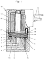
- a multi-way valve according to the invention is exemplary shown as a 3/2-way solenoid valve.
- valve housing 1 with a valve chamber 10 in which a first and a second valve seat 2, 3 is trained. It is also an actuator 4 provided that a first and a second, each with one of the two valve seats 2, 3 cooperating Has closing body 5, 6 and so pivotable is stored in a first switching position (Fig.2) the first closing body 5 with the first valve seat 2 and in the second switching position (Fig.4) second closing body 6 with the second valve seat 3 in Contact comes.
- the two closing bodies 5, 6 are of this type trained that they are on their respective valve seats 2, 3 ensure adequate sealing.
- the valve housing 1 also has a vent connection 7, a pressure port 8 and a working port 9 on, the vent port 7 on the second Valve seat 3 and the pressure connection 8 on the first valve seat 2 opens into the valve chamber 10.
- the two Valve seats 2, 3 are in the region of a bottom 10a Valve chamber 10 arranged. It also flows into this floor also the work connection 9.
- the illustrated Multi-way valve thus optionally provides the connection between vent port 7 and working port 9 or pressure port 8 and working port 9 ago.
- the actuating element 4 is bar-shaped and is supported on the bottom 10a of the valve chamber 10 at least one of two approaches 4a, 4b.
- the two Closing bodies 5, 6 are each at an end region on the side of the actuating element facing the floor 10a appropriate.
- the actuator 4 is slightly curved or kinked so that in two switch positions, the one closing body sits tightly on the associated valve seat and the each other closing body with sufficient stroke is lifted off its valve seat.
- the control of the pivoting process of the actuating element is by an actuator cooperating with this causes.
- the actuator becomes exemplary formed by an electromagnet 11 which is essentially from a magnetic coil 12, a yoke 13 and there is a hinged anchor 14.
- the excitation of the electromagnet 11 takes place via connections 15, the hinged anchor 14 then from its folded-down position in FIG against the force of a spring element 16 to the Electromagnet 11 is folded.
- the folding anchor 14 is therefore for performing the folding movement at its end remote from the spring element 16 supported in a suitable manner pivotable.
- the hinged anchor 14 stands in the region of its free end on its side facing away from the electromagnet 11 the actuator 4 in contact. Without suggestion from the The hinged armature 14 is electromagnet 11 by the spring element 16 folded down, the hinged anchor 14 over the actuator 4 the closing body 5 on his Valve seat 2 presses.
- the panning process is again based on the Fig. 2 to 4 explained in more detail.
- the position of the actuating element 4 according to Figure 2 corresponds the position shown in Figure 1, in which the electromagnet 11 is de-energized. 3 shows an intermediate position, where the folding anchor is already partially folded is. Both are in this intermediate position Closing body 5, 6 lifted from their valve seats 2, 3. Finally, in Figure 4 is the second switching position shown, in which the hinged armature 14 on the electromagnet 11 is folded.
- the actuating element 4 acts as during the pivoting process double-sided lever, which has two pivot axes, between the means of generating a on the Actuating element 4 acting force component arranged and are supported by the two on the floor 10a Lugs 4a, 4b of the actuating element 4 are formed will.
- the bottom 10a in the area of the lugs 4a, 4b of the actuating element correspondingly complementary to the approaches trained to the actuator 4 a unique Assign location within the valve chamber 10.
- the approach 4b is first effective as a pivot axis. This results (according to FIG. 4) between the spring element 17 and the pivot axis 4b, a lever arm l 1b , which is larger than the lever arm l 2b formed between the pivot axis 4b and the first closing body 5.
- the spring element 16 must therefore not only the pending Pressure in the area of the second valve seat, but also overcome the force of the further spring element 17.
- the Accordingly, spring element 16 must have a larger force component produce. Act during this swiveling process supporting the two pivot axes of the actuating element 4.
- the spring element can provide favorable leverage 16 can be designed smaller.
- the electromagnet 11 only needs to be interpreted to the extent that it is Folding anchor 14 against the force of the spring element 16 can fold.
- a spring element 16 with less spring force thus also enables an electromagnet with correspondingly reduced performance.
Applications Claiming Priority (2)
| Application Number | Priority Date | Filing Date | Title |
|---|---|---|---|
| DE19718408 | 1997-04-30 | ||
| DE19718408A DE19718408A1 (de) | 1997-04-30 | 1997-04-30 | Mehrwegeventil |
Publications (3)
| Publication Number | Publication Date |
|---|---|
| EP0875701A2 true EP0875701A2 (fr) | 1998-11-04 |
| EP0875701A3 EP0875701A3 (fr) | 1999-08-11 |
| EP0875701B1 EP0875701B1 (fr) | 2002-06-12 |
Family
ID=7828311
Family Applications (1)
| Application Number | Title | Priority Date | Filing Date |
|---|---|---|---|
| EP98103637A Expired - Lifetime EP0875701B1 (fr) | 1997-04-30 | 1998-03-02 | Soupape à plusieurs voies |
Country Status (4)
| Country | Link |
|---|---|
| US (1) | US5983941A (fr) |
| EP (1) | EP0875701B1 (fr) |
| JP (1) | JPH10311444A (fr) |
| DE (2) | DE19718408A1 (fr) |
Cited By (5)
| Publication number | Priority date | Publication date | Assignee | Title |
|---|---|---|---|---|
| EP1158182A1 (fr) * | 2000-05-25 | 2001-11-28 | FESTO AG & Co | Agencement de soupape |
| DE10239719A1 (de) * | 2002-02-27 | 2003-09-04 | Wilo Ag | Ventil mit Klappe |
| EP1045150A3 (fr) * | 1999-04-14 | 2003-10-15 | Smc Kabushiki Kaisha | Distributeur à voies multiples |
| CN103062475A (zh) * | 2011-10-21 | 2013-04-24 | 绍兴县娄氏机械制造有限公司 | 一种低功耗节能电磁阀 |
| EP3382211A1 (fr) * | 2017-03-30 | 2018-10-03 | Samson Aktiengesellschaft | Dispositif formant soupape pneumatique |
Families Citing this family (22)
| Publication number | Priority date | Publication date | Assignee | Title |
|---|---|---|---|---|
| US6164621A (en) * | 1999-07-09 | 2000-12-26 | Deka Products Limited Partnership | Simplified piezoelectric valve |
| DE19949361A1 (de) * | 1999-10-13 | 2001-04-19 | Nass Magnet Gmbh | Ventil mit Handbetätigung |
| DE20100471U1 (de) | 2001-01-11 | 2001-03-15 | Buerkert Werke Gmbh & Co | Mikroventil |
| DE50202482D1 (de) | 2002-06-11 | 2005-04-21 | Festo Ag & Co | Magnetventil |
| DE10311238A1 (de) * | 2003-03-14 | 2004-10-07 | Festo Ag & Co. | Verfahren zur Herstellung eines Ventils |
| US7070162B2 (en) * | 2003-07-18 | 2006-07-04 | South Bend Controls, Inc. | Valve actuating apparatus |
| US6974117B2 (en) * | 2003-08-27 | 2005-12-13 | South Bend Controls, Inc. | Proportional valve actuating apparatus |
| CN101101069B (zh) * | 2006-07-04 | 2010-12-22 | 深圳迈瑞生物医疗电子股份有限公司 | 微型阀 |
| DE102007004377A1 (de) * | 2007-01-29 | 2008-08-07 | Diener Precision Pumps Ltd. | Elektromagnetisch zu betätigendes Ventil |
| US8430378B2 (en) * | 2008-05-30 | 2013-04-30 | South Bend Controls Holdings Llc | High flow proportional valve |
| DE102008039420B4 (de) * | 2008-08-13 | 2011-04-28 | Prettl, Rolf | Fluidwegeventil |
| US20100314568A1 (en) * | 2009-06-15 | 2010-12-16 | South Bend Controls, Inc. | Solenoid coil |
| DE102009058164A1 (de) * | 2009-12-15 | 2011-06-16 | Svm Schultz Verwaltungs-Gmbh & Co. Kg | Ventil mit einem Betätigungsglied |
| US20120199768A1 (en) * | 2011-02-03 | 2012-08-09 | Love Lonnie J | Mesofluidic digital valve |
| DE202011003472U1 (de) | 2011-03-03 | 2011-05-05 | Bürkert Werke GmbH | Magnetventil |
| CN102102772B (zh) * | 2011-03-11 | 2013-04-24 | 广东新宝电器股份有限公司 | 流道转换阀及采用该阀的电熨斗 |
| DE202013003049U1 (de) * | 2013-04-03 | 2013-05-06 | Bürkert Werke GmbH | Magnetventil, Batterie aus Magnetventilen sowie Werkzeug |
| JP6228439B2 (ja) * | 2013-11-26 | 2017-11-08 | 住友ゴム工業株式会社 | 弁装置 |
| JP6228450B2 (ja) * | 2013-12-24 | 2017-11-08 | 住友ゴム工業株式会社 | 弁装置 |
| JP6190340B2 (ja) * | 2014-08-27 | 2017-08-30 | 株式会社コガネイ | 電磁弁 |
| EP3572698A1 (fr) * | 2018-05-21 | 2019-11-27 | Fas Medic S.A. | Soupape culbutée comportant un mécanisme de soupape culbutée |
| KR20230048548A (ko) * | 2020-08-19 | 2023-04-11 | 민콘 인터내셔널 리미티드 | 충격 드릴 공구용 플래퍼 밸브 |
Citations (1)
| Publication number | Priority date | Publication date | Assignee | Title |
|---|---|---|---|---|
| DE4405657A1 (de) | 1994-02-22 | 1995-08-24 | Buerkert Werke Gmbh & Co | Magnetventil |
Family Cites Families (10)
| Publication number | Priority date | Publication date | Assignee | Title |
|---|---|---|---|---|
| US2825360A (en) * | 1953-03-20 | 1958-03-04 | Samson Appbau Akt Ges | Tilting nozzle relay |
| DE7324333U (de) * | 1973-06-30 | 1973-09-27 | Honeywell Gmbh | Magnetventil |
| US3960361A (en) * | 1975-03-14 | 1976-06-01 | Bertea Corporation | Solenoid valve |
| US3991788A (en) * | 1975-08-28 | 1976-11-16 | Coffee-Mat Corporation | Fluid flow distributor for multi-choice vending machine |
| US4474212A (en) * | 1981-05-11 | 1984-10-02 | Harper-Wyman Company | Proportional flow control valve |
| JPS5945376U (ja) * | 1982-09-17 | 1984-03-26 | アイシン精機株式会社 | 調圧バルブ装置 |
| DE3342951C2 (de) * | 1983-11-26 | 1986-12-18 | Daimler-Benz Ag, 7000 Stuttgart | Betätigungseinrichtung für zwei abhängig voneinander betätigbare Ventile |
| DE3739048C2 (de) * | 1987-11-17 | 2001-08-09 | Buerkert Gmbh | Mehrwegeventil |
| DE4432588C2 (de) * | 1994-09-13 | 2003-10-30 | Buerkert Werke Gmbh & Co | Bistabiles Magnetventil |
| DE29501157U1 (de) * | 1995-01-25 | 1995-03-09 | Buerkert Werke Gmbh & Co | Kleinventil |
-
1997
- 1997-04-30 DE DE19718408A patent/DE19718408A1/de not_active Withdrawn
-
1998
- 1998-03-02 EP EP98103637A patent/EP0875701B1/fr not_active Expired - Lifetime
- 1998-03-02 DE DE59804392T patent/DE59804392D1/de not_active Expired - Fee Related
- 1998-03-19 US US09/044,290 patent/US5983941A/en not_active Expired - Fee Related
- 1998-04-27 JP JP10117152A patent/JPH10311444A/ja not_active Withdrawn
Patent Citations (1)
| Publication number | Priority date | Publication date | Assignee | Title |
|---|---|---|---|---|
| DE4405657A1 (de) | 1994-02-22 | 1995-08-24 | Buerkert Werke Gmbh & Co | Magnetventil |
Cited By (6)
| Publication number | Priority date | Publication date | Assignee | Title |
|---|---|---|---|---|
| EP1045150A3 (fr) * | 1999-04-14 | 2003-10-15 | Smc Kabushiki Kaisha | Distributeur à voies multiples |
| EP1158182A1 (fr) * | 2000-05-25 | 2001-11-28 | FESTO AG & Co | Agencement de soupape |
| US6499509B2 (en) | 2000-05-25 | 2002-12-31 | Festo Ag & Co. | Valve means |
| DE10239719A1 (de) * | 2002-02-27 | 2003-09-04 | Wilo Ag | Ventil mit Klappe |
| CN103062475A (zh) * | 2011-10-21 | 2013-04-24 | 绍兴县娄氏机械制造有限公司 | 一种低功耗节能电磁阀 |
| EP3382211A1 (fr) * | 2017-03-30 | 2018-10-03 | Samson Aktiengesellschaft | Dispositif formant soupape pneumatique |
Also Published As
| Publication number | Publication date |
|---|---|
| EP0875701B1 (fr) | 2002-06-12 |
| US5983941A (en) | 1999-11-16 |
| EP0875701A3 (fr) | 1999-08-11 |
| DE59804392D1 (de) | 2002-07-18 |
| DE19718408A1 (de) | 1998-11-05 |
| JPH10311444A (ja) | 1998-11-24 |
Similar Documents
| Publication | Publication Date | Title |
|---|---|---|
| EP0875701B1 (fr) | Soupape à plusieurs voies | |
| EP0578168B1 (fr) | Valve | |
| DE3519203A1 (de) | Stellvorrichtung fuer eine tuer eines kraftfahrzeugs | |
| DE2417835C3 (de) | Steuerventileinrichtung für eine druckmittelbetriebene Stellvorrichtung in Sicherheitsschaltung | |
| DE4308679A1 (fr) | ||
| EP1084358A1 (fr) | Double vanne de securite | |
| DE3917064A1 (de) | Stossdaempfer ii | |
| DE3346290A1 (de) | Magnetventil | |
| DE3722315C2 (fr) | ||
| DE2553250A1 (de) | Membranbetaetigtes mehrwegeventil | |
| DE602004005533T2 (de) | Elektropneumatischer Luftdruckregler | |
| EP1353103A2 (fr) | Dispositif de soupape avec commande électromagnétique | |
| EP0074420A1 (fr) | Clapet proportionnel électro-hydraulique | |
| EP3359852B1 (fr) | Électrovanne pneumatique | |
| AT412366B (de) | Ventil | |
| EP1001199A2 (fr) | Dispositif de soupape double | |
| DE3342951C2 (de) | Betätigungseinrichtung für zwei abhängig voneinander betätigbare Ventile | |
| DE2501844A1 (de) | Solenoidventil | |
| EP1322880A2 (fr) | Systeme de soupapes a commande electromagnetique et dispositif a soupapes | |
| EP1564466A1 (fr) | Soupape à siège double dans une configuration à voies multiples avec commande magnétique | |
| DE19834786C2 (de) | Elektromagnetisches Wegesitzventil | |
| DE3811669A1 (de) | Ventil | |
| EP1552117B1 (fr) | Dispositif electromagnetique d'actionnement de soupape a position neutre reglable | |
| DE7412924U (de) | Sicherheitsventil | |
| CH646544A5 (de) | Verfahren und einrichtung zur anpassung der wirkung eines elektromagneten an eine vom elektromagneten zu betaetigende komponente. |
Legal Events
| Date | Code | Title | Description |
|---|---|---|---|
| PUAI | Public reference made under article 153(3) epc to a published international application that has entered the european phase |
Free format text: ORIGINAL CODE: 0009012 |
|
| AK | Designated contracting states |
Kind code of ref document: A2 Designated state(s): CH DE FR GB IT LI |
|
| AX | Request for extension of the european patent |
Free format text: AL;LT;LV;MK;RO;SI |
|
| PUAL | Search report despatched |
Free format text: ORIGINAL CODE: 0009013 |
|
| RIC1 | Information provided on ipc code assigned before grant |
Free format text: 6F 16K 31/06 A |
|
| AK | Designated contracting states |
Kind code of ref document: A3 Designated state(s): AT BE CH DE DK ES FI FR GB GR IE IT LI LU MC NL PT SE |
|
| AX | Request for extension of the european patent |
Free format text: AL;LT;LV;MK;RO;SI |
|
| 17P | Request for examination filed |
Effective date: 20000121 |
|
| AKX | Designation fees paid |
Free format text: CH DE FR GB IT LI |
|
| GRAG | Despatch of communication of intention to grant |
Free format text: ORIGINAL CODE: EPIDOS AGRA |
|
| GRAG | Despatch of communication of intention to grant |
Free format text: ORIGINAL CODE: EPIDOS AGRA |
|
| GRAH | Despatch of communication of intention to grant a patent |
Free format text: ORIGINAL CODE: EPIDOS IGRA |
|
| 17Q | First examination report despatched |
Effective date: 20011010 |
|
| GRAH | Despatch of communication of intention to grant a patent |
Free format text: ORIGINAL CODE: EPIDOS IGRA |
|
| GRAA | (expected) grant |
Free format text: ORIGINAL CODE: 0009210 |
|
| AK | Designated contracting states |
Kind code of ref document: B1 Designated state(s): CH DE FR GB IT LI |
|
| REG | Reference to a national code |
Ref country code: GB Ref legal event code: FG4D Free format text: NOT ENGLISH |
|
| REG | Reference to a national code |
Ref country code: CH Ref legal event code: NV Representative=s name: RIEDERER HASLER & PARTNER PATENTANWAELTE AG Ref country code: CH Ref legal event code: EP |
|
| REF | Corresponds to: |
Ref document number: 59804392 Country of ref document: DE Date of ref document: 20020718 |
|
| ET | Fr: translation filed | ||
| PLBE | No opposition filed within time limit |
Free format text: ORIGINAL CODE: 0009261 |
|
| STAA | Information on the status of an ep patent application or granted ep patent |
Free format text: STATUS: NO OPPOSITION FILED WITHIN TIME LIMIT |
|
| 26N | No opposition filed |
Effective date: 20030313 |
|
| PGFP | Annual fee paid to national office [announced via postgrant information from national office to epo] |
Ref country code: FR Payment date: 20040209 Year of fee payment: 7 |
|
| PGFP | Annual fee paid to national office [announced via postgrant information from national office to epo] |
Ref country code: GB Payment date: 20040212 Year of fee payment: 7 |
|
| PGFP | Annual fee paid to national office [announced via postgrant information from national office to epo] |
Ref country code: CH Payment date: 20040213 Year of fee payment: 7 |
|
| PGFP | Annual fee paid to national office [announced via postgrant information from national office to epo] |
Ref country code: DE Payment date: 20040512 Year of fee payment: 7 |
|
| PG25 | Lapsed in a contracting state [announced via postgrant information from national office to epo] |
Ref country code: IT Free format text: LAPSE BECAUSE OF NON-PAYMENT OF DUE FEES Effective date: 20050302 Ref country code: GB Free format text: LAPSE BECAUSE OF NON-PAYMENT OF DUE FEES Effective date: 20050302 |
|
| PG25 | Lapsed in a contracting state [announced via postgrant information from national office to epo] |
Ref country code: LI Free format text: LAPSE BECAUSE OF NON-PAYMENT OF DUE FEES Effective date: 20050331 Ref country code: CH Free format text: LAPSE BECAUSE OF NON-PAYMENT OF DUE FEES Effective date: 20050331 |
|
| PG25 | Lapsed in a contracting state [announced via postgrant information from national office to epo] |
Ref country code: DE Free format text: LAPSE BECAUSE OF NON-PAYMENT OF DUE FEES Effective date: 20051001 |
|
| REG | Reference to a national code |
Ref country code: CH Ref legal event code: PL |
|
| GBPC | Gb: european patent ceased through non-payment of renewal fee |
Effective date: 20050302 |
|
| PG25 | Lapsed in a contracting state [announced via postgrant information from national office to epo] |
Ref country code: FR Free format text: LAPSE BECAUSE OF NON-PAYMENT OF DUE FEES Effective date: 20051130 |
|
| REG | Reference to a national code |
Ref country code: FR Ref legal event code: ST Effective date: 20051130 |