EP0875651A2 - Automatic adjusting device - Google Patents
Automatic adjusting device Download PDFInfo
- Publication number
- EP0875651A2 EP0875651A2 EP98102033A EP98102033A EP0875651A2 EP 0875651 A2 EP0875651 A2 EP 0875651A2 EP 98102033 A EP98102033 A EP 98102033A EP 98102033 A EP98102033 A EP 98102033A EP 0875651 A2 EP0875651 A2 EP 0875651A2
- Authority
- EP
- European Patent Office
- Prior art keywords
- hinge
- frame
- wing
- locking elements
- another
- Prior art date
- Legal status (The legal status is an assumption and is not a legal conclusion. Google has not performed a legal analysis and makes no representation as to the accuracy of the status listed.)
- Granted
Links
- 238000004146 energy storage Methods 0.000 claims description 5
- 230000008878 coupling Effects 0.000 description 8
- 238000010168 coupling process Methods 0.000 description 8
- 238000005859 coupling reaction Methods 0.000 description 8
- 235000001674 Agaricus brunnescens Nutrition 0.000 description 5
- 210000003128 head Anatomy 0.000 description 5
- 230000000694 effects Effects 0.000 description 3
- 210000002105 tongue Anatomy 0.000 description 2
- 229910000639 Spring steel Inorganic materials 0.000 description 1
- 230000002411 adverse Effects 0.000 description 1
- 230000001174 ascending effect Effects 0.000 description 1
- 230000000903 blocking effect Effects 0.000 description 1
- 230000000295 complement effect Effects 0.000 description 1
- 238000006073 displacement reaction Methods 0.000 description 1
- 238000005516 engineering process Methods 0.000 description 1
- 210000003746 feather Anatomy 0.000 description 1
- 238000007654 immersion Methods 0.000 description 1
- 230000003993 interaction Effects 0.000 description 1
- 238000004519 manufacturing process Methods 0.000 description 1
- 239000002184 metal Substances 0.000 description 1
- 238000000465 moulding Methods 0.000 description 1
- 230000003287 optical effect Effects 0.000 description 1
- 230000035515 penetration Effects 0.000 description 1
- 230000002035 prolonged effect Effects 0.000 description 1
- 230000000717 retained effect Effects 0.000 description 1
Images

Classifications
-
- E—FIXED CONSTRUCTIONS
- E05—LOCKS; KEYS; WINDOW OR DOOR FITTINGS; SAFES
- E05F—DEVICES FOR MOVING WINGS INTO OPEN OR CLOSED POSITION; CHECKS FOR WINGS; WING FITTINGS NOT OTHERWISE PROVIDED FOR, CONCERNED WITH THE FUNCTIONING OF THE WING
- E05F7/00—Accessories for wings not provided for in other groups of this subclass
- E05F7/005—Aligning devices for wings
-
- E—FIXED CONSTRUCTIONS
- E05—LOCKS; KEYS; WINDOW OR DOOR FITTINGS; SAFES
- E05D—HINGES OR SUSPENSION DEVICES FOR DOORS, WINDOWS OR WINGS
- E05D15/00—Suspension arrangements for wings
- E05D15/48—Suspension arrangements for wings allowing alternative movements
- E05D15/52—Suspension arrangements for wings allowing alternative movements for opening about a vertical as well as a horizontal axis
- E05D15/5205—Suspension arrangements for wings allowing alternative movements for opening about a vertical as well as a horizontal axis with horizontally-extending checks
-
- E—FIXED CONSTRUCTIONS
- E05—LOCKS; KEYS; WINDOW OR DOOR FITTINGS; SAFES
- E05F—DEVICES FOR MOVING WINGS INTO OPEN OR CLOSED POSITION; CHECKS FOR WINGS; WING FITTINGS NOT OTHERWISE PROVIDED FOR, CONCERNED WITH THE FUNCTIONING OF THE WING
- E05F7/00—Accessories for wings not provided for in other groups of this subclass
- E05F7/06—Devices for taking the weight of the wing, arranged away from the hinge axis
-
- E—FIXED CONSTRUCTIONS
- E05—LOCKS; KEYS; WINDOW OR DOOR FITTINGS; SAFES
- E05Y—INDEXING SCHEME ASSOCIATED WITH SUBCLASSES E05D AND E05F, RELATING TO CONSTRUCTION ELEMENTS, ELECTRIC CONTROL, POWER SUPPLY, POWER SIGNAL OR TRANSMISSION, USER INTERFACES, MOUNTING OR COUPLING, DETAILS, ACCESSORIES, AUXILIARY OPERATIONS NOT OTHERWISE PROVIDED FOR, APPLICATION THEREOF
- E05Y2800/00—Details, accessories and auxiliary operations not otherwise provided for
- E05Y2800/37—Length, width or depth adjustment
-
- E—FIXED CONSTRUCTIONS
- E05—LOCKS; KEYS; WINDOW OR DOOR FITTINGS; SAFES
- E05Y—INDEXING SCHEME ASSOCIATED WITH SUBCLASSES E05D AND E05F, RELATING TO CONSTRUCTION ELEMENTS, ELECTRIC CONTROL, POWER SUPPLY, POWER SIGNAL OR TRANSMISSION, USER INTERFACES, MOUNTING OR COUPLING, DETAILS, ACCESSORIES, AUXILIARY OPERATIONS NOT OTHERWISE PROVIDED FOR, APPLICATION THEREOF
- E05Y2900/00—Application of doors, windows, wings or fittings thereof
- E05Y2900/10—Application of doors, windows, wings or fittings thereof for buildings or parts thereof
- E05Y2900/13—Type of wing
- E05Y2900/132—Doors
-
- E—FIXED CONSTRUCTIONS
- E05—LOCKS; KEYS; WINDOW OR DOOR FITTINGS; SAFES
- E05Y—INDEXING SCHEME ASSOCIATED WITH SUBCLASSES E05D AND E05F, RELATING TO CONSTRUCTION ELEMENTS, ELECTRIC CONTROL, POWER SUPPLY, POWER SIGNAL OR TRANSMISSION, USER INTERFACES, MOUNTING OR COUPLING, DETAILS, ACCESSORIES, AUXILIARY OPERATIONS NOT OTHERWISE PROVIDED FOR, APPLICATION THEREOF
- E05Y2900/00—Application of doors, windows, wings or fittings thereof
- E05Y2900/10—Application of doors, windows, wings or fittings thereof for buildings or parts thereof
- E05Y2900/13—Type of wing
- E05Y2900/148—Windows
Definitions
- the invention relates to a device for aligning the Wing of a door, a window or the like. Relative to one fixed frame, with sash and frame over a relative to the frame adjustable axis of rotation through Hinge elements are formed at least around a vertical one Rotational axis are pivotally connected to each other that the Hinge made of at least two movable relative to each other Hinge parts exist, with a first part stationary in the Frame and a second positionally assigned to the wing with one at least in the surface-parallel position of sash and frame acting alignment element producing an alignment movement.
- the frame can be turned by turning the adjusting screw be caused, which is a relative displacement of the end of the Hinge arm attached coupling piece with respect to the Hinge arm results.
- the adjustment is done manually and may have to be in be repeated at regular intervals as the wing follows some time by loosening the fasteners and by Wear of the bearing components an anti-parallel position to the frame occupies.
- Sashes and frames can also have auxiliary devices are aligned with each other, such as the DE 327 608 or also show DE 41 17 407 C2.
- auxiliary devices are aligned with each other, such as the DE 327 608 or also show DE 41 17 407 C2.
- Another device for aligning the wing opposite the framework is known from DE-OS 20 65 840.
- a downward protruding coupling piece attached which with a Bolt linkage of the wing attached locking bolt cooperates, with the dome as the mushroom head pin trained locking pin engages around a fork.
- the coupling piece is anti-parallel to the rebate circumferential surface of the wing or the frame aligned and causes at one Movements of the locking pin a relative movement of the Wing opposite the frame.
- the object of the invention is therefore a device for Align the wing of a door, a window or the like. in relation to a fixed frame, that this independently by normal operation of the wing takes place with a safe storage of the sash on the frame and lock against the alignment movement.
- the object is achieved by one or more between the hinge parts acting automatically acting locking element or locking elements, which fix the hinge parts against each other, the Hinge parts against each other by the alignment element are movable.
- Locking elements look like Form-fit elements exist, and that the form-fit elements between them by aligning each other removing boundary edges of the hinge parts relocatable are arranged.
- a simple design and manufacturing technology Design provides that the positive locking elements from with Wedge-provided actuators exist, the Wedge surfaces lie against each other and the adjusting pieces against each other are arranged displaceable.
- Another embodiment is to prevent large wings the invention that the wedge surfaces offset from step-like lying, to an opposite to the alignment movement load direction, almost vertical aligned plan areas exist, with the steps through Sections running at an obtuse angle to the plane surfaces are connected.
- This configuration causes the on Normal forces due to the vertical Flat surfaces are transferred while making an adjustment the wedge surfaces interacting with each other adjusting the Effect form-locking elements.
- a particularly simple embodiment provides that one of the Wedge surfaces in one piece with a fixed to the axis of rotation connected hinge frame is formed. This reduces the necessary assembly work considerably.
- Form-fit elements consist of plate-shaped components and the boundary edges are almost perpendicular to Direction of loading.
- the invention further provides that the positive locking elements through an energy storage device into which the hinge parts mutually blocking position are brought. This is supposed to Possibly friction or acting between the interlocking elements. Like. Be overcome.
- a preferred embodiment also provides that one of the hinge parts is designed as a hinge arm, the one with a hinge pin forming the hinge axis fixed and at the other end with the wing-fixed hinge part - Angled part is connected at least lengthways.
- This Design relates above all to turn and tilt and turn sash commercially available fittings, which subsequently with automatic effective adjustment should be equipped.
- one of the Hinge parts is designed as a frame-fixed bearing block, while the second moved by means of the alignment element Hinge part is formed by the bearing pin and when the Positive locking elements via a force accumulator, in particular via a spring are connected.
- the bearing pin enclosing bearing eyes transverse to the axis of rotation - in the Frame level - are elongated and that the Interlocking elements between the narrow side walls of the Bearing eyes and the bearing pin are arranged.
- the Narrow side walls and the positive locking elements with adjacent wedge surfaces are provided.
- a right and such a bearing block can be used on the left, if the two bearing eyes are symmetrical on a base plate are arranged. In this case, the bearing block can be used for both can be used on the right and for windows that can be opened on the left.
- a particularly simple embodiment of such Bearing block provides that the energy storage device as Tension spring is formed. This can be between the two Form-fit elements are and be effective between them.
- the locking device from a locking device locking against the opening device consists. This also works positively, but prevents it sliding the hinge parts back into position Alignment movement.
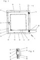
- FIG. 1 shows a window 1 consisting of a fixed frame 2 and one in it both about a vertical axis of rotation 3 and wings 4 pivotable about a horizontal axis of rotation 5 Frame 2 and the wing 5 are via an upper hinge 6 and a lower hinge 7 connected to each other.
- the design provides that the upper hinge 6th is designed as a so-called scissor stay, while the lower hinge 7 is designed as a so-called corner bearing.
- the Wing 5 has one for locking in the frame 2 - here not shown - locking fitting on a Hand lever 8 on wing 5 can be operated.
- the locking fitting is made of a turn-tilt fitting via the hand lever 8 also the possibility for one Swiveling movement around the lower horizontal axis of rotation 4 adjustable.
- On the upper horizontal wing spar 9 is in this case, an opening device with a perpendicular to Wing-level movable extension arm attached to the upper horizontal wing spar 9 connects to the upper hinge 6.
- At the lower horizontal wing spar 10 is between the frame 2 and wing 5 a - not visible here - tilt lock effective so that the lower horizontal wing edge 11 on the frame 2 is held.
- the Frame spars of the frame 2 and the wing spars of the wing 5 do not run in parallel, but through prolonged use, Wear or the like. Moved to an antiparallel position to have. This is a between the wing 5 and the frame 2nd in the - indicated - starting position 12 existing distance of Folded surfaces 13, 14 - the so-called folded air or the chamber dimension 15 - reduced to a minimum in individual areas. Therefore it comes when closing the wing 5, for example, from the Rotary position for clamping.
- an alignment element 17 is provided which is in contact with the fold surface 14 of wing 5 or one - not shown here - fixed component interacts in such a way that the original intended distance of the folding surfaces 14, 13 at Closing of the wing 5 again.
- the alignment element In the simplest case, 17 consists of one with an in Equipped with ascending ramp Casserole, which with the fold surface 14 of the wing cooperates.
- the wing 5 receives through the alignment element 17th its original starting position 12, in which the frame and Wing spars are parallel to each other. When opening the wing 5 however the front wing edge 18 sinks down again, as soon as the fold surface 14 slips off the alignment element 17.
- the wing 5 can only by manually lifting the front wing edge 18 into the frame 2 immerse yourself.
- Tilt and turn fittings therefore provide that on the upper hinge 6 manual adjustment options are attached to the Restore the starting position 12 serve.
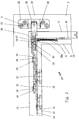
- Fig. 2 shows an upper hinge assembly 20, which consists of a wing-fixed angle component 21, one movable transversely thereto mounted hinge arm 22, one attached to the end and in front of the frame plane projecting coupling part 23 and a fixed to the frame, fixed on the frame visible surface 24 Bearing block 25, the bearing block 25 and that Coupling part 23 pivotally connected via a journal 26 are.
- one Hinge arrangement 20 is a pure one Rotary fitting, in which only one vertical axis of rotation 3 is provided is.
- the angle component 21 is fastened in here a fitting groove 27 introduced into the rebate surface 14 Hinge arm 22 is on the pin 28, 29 with the Angular component 21 connected, the pin 29 fixed in the Angle component 21 is anchored and the hinge arm 22 in one Passes through slot 30 and this with a mushroom head 31st backs up.
- the pin 28 is rotatable eccentrically in the Angle component 21 is mounted and extends through the angle component 21 in an elongated hole 32 and also has a mushroom head 33.
- the eccentric mounting of the pin 28 is used for Achieving a larger pressure of the wing 5 on the frame 2, i.e.
- the oblong hole 30 almost corresponds in its transverse dimension the diameter of the pin 29 so that the hinge arm 22 at Actuation of the pin 28 by an inserted therein Tool engagement 34 around the pin 29 acting as the axis of rotation is pivoted, whereby the wing plane is opposite the Frame level shifted.
- the hinge arrangement 20 in the illustrated embodiment also has a manually operated adjusting screw 35 on, which acts in the longitudinal direction of the hinge arm 22. This is with a - not visible - thread at the end of a Actuator 36 in engagement, but on the other hand by their location on the coupling part 23 and over the bearing pin 26 with stationary connected to the frame 2.
- Window 1 also shows - not here visible - alignment element 17, which the wing 5 in the closed position - i.e. when immersing the wing 5 in align the frame 2 - in a parallel position.
- the angle member 21 is relative to Hinge arm 22 moves until the fold surfaces 13, 14th stand parallel and the rebate clearance or the chamber dimension 15 in its normal size.
- the hinge arm 22 which, because it is stationary the bearing pin 26 is connected to the frame-fixed bearing block 25, the alignment movement is not carried out.
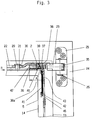
- the form-locking element 37 passes through the common Recess 38 of the hinge arm 22 and the actuator 36 and a recess 38a in the angle component 21.
- the almost vertical back of the form-locking element 37 lies at least in the area of the recess 38a of the Angular component 21 in a form-fitting manner on this.
- the positive locking element 37 becomes free to an extent that corresponds to the amount in the front - not visible here Wing edge 18 is raised.
- the tension spring 41 that Form-locking element 37 pulled down so that - according to the wedge effect - the new, spread position of the Hinge arm 22 adjusts with respect to the angle component 21.
- Locking element acting form-locking element 37 against the Direction R loaded where it is form-fitting between the Angle component 21 and the hinge arm 22 and this to each other, against the direction R of the alignment movement, in Load direction fixed, i.e. locked. In the R direction the lock can still be released.
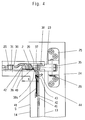
- FIG. 4 shows the hinge arrangement 20 corresponding to FIG. 3, where the automatic alignment has already taken effect. How is particularly visible in connection with Fig. 3, by the immersion of the positive locking element 37, the relative position of the Hinge arm 22 changed with respect to the angular component 21, see above that the distance between two arbitrarily chosen points on each Component - here based on the fold surface 14 and the Boundary edge 42 'of the actuator 36 shown - changes.
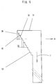
- the positive locking element 37 can - as shown in FIG. 5 - also by a plug 45, which is seated in the opening 43, fixed will. This is for example when installing the Hinge arrangement 20 makes sense to the adjustment range of automatic adjustment.
- the plug 45 protrudes through the leg 46 of the angle component 21 and touches with its lateral surface 47 the lower end 48 of the Form-locking element 37 in its initial position.
- the plug 45 According to this configuration, it is only after the wing 5 has been installed removed from the opening 43 on the frame 2, so that the Form-locking element 37 only then becomes movable.
- Fig. 6 shows the form-locking element 37 in an enlarged Scale.
- the form-locking element 37 has a wedge shape the step-shaped shoulders 50 are arranged.
- the depth 52 of paragraphs 50 determines the minimum possible measure with which the alignment movement of the alignment element 17 can be fixed can. The smaller this depth 52 is chosen, the finer Alignment movements can be fixed and retained.
- phase-like sections 53 running to the flat surfaces 51 get connected.
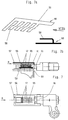
- FIG. 7 shows an embodiment of an opening device a tilt-and-turn window, the as locking elements acting form-locking elements 37 made of plate-shaped components exist in an opening 55 of the actuator 36th lie next to each other in layers.
- the positive locking elements 37 are loaded on their underside by spring elements. Is the actuator 36 slidably leading and overlapping extension arm 56 by the aligning force in Direction R - together with wing 5 - moves, so coincide the opening 57 in the opening arm 56 and the opening 55 in Actuator 36 partially.
- Fig. 7a a Design are selected according to Fig. 7a, in which the spring elements consist of spring tongues 58, which are mutually running parallel and by a common transverse web 59 are connected and the molded part 60 form.
- the molded part 60 can be stamped or the like produce a spring steel and is on the actuator 36 attached.
- the extension arm 56 - also to avoid the Penetration of the mobility of the form-locking elements 37 impairing dirt - with a thin-walled cover 61 closed.
- This thin-walled cover 61 can for example from a removable plastic or sheet metal part be formed.
- FIGS. 8a and 8b show a schematic Embodiment of the invention in which the Form-locking elements 37 in a fixed position on the frame 2 Bearing block 70 are performed.
- a tape roll 71 is in Transverse direction fixed with a - not shown - extension arm an opening device or the like connected. This protrudes a cantilever 72 of the tape roll 71 to before - not here either shown - folded surface 13 of the frame 2.
- the tape roll 71st encompasses a bearing pin 73 which is in an elongated hole Bearing eyes 74 of the bearing block 70 parallel to the frame plane is led.
- the bearing block 70 has bearing eyes 74 in which the positive locking elements 37 along the central axis of the Bearing pin 73 are performed.
- the bearing eyes 74 are on one Provide the end with the wedge surfaces 40 to the central transverse axis 75 of the bearing block 70 the wall thickness of the bearing eye 74 enlarge.
- the form-locking elements 37 are also with Wedge surfaces 39 provided in the opposite direction run so that the bearing pin 73 facing, with a Circular segment 76 provided lateral boundary edges 77 of the Form-locking elements 37 run parallel to the bearing pin 73.
- the illustrated embodiment has compared to the embodiments described above have the advantage that the wing components are left almost unchanged can. Also 15 are attached outside the air gap Do not adapt devices to the limited space available and can be easily od by a suitable cover cap. Adapt to the optical conditions.
- the base plate 79 of the bracket 70 as shown in FIG Recognizing the embodiment is symmetrical with respect to Central transverse axis 75 designed so that the bearing block 70 both for wing 5 opening to the right as well as opening to the left Wing 5 can be used.
- Wings 5 is advantageous if the positive locking element 37 for example according to Fig. 2 to 5 with the vertical back as large as possible on the vertical angle leg 46 des Angle component 21 bears against a tilting or twisting of the Prevent angular component 21.
- angle leg 46 a has an extension projecting into the recess 38 and / or that the interlocking element 37 along the fold surface 14 of the angle leg 46 is guided. This would also do that Moving the form-locking elements 37 relative to the actuator 36 favors.
Landscapes
- Engineering & Computer Science (AREA)
- Mechanical Engineering (AREA)
- Hinges (AREA)
- Fluid-Damping Devices (AREA)
- Massaging Devices (AREA)
- Paper (AREA)
Abstract
Description
Die Erfindung betrifft eine Vorrichtung zum Ausrichten des Flügels einer Tür, eines Fensters od. dgl. relativ zu einem feststehenden Rahmen, wobei Flügel und Rahmen über einen relativ zum Rahmen lagenjustierbare Drehachse die durch Scharnierelemente gebildet wird mindestens um eine vertikale Drehachse schwenkbar miteinander verbunden sind, daß das Scharnier aus mindestens zwei relativ zueinander beweglichen Scharnierteilen besteht, wobei ein erstes Teil ortsfest im Rahmen und ein zweites lagefest dem Flügel zugeordnet ist, mit einem zumindest in flächenparalleler Lage von Flügel und Rahmen wirkenden, eine Ausrichtbewegung erzeugendes Ausrichtelement.The invention relates to a device for aligning the Wing of a door, a window or the like. Relative to one fixed frame, with sash and frame over a relative to the frame adjustable axis of rotation through Hinge elements are formed at least around a vertical one Rotational axis are pivotally connected to each other that the Hinge made of at least two movable relative to each other Hinge parts exist, with a first part stationary in the Frame and a second positionally assigned to the wing with one at least in the surface-parallel position of sash and frame acting alignment element producing an alignment movement.
Es sind Vorrichtungen bekannt, die eine Justage des Flügels bezüglich seiner Lager zum feststehenden Rahmen mittels Stellgliedern erlauben. So ist es beispielsweise aus der DE 36 37 077 C1 ebenso wie einer Reihe weiterer Veröffentlichungen bekannt, einen Scharnierarm bezüglich eines blendrahmenfesten Lagerbocks verschiebbar zu befestigen und entgegen der durch das Gewicht des Flügels wirkenden Belastungsrichtung mittels einer Stellschraube zu sichern.Devices are known for adjusting the wing regarding its bearings to the fixed frame by means of Allow actuators. For example, it is from the DE 36 37 077 C1 as well as a number of others Publications known a hinge arm regarding one frame fixed to the frame and slidable contrary to that acting through the weight of the wing Secure the load direction with an adjusting screw.
Eine Justage des Flügels gegenüber dem feststehenden Blendrahmen kann dabei durch ein Verdrehen der Stellschraube bewirkt werden, was eine Relativverschiebung des am Ende des Scharnierarms angebrachten Kupplungsstücks bezüglich des Scharnierarms zur Folge hat.An adjustment of the wing compared to the fixed The frame can be turned by turning the adjusting screw be caused, which is a relative displacement of the end of the Hinge arm attached coupling piece with respect to the Hinge arm results.
Die Justage erfolgt dabei manuell und muß unter Umständen in regelmäßigen Abständen wiederholt werden, da der Flügel nach einiger Zeit durch Lockerung der Befestigungselemente und durch Verschleiß der Lagerbauteile eine antiparallele Lage zum Rahmen einnimmt.The adjustment is done manually and may have to be in be repeated at regular intervals as the wing follows some time by loosening the fasteners and by Wear of the bearing components an anti-parallel position to the frame occupies.
Flügel und Rahmen können auch über Hilfseinrichtungen
gegeneinander ausgerichtet werden wie sie beispielsweise die
DE 327 608 oder auch die DE 41 17 407 C2 zeigen. Dabei sind
Vorrichtungen zum Ausrichten des Flügels auf der der Drehachse
entgegengesetzt liegenden Seite des Flügels angebracht, die
beim Eintauchen des Flügels in den Rahmen mit lagefest am
Rahmen angebrachten Elemente zusammenwirken und ein Ausrichten
des Flügels bezüglich des Rahmens erzielen.Sashes and frames can also have auxiliary devices
are aligned with each other, such as the
DE 327 608 or also show
Von großem Nachteil ist es dabei, daß derartige Vorrichtungen nur in einem bestimmten Bereich des Schwenkwinkels des Flügels wirken und in dem Wirkbereich, beim Eintauchen des Flügels in dem Blendrahmen, einen Zwang in den Scharnieren bewirken. Weiterhin werden derartige Vorrichtungen bei sehr großen Abweichungen der Lage unwirksam oder müssen durch besondere technisch aufwendige Ausgestaltungen flexibler werden, da sie die ihnen zugeordneten Bauteile an Rahmen nicht treffen bzw. finden und so ein zusammenwirken unmöglich wird. It is a great disadvantage that such devices only in a certain range of the swing angle of the wing act and in the effective range when immersing the wing in the frame, cause a constraint in the hinges. Furthermore, such devices are very large Deviations in the situation ineffective or must be caused by special technically complex designs become more flexible because they the components assigned to them do not meet on the frame or find and such a cooperation becomes impossible.
Auch wird die Kippfunktion bei Dreh-Kipp-Flügeln durch diese Hilfseinrichtungen nachteilig beeinflußt, da die Kipp-Achse durch die Hilfseinrichtung verlagert wird.The tilting function of turn-tilt sashes is also achieved through this Auxiliary devices adversely affected because the tilt axis is shifted by the auxiliary device.
Eine weitere Vorrichtung zum Ausrichten des Flügels gegenüber dem Rahmen ist durch die DE-OS 20 65 840 bekannt geworden. Bei der darin offenbarten Ausstellvorrichtung ist ein nach unten ragendes Kuppelstück angebracht, das mit einem am Riegelgestänge des Flügels befestigten Feststellbolzen zusammenwirkt, wobei das Kuppelstück den als Pilzkopfzapfen ausgebildeten Feststellbolzen gabelförmig umgreift. Das Kuppelstück ist antiparallel zur Falzumfangsfläche des Flügels bzw. des Rahmens ausgerichtet und bewirkt bei einer Verschiebungen des Feststellbolzens eine Relativbewegung des Flügels gegenüber dem Rahmen.Another device for aligning the wing opposite the framework is known from DE-OS 20 65 840. At the display device disclosed therein is a downward protruding coupling piece attached, which with a Bolt linkage of the wing attached locking bolt cooperates, with the dome as the mushroom head pin trained locking pin engages around a fork. The The coupling piece is anti-parallel to the rebate circumferential surface of the wing or the frame aligned and causes at one Movements of the locking pin a relative movement of the Wing opposite the frame.
Es ist dabei von großem Nachteil, daß die Ausrichtung des Flügels nicht in allen Schaltstellungen des Beschlages wirksam ist, sondern - abhängig von der Stellung des Feststellbolzens - die Ausrichtvorrichtung außer Kraft gesetzt wird.It is a major disadvantage that the orientation of the Wing is not effective in all switch positions of the fitting is, but - depending on the position of the locking bolt - the alignment device is overridden.
Aufgabe der Erfindung ist es daher, eine Vorrichtung zum Ausrichten des Flügels einer Tür, eines Fensters od. dgl. relativ zu einem feststehenden Rahmen derart auszugestalten, daß diese selbständig durch normale Betätigung des Flügels erfolgt bei einer sicheren Lagerung des Flügels am Rahmen und entgegen der Ausrichtbewegung sperren.The object of the invention is therefore a device for Align the wing of a door, a window or the like. in relation to a fixed frame, that this independently by normal operation of the wing takes place with a safe storage of the sash on the frame and lock against the alignment movement.
Die Aufgabe wird erfindungsgemäß gelöst durch ein oder mehrere zwischen den Scharnierteilen selbsttätig wirkendes bzw. wirkende Verriegelungselement bzw. Verriegelungselemente, welche die Scharnierteile gegeneinander lagefixieren, wobei die Scharnierteile durch das Ausrichtelement gegeneinander verschiebbar sind. According to the invention, the object is achieved by one or more between the hinge parts acting automatically acting locking element or locking elements, which fix the hinge parts against each other, the Hinge parts against each other by the alignment element are movable.
Eine besonders sichere und einfache Ausgestaltung der Verriegelelemente sieht vor, daß die Verriegelungselemente aus Formschlußelementen bestehen, und daß die Formschlußelemente zwischen sich durch die Ausrichtbewegung voneinander entfernenden Begrenzungskanten der Scharnierteile verlagerbar angeordnet sind.A particularly safe and simple design of the Locking elements provides that the locking elements look like Form-fit elements exist, and that the form-fit elements between them by aligning each other removing boundary edges of the hinge parts relocatable are arranged.
Eine konstruktiv wie herstellungstechnisch einfache Ausgestaltung sieht vor, daß die Formschlußelemente aus mit Keilflächen versehenen Stellstücken bestehen, wobei die Keilflächen aneinander liegen und die Stellstücke gegeneinander verlagerbar angeordnet sind.A simple design and manufacturing technology Design provides that the positive locking elements from with Wedge-provided actuators exist, the Wedge surfaces lie against each other and the adjusting pieces against each other are arranged displaceable.
Dadurch wird erreicht, daß die durch das Ausrichtelement gegeneinander verschobenen Scharnierteile gegeneinander lagenfixiert werden und dadurch die vertikale Drehachse des Flügels relativ zum Flügel verschoben wird. Der Flügel erhält dadurch eine neue Ausrichtung gegenüber dem feststehenden Rahmen und zwar so, daß die aufrechten und waagerechten Holme des Flügels nahezu parallel zu denen des Rahmens stehen. Eine weitere Bedienung des Flügels ist daher problemlos möglich, da die Verriegelungselemente die einmal eingestellte und durch das Ausrichtelement bestimmte Lage des Flügels bezüglich des Rahmens lagenfixieren.This ensures that the alignment element Hinge parts shifted against each other be fixed in position and thereby the vertical axis of rotation of the Wing is moved relative to the wing. The wing receives thereby a new orientation compared to the fixed Frame and in such a way that the upright and horizontal bars of the wing are almost parallel to those of the frame. A further operation of the wing is therefore easily possible, since the locking elements once set and by the Alignment element certain position of the wing with respect to the Fix the frame in place.
Um ein Rückstellen der Verriegelung durch das Flügelgewicht bei großen Flügeln zu verhindern, sieht eine weitere Ausgestaltung der Erfindung vor, daß die Keilflächen aus stufenartig versetzt liegenden, zu einer entgegengesetzt zur Ausrichtbewegung verlaufenden Belastungsrichtung, nahezu senkrecht ausgerichteten Planflächen bestehen, wobei die Stufen durch stumpfwinkelig zu den Planflächen verlaufende Abschnitte verbunden sind. Diese Ausgestaltung bewirkt, daß die auf die Keilflächen wirkenden Normalkräfte durch die senkrechten Planflächen übertragen werden, während bei einer Verstellung die Keilflächen miteinander in Wirkbeziehung ein Verstellen der Formschlußelemente bewirken.To reset the locking by the sash weight Another embodiment is to prevent large wings the invention that the wedge surfaces offset from step-like lying, to an opposite to the alignment movement load direction, almost vertical aligned plan areas exist, with the steps through Sections running at an obtuse angle to the plane surfaces are connected. This configuration causes the on Normal forces due to the vertical Flat surfaces are transferred while making an adjustment the wedge surfaces interacting with each other adjusting the Effect form-locking elements.
Eine besonders einfache Ausgestaltung sieht vor, daß eine der Keilflächen einteilig mit einem fest mit der Drehachse verbundenen Scharnierrahmen ausgebildet ist. Dies reduziert den notwendigen Montageaufwand erheblich.A particularly simple embodiment provides that one of the Wedge surfaces in one piece with a fixed to the axis of rotation connected hinge frame is formed. This reduces the necessary assembly work considerably.
Alternativ kann auch vorgesehen werden, daß die Formschlußelemente aus plattenförmigen Bauteilen bestehen und die Begrenzungskanten nahezu rechtwinklig zur Belastungsrichtung verlaufen.Alternatively, it can also be provided that the Form-fit elements consist of plate-shaped components and the boundary edges are almost perpendicular to Direction of loading.
Die Erfindung sieht weiterhin vor, daß die Formschlußelemente durch eine Kraftspeichervorrichtung in die die Scharnierteile gegeneinander sperrende Lage gebracht werden. Dadurch soll evtl. zwischen den Formschlußelementen wirkende Reibung od. dgl. überwunden werden.The invention further provides that the positive locking elements through an energy storage device into which the hinge parts mutually blocking position are brought. This is supposed to Possibly friction or acting between the interlocking elements. Like. Be overcome.
Eine bevorzugte Ausgestaltung sieht dabei weiterhin vor, daß eines der Scharnierteile als Scharnierarm ausgebildet ist, der einerends mit einem die Scharnierachse bildenden Lagerbolzen fest und anderenends mit dem flügelfesten Scharnierteil - Winkelteil -zumindest längsverschieblich verbunden ist. Diese Ausgestaltung betrifft vor allem Dreh- und Drehkippflügel mit handelsüblichen Beschlägen, die so nachträglich mit selbsttätig wirkender Verstellung ausgestattet werden sollen.A preferred embodiment also provides that one of the hinge parts is designed as a hinge arm, the one with a hinge pin forming the hinge axis fixed and at the other end with the wing-fixed hinge part - Angled part is connected at least lengthways. This Design relates above all to turn and tilt and turn sash commercially available fittings, which subsequently with automatic effective adjustment should be equipped.
Eine andere Ausgestaltung ist möglich, wenn eines der Scharnierteile als rahmenfester Lagerbock ausgebildet ist, während das zweite mittels des Ausrichtelementes bewegte Scharnierteil durch den Lagerbolzen gebildet wird und wenn die Formschlußelemente über einen Kraftspeicher, insbesondere über eine Feder miteinander verbunden sind.Another configuration is possible if one of the Hinge parts is designed as a frame-fixed bearing block, while the second moved by means of the alignment element Hinge part is formed by the bearing pin and when the Positive locking elements via a force accumulator, in particular via a spring are connected.
In diesem Fall findet die Verriegelung bzw. der Formschluß nicht am Flügel sondern am Rahmen statt, so daß die Vorrichtung insgesamt am Rahmen befestigt ist. Bei einer derartigen Ausgestaltung ist es vorteilhaft, daß die den Lagerbolzen umschließenden Lageraugen quer zur Drehachse - in der Rahmenebene - langlochförmig ausgebildet sind und daß die Formschlußelemente zwischen den Schmalseitenwänden der Lageraugen und dem Lagerbolzen angeordnet sind. Auch hierbei sieht eine vorteilhafte Ausgestaltung vor, daß die Schmalseitenwände und die Formschlußelemente mit aneinanderliegenden Keilflächen versehen sind. Eine rechte und linke Verwendbarkeit eines derartigen Lagerbocks ist gegeben, wenn die zwei Lageraugen symmetrisch auf einer Basisplatte angeordnet sind. In diesem Fall kann der Lagerbock sowohl für rechts als auch für links zu öffnende Fenster verwendet werden.In this case, the locking or positive locking takes place not on the wing but on the frame, so that the device overall is attached to the frame. With such a Design, it is advantageous that the bearing pin enclosing bearing eyes transverse to the axis of rotation - in the Frame level - are elongated and that the Interlocking elements between the narrow side walls of the Bearing eyes and the bearing pin are arranged. Here too provides an advantageous embodiment that the Narrow side walls and the positive locking elements with adjacent wedge surfaces are provided. A right and such a bearing block can be used on the left, if the two bearing eyes are symmetrical on a base plate are arranged. In this case, the bearing block can be used for both can be used on the right and for windows that can be opened on the left.
Eine besonders einfache Ausgestaltung eines derartigen Lagerbocks sieht vor, daß die Kraftspeichervorrichtung als Zugfeder ausgebildet ist. Diesen kann zwischen den beiden Formschlußelementen liegen und zwischen diesen wirksam sein.A particularly simple embodiment of such Bearing block provides that the energy storage device as Tension spring is formed. This can be between the two Form-fit elements are and be effective between them.
Alternativ zu den vorstehenden Ausführungen kann auch vorgesehen sein, daß die Verriegelungsvorrichtung aus einer entgegen der Ausstellvorrichtung sperrenden Rastvorrichtung besteht. Diese wirkt ebenfalls formschlüssig, verhindert jedoch ein Zurückgleiten der Scharnierteile in die Stellung vor der Ausrichtbewegung.As an alternative to the above, can also be provided that the locking device from a locking device locking against the opening device consists. This also works positively, but prevents it sliding the hinge parts back into position Alignment movement.
Alternativ zu den beschriebenen formschlüssigen - mechanisch wirksamen - Verriegelungsvorrichtungen ist es möglich, daß die Verriegelungsvorrichtung aus einem hydraulischen Zylinder besteht, dessen Einlaßventil entgegen der Ausrichtbewegung sperrt und mit der Ausrichtbewegung ein Medienzufluß zum Zylinder bewirkt.As an alternative to the described positive - mechanical effective - locking devices, it is possible that the Locking device from a hydraulic cylinder exists, the inlet valve against the alignment movement blocks and with the alignment movement a media inflow to the Cylinder causes.
Die Figuren zeigen einige Ausführungsbeispiele der Vorrichtung. Es zeigt
- Fig. 1
- eine schematische Skizze eines Fensters, einer Tür od. dgl.,
- Fig. 2
- eine obere Scharieranordnung,
- Fig. 3
- einen Längsschnitt durch eine Scharnieranordnung nach Fig. 1 in vergrößerter Teilansicht,
- Fig. 4
- Fig. 3 mit einer dazu teilweise verstellten Scharnieranordnung,
- Fig. 5
- einen Ausschnitt der Scharnieranordnung am senkrechten Schenkel,
- Fig. 6
- ein Formschlußelement nach den Fig. 2 und 3 in vergrößertem Maßstab,
- Fig. 7
- eine Ausstellvorrichtung eines Drehkippfensters mit plattenförmigen Bauteilen in Drauf- und Seitenansicht,
- Fig. 7a und 7b
- eine Kraftspeichereinrichtung zur Verlagerung der plattenförmigen Bauteile nach Fig. 7,
- Fig. 8a und 8b
- einen rahmenfesten Lagerbock in Drauf- und Seitenansicht.
- Fig. 1
- a schematic sketch of a window, a door or the like,
- Fig. 2
- an upper hatchling arrangement,
- Fig. 3
- 2 shows a longitudinal section through a hinge arrangement according to FIG. 1 in an enlarged partial view,
- Fig. 4
- 3 with a partially adjusted hinge arrangement,
- Fig. 5
- a section of the hinge arrangement on the vertical leg,
- Fig. 6
- a form-locking element according to FIGS. 2 and 3 on an enlarged scale,
- Fig. 7
- an opening device of a tilt and turn window with plate-shaped components in top and side views,
- 7a and 7b
- an energy storage device for displacing the plate-shaped components according to FIG. 7,
- 8a and 8b
- a frame-fixed bearing block in top and side view.
Fig. 1 zeigt ein Fenster 1 bestehend aus einem festen Rahmen 2
und einem darin sowohl um eine vertikale Drehachse 3 als auch
um eine horizontale Drehachse 4 schwenkbaren Flügel 5. Der
Rahmen 2 und der Flügel 5 sind über ein oberes Scharnier 6 und
ein unteres Scharnier 7 miteinander verbunden.1 shows a window 1 consisting of a fixed
Die Ausgestaltung sieht dabei vor, daß das obere Scharnier 6
als sogenanntes Scherenlager ausgestaltet ist, während das
untere Scharnier 7 als sogenanntes Ecklager ausgeführt ist. Der
Flügel 5 weist zur Verriegelung in dem Rahmen 2 einen - hier
nicht dargestellten - Verriegelungsbeschlag auf, der über einen
Handhebel 8 am Flügel 5 bedient werden kann. Bei einer
Ausführung des Verriegelungsbeschlags aus Drehkippbeschlag ist
über den Handhebel 8 auch die Möglichkeit für eine
Schwenkbewegung um die untere horizontale Drehachse 4
einstellbar. An dem oberen waagerechten Flügelholm 9 ist in
diesem Fall eine Ausstellvorrichtung mit einem senkrecht zur
Flügelebene beweglichen Ausstellarm befestigt, der den oberen
waagerechten Flügelholm 9 mit dem oberen Scharnier 6 verbindet.
Am unteren waagerechten Flügelholm 10 ist dabei zwischen Rahmen
2 und Flügel 5 eine - hier nicht sichtbare - Kippverriegelung
wirksam, so daß die untere waagerechte Flügelkante 11 am Rahmen
2 gehalten ist.The design provides that the upper hinge 6th
is designed as a so-called scissor stay, while the
Im dargestellten Ausführungsbeispiel ist angedeutet, daß die
Rahmenholme des Rahmens 2 und die Flügelholme des Flügels 5
nicht parallel verlaufen, sondern sich durch längere Benutzung,
Verschleiß od. dgl. in eine antiparallele Lage verschoben
haben. Dadurch ist ein zwischen dem Flügel 5 und dem Rahmen 2
in der - angedeuteten - Ausgangslage 12 bestehender Abstand der
Falzflächen 13, 14 - die sogenannte Falzluft oder das Kammermaß
15 - in einzelnen Bereichen auf ein Minimum reduziert. Daher
kommt es beim Schließen des Flügels 5 beispielsweise aus der
Drehstellung zum Klemmen.In the illustrated embodiment, it is indicated that the
Frame spars of the
Daher wird beispielsweise am unteren waagerechten Rahmenholm 16
ein Ausrichtelement 17 vorgesehen, das mit der Falzfläche 14
des Flügels 5 oder einem - hier nicht dargestellten -
lagefesten Bauteil derart zusammenwirkt, daß der ursprünglich
beabsichtigte Abstand der Falzflächen 14, 13 sich beim
Schließen des Flügels 5 wieder einstellt. Das Ausrichtelement
17 besteht dabei im einfachsten Fall aus einem mit einer in
Bewegungsrichtung aufsteigenden Auflaufschräge ausgestatteten
Auflauf, welches mit der Falzfläche 14 des Flügels
zusammenwirkt. Der Flügel 5 erhält durch das Ausrichtelement 17
seine ursprüngliche Ausgangslage 12, bei der die Rahmen- und
Flügelholme parallel zueinander liegen. Beim Öffnen des Flügels
5 jedoch sackt die vordere Flügelkante 18 wieder nach unten,
sobald die Falzfläche 14 von dem Ausrichtelement 17 abrutscht. Therefore, for example, on the lower
Ist der Flügel 5 so weit antiparallel ausgerichtet, daß die
Falzfläche 14 nicht mehr die Auflaufschräge des
Ausrichtelementes 17 trifft, kann der Flügel 5 nur noch durch
manuelles Anheben der vorderen Flügelkante 18 in den Rahmen 2
eintauchen.Is the
Drehkippbeschläge sehen daher vor, daß an dem oberen Scharnier
6 manuelle Verstellmöglichkeiten angebracht sind, die zum
Wiederherstellen der Ausgangslage 12 dienen.Tilt and turn fittings therefore provide that on the
Fig. 2 zeigt eine obere Scharnieranordnung 20, die aus einem
flügelfesten Winkelbauteil 21, einem dazu querbeweglich
gelagerten Scharnierarm 22, einem an dessen Ende befestigten
und vor die Rahmenebene ragenden Kupplungsteil 23 sowie einem
rahmenfesten, auf der Rahmensichtfläche 24 befestigten
Lagerbock 25 besteht, wobei der Lagerbock 25 und das
Kupplungsteil 23 über einen Lagerzapfen 26 schwenkbar verbunden
sind.Fig. 2 shows an
Bei dem in Fig. 2 dargestellten Ausführungsbeispiel einer
Scharnieranordnung 20 handelt es sich um einen reinen
Drehbeschlag, bei dem nur eine vertikale Drehachse 3 vorgesehen
ist. Die Befestigung des Winkelbauteils 21 erfolgt dabei in
einer in die Falzfläche 14 eingebrachten Beschlagnut 27. Der
Scharnierarm 22 ist über die Zapfen 28, 29 mit dem
Winkelbauteil 21 verbunden, wobei der Zapfen 29 fest in dem
Winkelbauteil 21 verankert ist und den Scharnierarm 22 in einem
Langloch 30 durchgreift und diesen mit einem Pilzkopf 31
sichert. Der Zapfen 28 ist exzentrisch drehbar in dem
Winkelbaurteil 21 gelagert und durchgreift das Winkelbauteil 21
in einem Langloch 32 und besitzt ebenfalls einen Pilzkopf 33.
Die exzentrische Lagerung des Zapfens 28 dient dabei zur
Erzielung eines größeren Andrucks des Flügels 5 an den Rahmen
2, d.h., eine Verlagerung der Flügelebene zur Rahmenebene hin.
Dazu entspricht das Langloch 30 in seiner Querabmessung nahezu
dem Durchmesser des Zapfens 29, so daß der Scharnierarm 22 beim
Betätigen des Zapfens 28 durch einen darin eingebrachten
Werkzeugeingriff 34 um den als Drehachse wirksamen Zapfen 29
verschwenkt wird, wodurch sich die Flügelebene gegenüber der
Rahmenebene verlagert.In the embodiment shown in Fig. 2 one
Die Scharnieranordnung 20 im dargestellten Ausführungsbeispiel
weist ebenfalls eine manuell zu betätigende Stellschraube 35
auf, die in Längsrichtung des Scharnierarms 22 wirkt. Diese ist
mit einem - nicht sichtbaren - Gewinde am Ende eines
Stellstücks 36 in Eingriff, andererseits jedoch durch ihre Lage
am Kupplungsteil 23 und über den Lagerzapfen 26 ortsfest mit
dem Rahmen 2 verbunden.The
Eine Betätigung der Stellschraube 35 bewirkt dabei, daß der
Scharnierarm 22 bezüglich der ortsfesten Stellschraube 35 längs
verschoben wird, so daß die Falzflächen 13, 14 eine parallele
Lage erhalten können. Dazu gelangt zumindest der Zapfen 29 an
eine Endkante des Langlochs 30 so daß der Flügel 5 über das
Winkelbauteil 21 mit dem Scharnierarm 22 verschoben wird.An actuation of the
Das Fenster 1 weist darüber hinaus ein - hier nicht
sichtbares - Ausrichtelement 17 auf, welches den Flügel 5 in
der Verschlußstellung - d.h. beim Eintauchen des Flügels 5 in
den Rahmen 2 - in eine parallele Lage ausrichtet. Wird der
Flügel 5 durch das Ausrichtelement 17 verschoben bzw.
angehoben, dann wird das Winkelbauteil 21 relativ zum
Scharnierarm 22 so lange bewegt, bis die Falzflächen 13, 14
parallel stehen und sich die Falzluft bzw. das Kammermaß 15 in
seiner normalen Größe einstellt. Durch dies Ausrichtbewegung
wird auch der Scharnierarm 22 entlastet, der, da ortsfest über
den Lagerzapfen 26 mit dem rahmenfesten Lagerbock 25 verbunden,
die Ausrichtbewegung nicht mit vollführt. Dadurch wird ein
Formschlußelement 37 im Bereich des Stellstücks 36 frei
beweglich, welches einerseits eine in Richtung Kupplungsteil 23
weisende Ausnehmung 38 durchgreift, jedoch senkrecht zur
Falzfläche 14 verschiebbar angeordnet ist, andererseits mit
einer Keilfläche 39 an einer komplementär dazu gestalteten
Keilfläche 40 des Stellstücks 36 anliegt. Window 1 also shows - not here
visible -
Wie Fig. 3 in einem vergrößerten Ausschnitt der Fig. 2 deutlich
macht, durchgreift das Formschlußelement 37 die gemeinsame
Ausnehmung 38 des Scharnierarms 22 und des Stellstücks 36 sowie
eine Ausnehmung 38a im Winkelbauteil 21.As shown in FIG. 3 in an enlarged detail of FIG. 2 clearly
makes, the form-locking
Die nahezu lotrechte Rückseite des Formschlußelementes 37 liegt
dabei zumindest im Bereich der Ausnehmung 38a des
Winkelbauteils 21 formschlüssig an diesem an.The almost vertical back of the form-locking
Um die Anlagefläche des Formschlußelementes 37 an dem
Winkelbauteil 21 zu vergrößern ist die Ausnehmung 38a mit einem
Ende fluchtend mit dem senkrechten Schenkel 46 ausgeführt.To the contact surface of the form-locking
Wird, wie bereits beschrieben, durch das Ausrichtelement 17 die
Ausrichtbewegung des Winkelbauteils 21 in Richtung R vollzogen,
wird das Formschlußelement 37 frei und zwar in einem Maße, der
dem Betrag entspricht, in dem - hier nicht sichtbare - vordere
Flügelkante 18 angehoben wird. Durch die Zugfeder 41 wird das
Formschlußelement 37 nach unten gezogen, so daß sich
- entsprechend der Keilwirkung - die neue, gespreitzte Lage des
Scharnierarms 22 bezüglich des Winkelbauteils 21 einstellt.
Beim nächsten Öffnen des Flügels 5 wird das als
Verriegelungselement wirkende Formschlußelement 37 entgegen der
Richtung R belastet, wobei es formschlüssig zwischen dem
Winkelbauteil 21 und dem Scharnierarm 22 liegt und dieses
zueinander, entgegen der Richtung R der Ausrichtbewegung, in
Lastrichtung lagefixiert, also verriegelt. In Richtung R bleibt
die Verriegelung weiterhin lösbar.As already described, is the
Fig. 4 zeigt die Scharnieranordnung 20 entsprechend der Fig. 3,
bei der die selbsttätige Ausrichtung bereits wirksam wurde. Wie
insbesondere in Verbindung mit Fig. 3 sichtbar ist, wird durch
das Eintauchen des Formschlußelements 37 die relative Lage des
Scharnierarms 22 bezüglich des Winkelbauteils 21 verändert, so
daß der Abstand zwei beliebig gewählter Punkte auf jedem
Bauteil - hier anhand der Falzfläche 14 und der
Begrenzungskante 42' des Stellstücks 36 dargestellt - ändert. 4 shows the
Fig. 3 und 4 zeigen auch, daß die Zugfeder 41 an einem Ende an
dem Formschlußelement 37 angreift und an dem entgegengesetzten
Ende ein Widerlager an einem Zapfen 42 erhält. Soll
beispielsweise die selbsttätige Justierung zurückgenommen
werden, so kann durch eine Öffnung 43 ein Werkzeug 44 oder
ähnliches eingeführt werden und das Formschlußelement 37
entgegen der Zugfeder 41 nach oben verschoben werden und eine
gewünschte Ausrichtlage des Flügels 5 bezüglich des Rahmens 2
mit der Stellschraube 35 neu eingestellt werden. Sowohl die
Stellschraube 35 als auch die Öffnung 43 sind dabei nur in
geöffnetem Zustand des Flügels 5 erreichbar.3 and 4 also show that the
Das Formschlußelement 37 kann - wie Fig. 5 zeigt - auch durch
einen Stopfen 45, der in der Öffnung 43 einsitzt, fixiert
werden. Dies ist beispielsweise bei der Montage der
Scharnieranordnung 20 sinnvoll, um den Verstellbereich der
automatischen Justierung zu wahren. Der Stopfen 45 ragt dazu
durch den Schenkel 46 des Winkelbauteils 21 hindurch und
berührt mit seiner Mantelfläche 47 das untere Ende 48 des
Formschlußelementes 37 in dessen Ausgangslage. Der Stopfen 45
wird gemäß dieser Ausgestaltung erst nach Montage des Flügels 5
am Rahmen 2 aus der Öffnung 43 entfernt, so daß das
Formschlußelement 37 erst dann beweglich wird.The
Fig. 6 zeigt das Formschlußelement 37 in einem vergrößerten
Maßstab. Das Formschlußelement 37 weist eine Keilform auf, auf
der stufenförmige Absätze 50 angeordnet sind. Durch diese
Anordnung der stufenförmigen Absätze 50 wird erreicht, daß bei
einer in Richtung R wirkenden Last die Planflächen 51 nahezu
senkrecht belastet werden und keine das Formschlußelement 37
senkrecht zur Richtung R und entgegen der Richtung F
resultierende Kraftkomponente entsteht, die bei schweren
Flügeln 5 ein Entweichen des Formschlußelementes 37 nach oben
- entgegengesetzt zur Richtung F - bewirken könnte. Die Tiefe
52 der Absätze 50 bestimmt das minimal mögliche Maß, mit dem
die Ausrichtbewegung des Ausrichtelementes 17 fixiert werden
kann. Je geringer diese Tiefe 52 gewählt wird, um so feinere
Ausrichtbewegungen können fixiert und beibehalten werden. Fig. 6 shows the form-locking
Um ein Verschieben der gegeneinander liegenden Planflächen 51
zu erleichtern, können die Planflächen 51 durch stumpfwinklig
zu den Planflächen 51 verlaufende, phasenartige Abschnitte 53
verbunden werden.To shift the
Fig. 7 zeigt ein Ausführungsbeispiel einer Ausstellvorrichtung
eines Drehkippfensters, wobei die als Verriegelungselemente
wirkenden Formschlußelemente 37 aus plattenförmigen Bauteilen
bestehen, die in einer Öffnung 55 des Stellstücks 36
nebeneinander geschichtet liegen. Die Formschlußelemente 37
sind dabei an ihrer Unterseite von Federelementen beaufschlagt.
Wird der das Stellstück 36 verschiebbar führende und
übergreifende Ausstellarm 56 durch die Ausrichtkraft in
Richtung R - zusammen mit dem Flügel 5 - bewegt, so decken sich
die Öffnung 57 im Ausstellarm 56 und die Öffnung 55 im
Stellstück 36 teilweise. Erreicht die Deckung ein lichtes Maß,
das größer ist als die Stärke eines der Formschlußelemente 37,
so wird dieses unter Einwirkung des unterhalb angeordneten
Federelements nach oben verschoben und verriegelt den
Ausstellarm 56 gegenüber dem dazu verschiebbar angeordneten
Stellstück 36 entgegen der Richtung R.7 shows an embodiment of an opening device
a tilt-and-turn window, the as locking elements
acting form-locking
Da der Ausstellarm 56 beim Einwirken des - nicht sichtbaren -
Ausrichtelements 17 kraftfrei ist, werden keine großen
Federkräfte durch die Federelemente notwendig. Daher kann eine
Ausgestaltung entsprechend der Fig. 7a gewählt werden, bei dem
die Federelemente aus Federzungen 58 bestehen, die zueinander
parallel verlaufenden und durch einen gemeinsamen
querverlaufenden Steg 59 verbunden sind und das Formteil 60
bilden. Das Formteil 60 läßt sich durch Stanzen od. dgl. aus
einem Federstahl herstellen und wird am Stellstück 36
befestigt.Since the
Um die maximale Bewegung der Formschlußelemente 37 zu
begrenzen, ist der Ausstellarm 56 - auch zur Vermeidung des
Eindringens von die Beweglichkeit der Formschlußelemente 37
beeinträchtigenden Schmutz - mit einer dünnwandigen Abdeckung
61 verschlossen. Diese dünnwandige Abdeckung 61 kann
beispielsweise aus einem abnehmbaren Kunststoff- oder Blechteil
gebildet werden.To the maximum movement of the
Fig. 8a und Fig, 8b zeigen ein schematisiertes
Ausführungsbeispiel der Erfindung, bei dem die
Formschlußelemente 37 in einem ortsfest am Rahmen 2 gelagerten
Lagerbock 70 geführt werden. Eine Bandrolle 71 ist dabei in
Querrichtung fest mit einem - nicht dargestellten - Ausstellarm
einer Ausstellvorrichtung oder ähnlichem verbunden. Dazu ragt
ein Ausleger 72 der Bandrolle 71 bis vor die - hier auch nicht
dargestellte - Falzfläche 13 des Rahmens 2. Die Bandrolle 71
umgreift einen Lagerbolzen 73, der in einer langlochförmigen
Lageraugen 74 des Lagerbocks 70 parallel zur Rahmenebene
geführt ist. Dazu weist der Lagerbock 70 Lageraugen 74 auf, in
denen die Formschlußelemente 37 längs der Mittelachse des
Lagerbolzens 73 geführt werden. Die Lageraugen 74 sind an einem
Ende mit den Keilflächen 40 versehen, die zur Mittelquerachse
75 des Lagerbocks 70 hin die Wandstärke des Lagerauges 74
vergrößern. Die Formschlußelemente 37 sind ebenfalls mit
Keilflächen 39 versehen, die in entgegengesetzter Richtung
verlaufen, so daß die dem Lagerbolzen 73 zugewandten, mit einem
Kreissegment 76 versehenen seitlichen Begrenzungskanten 77 der
Formschlußelemente 37 parallel zum Lagerbolzen 73 verlaufen.8a and 8b show a schematic
Embodiment of the invention in which the
Form-locking
Durch das Zusammenwirken des - hier nicht dargestellten Flügels
5 mit dem ebenfalls nicht dargestellen Ausrichtelement 17 -
wird die starr in der Ebene des Flügels 5 mit diesem verbundene
Bandrolle 71 zusammen in dem von der Bandrolle 71 umschlossenen
Lagerbolzen 73 in Richtung R verschoben. Die durch die
Kraftspeichereinrichtung in Form einer Feder 78 verbundenen
Formschlußelemente 37 werden frei und können sich unter
Einwirkung der Feder 78 aufeinander zu bewegen bis sie sich
- aufgrund der Keilflächen 39, 40 - mit den Kreissegmenten 76
wieder an den - durch die Bandrolle 71 bewegten - Lagerbolzen
73 anlegen und dessen neue, durch das Ausrichtelement 17
bewirkte Lage, fixieren bzw. verriegeln. Through the interaction of the wing - not shown here
5 with the
Das dargestellte Ausführungsbeispiel weist gegenüber den vorstehend beschriebenen Ausführungsbeispielen den Vorteil auf, daß die Flügelbauteile nahezu unverändert belassen werden können. Auch sind außerhalb der Falzluft 15 angebrachte Vorrichtungen nicht den knappen Platzverhältnissen anzupassen und lassen sich leicht durch eine geeignete Abdeckkappe od. dgl. den optischen Gegebenheiten anpassen.The illustrated embodiment has compared to the embodiments described above have the advantage that the wing components are left almost unchanged can. Also 15 are attached outside the air gap Do not adapt devices to the limited space available and can be easily od by a suitable cover cap. Adapt to the optical conditions.
Die Basisplatte 79 des Lagebocks 70, wie im dargestellten
Ausführungsbeispiel zu erkennen, ist symmetrisch bezüglich der
Mittelquerachse 75 ausgestaltet, so daß der Lagerbock 70 sowohl
für nach rechts öffnende Flügel 5 wie auch nach links öffnende
Flügel 5 verwendet werden kann.The
Nur der Form halber sei darauf hingewiesen, daß auch in diesem
Beispiel die miteinander wirkenden Keilflächen 39, 40 des
Formschlußelementes 37 und des Lagerauges 74 mit entsprechend
senkrecht zur Belastungsrichtung verlaufenden Planflächen 51
versehen sein kann.Just for the sake of form, it should be noted that this too
Example the interacting wedge surfaces 39, 40 of the
Form-locking
Der Form halber sei auch darauf hingewiesen, daß auch hierbei bekannte, manuelle Justiervorrichtungen im Bereich der Ausstellschere weiterhin Verwendung, z.B. zur Grundjustage, finden können.For the sake of form, it should also be pointed out that here too known, manual adjustment devices in the field of Stay scissors still used, e.g. for basic adjustment, can find.
Es sei ergänzend darauf hingewiesen, daß es bei sehr schweren
Flügeln 5 von Vorteil ist, wenn das Formschlußelement 37
beispielsweise nach Fig. 2 bis 5 mit der lotrechten Rückseite
möglichst großflächig am senkrechten Winkelschenkel 46 des
Winkelbauteils 21 anliegt um ein Verkanten bzw. Verwinden des
Winkelbauteils 21 zu verhindern.It should also be noted that it is very
Daher kann auch vorgesehen sein, daß der Winkelschenkel 46 eine
in die Ausnehmung 38 hineinragende Verlängerung aufweist
und/oder daß das Formschlußelement 37 längs der Falzfläche 14
des Winkelsschenkels 46 geführt ist. Dadurch würde auch das
Verschieben der Formschlußelemente 37 gegenüber dem Stellstück
36 begünstigt. Therefore, it can also be provided that the angle leg 46 a
has an extension projecting into the
- 11
- Fensterwindow
- 22nd
- Rahmenframe
- 33rd
- vertikale Drehachsevertical axis of rotation
- 44th
- horizontale Drehachsehorizontal axis of rotation
- 55
- Flügelwing
- 66
- oberes Scharniertop hinge
- 77
- unteres Scharnierlower hinge
- 88th
- HandhebelHand lever
- 99
- oberer waagerechter Flügelholmupper horizontal wing spar
- 1010th
- unterer waagerechter Flügelholmlower horizontal wing spar
- 1111
- untere waagerechte Flügelkantelower horizontal wing edge
- 1313
- FalzflächeFold surface
- 1414
- FalzflächeFold surface
- 1515
- Falzluft/ KammermaßRebate clearance / chamber size
- 1616
- unterer waagerechter Rahmenholmlower horizontal frame spar
- 1717th
- AusrichtelementAlignment element
- 1818th
- vordere Flügelkantefront wing edge
- 1919th
- 2020th
- obere Scharnieranordnungupper hinge arrangement
- 2121
- WinkelbauteilAngular component
- 2222
- ScharnierarmHinge arm
- 2323
- KupplungsteilCoupling part
- 2424th
- RahmensichtflächeFrame viewing area
- 2525th
- LagerbockBearing block
- 2626
- LagerzapfenBearing journal
- 2727
- Beschlagnut Hardware groove
- 2828
- ZapfenCones
- 2929
- ZapfenCones
- 3030th
- LanglochLong hole
- 3131
- PilzkopfMushroom head
- 3232
- LanglochLong hole
- 3333
- PilzkopfMushroom head
- 3434
- WerkzeugeingriffTool intervention
- 3535
- StellschraubeSet screw
- 3636
- StellstückActuator
- 3737
- FormschlußelementPositive locking element
- 3838
- AusnehmungRecess
- 3939
- KeilflächeWedge surface
- 4040
- KeilflächeWedge surface
- 4141
- ZugfederTension spring
- 4242
- ZapfenCones
- 42'42 '
- BegrenzungskanteBoundary edge
- 4343
- Öffnungopening
- 4444
- WerkzeugTool
- 4545
- StopfenPlug
- 4646
- Schenkelleg
- 4747
- MantelflächeLateral surface
- 4848
- unteres Endelower end
- 4949
- 5050
- stufenförmige Absätzestep heels
- 5151
- PlanflächenFlat areas
- 5252
- Tiefedepth
- 5353
- Abschnittsection
- RR
- Richtungdirection
- FF
- Richtungdirection
- 5555
- Öffnungopening
- 5656
- AusstellarmExtension arm
- 5757
- Öffnungopening
- 5858
- FederzungeSpring tongue
- 5959
- Stegweb
- 6060
- FormteilMolding
- 6161
- Abdeckung cover
- 7070
- LagerbockBearing block
- 7171
- BandrolleTape roll
- 7272
- Auslegerboom
- 7373
- LagerbolzenBearing bolt
- 7474
- LageraugenBearing eyes
- 7575
- MittelquerachseCentral transverse axis
- 7676
- KreissegmentCircle segment
- 7777
- BegrenzungskanteBoundary edge
- 7878
- Federfeather
- 7979
- BasisplatteBase plate
Claims (13)
gekennzeichnet durch,
marked by,
dadurch gekennzeichnet,
daß die Verriegelungselemente aus Formschlußelementen (37) bestehen, und daß die Formschlußelemente (37) zwischen sich durch die Ausrichtbewegung voneinander entfernenden Begrenzungskanten der Scharnierteile verlagerbar angeordnet sind.Device according to claim 1,
characterized,
that the locking elements consist of form-locking elements (37), and that the form-locking elements (37) are displaceably arranged between boundary edges of the hinge parts which are spaced apart by the aligning movement.
dadurch gekennzeichnet,
daß die Formschlußelemente (37) mit Keilflächen (39, 40) versehenen sind, wobei die Keilflächen (39, 40) aneinander liegen und die Formschlußelemente (37) gegeneinander verlagerbar quer zur Richtung R der Last angeordnet sind.Device according to claim 2,
characterized,
that the interlocking elements (37) are provided with wedge surfaces (39, 40), the wedge surfaces (39, 40) lying against one another and the interlocking elements (37) being arranged such that they can be displaced relative to one another transversely to the direction R of the load.
dadurch gekennzeichnet,
daß die Keilflächen (39, 40) aus stufenartig versetzt liegenden, zu einer entgegengesetzt zur Ausrichtbewegung verlaufenden Belastungsrichtung nahezu senkrecht ausgerichteten Planflächen (51) bestehen, wobei die Stufen durch stumpfwinklig zu den Planflächen (51) verlaufende Abschnitte (53) verbunden sind.Device according to one of claims 1 to 3,
characterized,
that the wedge surfaces (39, 40) consist of staggered planar surfaces (51) oriented almost perpendicular to a loading direction opposite to the alignment movement, the steps being connected by obtuse angles to the planar surfaces (51) sections (53).
dadurch gekennzeichnet,
daß eine der Keilflächen (40) einteilig mit einem fest mit der Drehachse (3) verbundenen Scharnierarm (22) ausgebildet ist.Device according to one of claims 1 to 4,
characterized,
that one of the wedge surfaces (40) is formed in one piece with a hinge arm (22) fixedly connected to the axis of rotation (3).
dadurch gekennzeichnet,
daß die Formschlußelemente (37) aus plattenförmigen Bauteilen bestehen und die aneinanderliegenden Begrenzungskanten nahezu rechtwinklig zur Belastungsrichtung verlaufen. Device according to claim 2,
characterized,
that the form-locking elements (37) consist of plate-shaped components and the adjoining boundary edges run almost at right angles to the direction of loading.
dadurch gekennzeichnet,
daß die Formschlußelemente (37) durch eine Kraftspeichervorrichtung in die die Scharnierteile gegeneinander sperrende Lage gebracht werden.Device according to one of claims 3 or 6,
characterized,
that the interlocking elements (37) are brought into the locking position of the hinge parts by a force storage device.
dadurch gekennzeichnet,
daß eines der Scharnierteile als Scharnierarm (22) ausgebildet ist, der einerends mit einem die Scharnierachse bildenden Lagerbolzen (26) fest und anderenends mit dem flügelfesten Scharnierteil - Winkelbauteil 21 - zumindest längsverschieblich verbunden ist.Device according to claim 1,
characterized,
that one of the hinge parts is designed as a hinge arm (22) which is connected at one end to a hinge pin forming the hinge axis and at the other end to the wing-fixed hinge part - angle component 21 - at least longitudinally displaceably.
dadurch gekennzeichnet,
daß eines der Scharnierteile als rahmenfester Lagerbock (70) ausgebildet ist, während das zweite mittels des Ausrichtelementes (17) bewegte Scharnierteil durch den Lagerbolzen (73) gebildet wird und daß die Formschlußelemente (37) über einen Kraftspeicher miteinander verbunden sind.Device according to claim 1,
characterized,
that one of the hinge parts is designed as a frame-fixed bearing block (70), while the second hinge part moved by means of the alignment element (17) is formed by the bearing bolt (73) and that the form-locking elements (37) are connected to one another via a force accumulator.
dadurch gekennzeichnet,
daß die den Lagerbolzen (73) umschließenden Lageraugen quer zur Drehachse - in der Rahmenebenen - langlochförmig ausgebildet sind und daß die Formschlußelemente zwischen den Schmalseitenwänden der Lageraugen (74) und dem Lagerbolzen (73) angeordnet sind.Device according to claim 9,
characterized,
that the bearing eyes (73) enclosing the bearing eyes transversely to the axis of rotation - in the frame planes - are elongated and that the form-locking elements are arranged between the narrow side walls of the bearing eyes (74) and the bearing pins (73).
dadurch gekennzeichnet,
daß die Schmalseitenwände und die Formschlußelemente (37) mit aneinanderliegenden Keilflächen (39, 40) versehen sind. Device according to one of claims 9 or 10,
characterized,
that the narrow side walls and the interlocking elements (37) are provided with wedge surfaces (39, 40) lying against one another.
dadurch gekennzeichnet,
daß zwei Lageraugen (74) symmetrisch auf einer Basisplatte (79) angeordnet sind.Device according to one of claims 9 to 11,
characterized,
that two bearing eyes (74) are arranged symmetrically on a base plate (79).
dadurch gekennzeichnet,
daß die Kraftspeichervorrichtung als Zugfeder (78) ausgebildet ist.Device according to one of claims 9 to 12,
characterized,
that the energy storage device is designed as a tension spring (78).
Applications Claiming Priority (2)
| Application Number | Priority Date | Filing Date | Title |
|---|---|---|---|
| DE19718325 | 1997-04-30 | ||
| DE19718325A DE19718325C1 (en) | 1997-04-30 | 1997-04-30 | Adjuster for aligning door and window hinge |
Publications (3)
| Publication Number | Publication Date |
|---|---|
| EP0875651A2 true EP0875651A2 (en) | 1998-11-04 |
| EP0875651A3 EP0875651A3 (en) | 2000-07-19 |
| EP0875651B1 EP0875651B1 (en) | 2004-01-28 |
Family
ID=7828263
Family Applications (1)
| Application Number | Title | Priority Date | Filing Date |
|---|---|---|---|
| EP98102033A Expired - Lifetime EP0875651B1 (en) | 1997-04-30 | 1998-02-06 | Automatic adjusting device |
Country Status (4)
| Country | Link |
|---|---|
| EP (1) | EP0875651B1 (en) |
| AT (1) | ATE258642T1 (en) |
| DE (2) | DE19718325C1 (en) |
| PL (1) | PL326100A1 (en) |
Families Citing this family (5)
| Publication number | Priority date | Publication date | Assignee | Title |
|---|---|---|---|---|
| DE20120613U1 (en) | 2001-12-14 | 2002-04-04 | Gretsch-Unitas GmbH Baubeschläge, 71254 Ditzingen | hinge |
| DE102014101218A1 (en) * | 2014-01-31 | 2015-08-06 | Maco Technologie Gmbh | fitting assembly |
| DE102015003931B3 (en) | 2015-03-25 | 2015-11-12 | Siegenia-Aubi Kg | Joint belt arrangement |
| DE202016002166U1 (en) * | 2016-04-07 | 2017-07-10 | Siegenia-Aubi Kg | fitting assembly |
| DE202023100930U1 (en) | 2023-02-28 | 2023-03-08 | Siegenia-Aubi Kg | fitting arrangement |
Citations (2)
| Publication number | Priority date | Publication date | Assignee | Title |
|---|---|---|---|---|
| DE3637077C1 (en) * | 1986-10-31 | 1988-02-04 | Siegenia Frank Kg | Hinge joint for windows, doors or the like. |
| DE4117407A1 (en) * | 1991-05-28 | 1992-12-03 | Bilstein August Gmbh Co Kg | TURN TIP FITTING |
Family Cites Families (2)
| Publication number | Priority date | Publication date | Assignee | Title |
|---|---|---|---|---|
| DE327608C (en) * | 1920-10-14 | Franz Werner | Automatic door or window support to avoid lowering door or window leaves | |
| DE2065840C3 (en) * | 1970-08-05 | 1983-12-22 | Winkhaus, August, 4404 Telgte | Opening device for tilting and swiveling sashes |
-
1997
- 1997-04-30 DE DE19718325A patent/DE19718325C1/en not_active Expired - Fee Related
-
1998
- 1998-02-06 AT AT98102033T patent/ATE258642T1/en not_active IP Right Cessation
- 1998-02-06 EP EP98102033A patent/EP0875651B1/en not_active Expired - Lifetime
- 1998-02-06 DE DE59810645T patent/DE59810645D1/en not_active Expired - Fee Related
- 1998-04-30 PL PL98326100A patent/PL326100A1/en unknown
Patent Citations (2)
| Publication number | Priority date | Publication date | Assignee | Title |
|---|---|---|---|---|
| DE3637077C1 (en) * | 1986-10-31 | 1988-02-04 | Siegenia Frank Kg | Hinge joint for windows, doors or the like. |
| DE4117407A1 (en) * | 1991-05-28 | 1992-12-03 | Bilstein August Gmbh Co Kg | TURN TIP FITTING |
Also Published As
| Publication number | Publication date |
|---|---|
| EP0875651B1 (en) | 2004-01-28 |
| DE19718325C1 (en) | 1998-08-13 |
| DE59810645D1 (en) | 2004-03-04 |
| EP0875651A3 (en) | 2000-07-19 |
| PL326100A1 (en) | 1998-11-09 |
| ATE258642T1 (en) | 2004-02-15 |
Similar Documents
| Publication | Publication Date | Title |
|---|---|---|
| DE2920581C3 (en) | Additional locking, especially central locking, for windows, doors or similar. | |
| DE2522640A1 (en) | SLIDING DOOR FOR VEHICLES | |
| DE3041399C3 (en) | Tilt & Turn hardware for windows or the like. | |
| WO2012077091A1 (en) | Operator-friendly fitting for sashes which can be displaced in parallel | |
| EP0005764B2 (en) | Sliding and tiltable window or door | |
| EP0021080B1 (en) | Lifting, sliding or swinging door or window | |
| EP0875651B1 (en) | Automatic adjusting device | |
| EP1223287B1 (en) | Easy to mount checking assembly with additional functions | |
| DE29601966U1 (en) | Additional lock for sashes of doors, windows or the like. | |
| CH662152A5 (en) | ACTUATING DEVICE FOR SLIDING LEAF OF WINDOWS OR DOORS. | |
| DE19605047C2 (en) | Turn-tilt hardware for windows, doors or the like | |
| DE2443036A1 (en) | EXHIBITION DEVICE | |
| DE2037496C3 (en) | Switching lock for connecting rod fittings on windows or doors | |
| EP1176276A1 (en) | A self latching locking structure with adjustment possibility | |
| EP0674077B1 (en) | Door | |
| DE2116144A1 (en) | Closure and / or latch device on espagnolette fittings for windows, doors or the like | |
| DE4422213C2 (en) | turn-tilt fitting | |
| EP0429981B1 (en) | Fittings hidden in the groove for tiltable and turning windows or doors, in particular with wooden frames | |
| EP3440295A1 (en) | Fitting assembly having an opening device for tilt-and-turn windows | |
| DE102005026756A1 (en) | Drehflügelbegrenzer | |
| DE3343774A1 (en) | Adjusting device for sliding wings of windows, doors or the like | |
| DE29514829U1 (en) | Fitting for an at least approximately parallel and horizontally displaceable sash of windows, doors or the like in this parallel position. | |
| EP0460422A1 (en) | Pivot bearing, especially for wings of windows, doors or similar | |
| DE1759262B2 (en) | WITH AT LEAST ONE CLOSING PART WORKING TOGETHER PIN GEAR OF A LEAF | |
| EP0811741A2 (en) | Sliding door, window or the like |
Legal Events
| Date | Code | Title | Description |
|---|---|---|---|
| PUAI | Public reference made under article 153(3) epc to a published international application that has entered the european phase |
Free format text: ORIGINAL CODE: 0009012 |
|
| AK | Designated contracting states |
Kind code of ref document: A2 Designated state(s): AT BE CH DE DK ES FR GB IT LI NL |
|
| AX | Request for extension of the european patent |
Free format text: AL;LT;LV;MK;RO;SI |
|
| PUAL | Search report despatched |
Free format text: ORIGINAL CODE: 0009013 |
|
| AK | Designated contracting states |
Kind code of ref document: A3 Designated state(s): AT BE CH DE DK ES FI FR GB GR IE IT LI LU MC NL PT SE |
|
| AX | Request for extension of the european patent |
Free format text: AL;LT;LV;MK;RO;SI |
|
| 17P | Request for examination filed |
Effective date: 20000810 |
|
| AKX | Designation fees paid |
Free format text: AT BE CH DE DK ES FR GB IT LI NL |
|
| RAP1 | Party data changed (applicant data changed or rights of an application transferred) |
Owner name: SIEGENIA-AUBI KG |
|
| RAP1 | Party data changed (applicant data changed or rights of an application transferred) |
Owner name: SIEGENIA-AUBI KG |
|
| GRAP | Despatch of communication of intention to grant a patent |
Free format text: ORIGINAL CODE: EPIDOSNIGR1 |
|
| GRAS | Grant fee paid |
Free format text: ORIGINAL CODE: EPIDOSNIGR3 |
|
| GRAA | (expected) grant |
Free format text: ORIGINAL CODE: 0009210 |
|
| AK | Designated contracting states |
Kind code of ref document: B1 Designated state(s): AT BE CH DE DK ES FR GB IT LI NL |
|
| PG25 | Lapsed in a contracting state [announced via postgrant information from national office to epo] |
Ref country code: NL Free format text: LAPSE BECAUSE OF FAILURE TO SUBMIT A TRANSLATION OF THE DESCRIPTION OR TO PAY THE FEE WITHIN THE PRESCRIBED TIME-LIMIT Effective date: 20040128 Ref country code: ES Free format text: LAPSE BECAUSE OF FAILURE TO SUBMIT A TRANSLATION OF THE DESCRIPTION OR TO PAY THE FEE WITHIN THE PRESCRIBED TIME-LIMIT Effective date: 20040128 |
|
| REG | Reference to a national code |
Ref country code: GB Ref legal event code: FG4D Free format text: NOT ENGLISH |
|
| REG | Reference to a national code |
Ref country code: CH Ref legal event code: EP |
|
| REG | Reference to a national code |
Ref country code: CH Ref legal event code: NV Representative=s name: PA ALDO ROEMPLER |
|
| GBT | Gb: translation of ep patent filed (gb section 77(6)(a)/1977) |
Effective date: 20040128 |
|
| PGFP | Annual fee paid to national office [announced via postgrant information from national office to epo] |
Ref country code: BE Payment date: 20040223 Year of fee payment: 7 |
|
| PGFP | Annual fee paid to national office [announced via postgrant information from national office to epo] |
Ref country code: CH Payment date: 20040225 Year of fee payment: 7 |
|
| REF | Corresponds to: |
Ref document number: 59810645 Country of ref document: DE Date of ref document: 20040304 Kind code of ref document: P |
|
| PG25 | Lapsed in a contracting state [announced via postgrant information from national office to epo] |
Ref country code: DK Free format text: LAPSE BECAUSE OF FAILURE TO SUBMIT A TRANSLATION OF THE DESCRIPTION OR TO PAY THE FEE WITHIN THE PRESCRIBED TIME-LIMIT Effective date: 20040428 |
|
| RAP2 | Party data changed (patent owner data changed or rights of a patent transferred) |
Owner name: SIEGENIA-AUBI KG |
|
| NLV1 | Nl: lapsed or annulled due to failure to fulfill the requirements of art. 29p and 29m of the patents act | ||
| ET | Fr: translation filed | ||
| PLBE | No opposition filed within time limit |
Free format text: ORIGINAL CODE: 0009261 |
|
| STAA | Information on the status of an ep patent application or granted ep patent |
Free format text: STATUS: NO OPPOSITION FILED WITHIN TIME LIMIT |
|
| 26N | No opposition filed |
Effective date: 20041029 |
|
| PG25 | Lapsed in a contracting state [announced via postgrant information from national office to epo] |
Ref country code: LI Free format text: LAPSE BECAUSE OF NON-PAYMENT OF DUE FEES Effective date: 20050228 Ref country code: CH Free format text: LAPSE BECAUSE OF NON-PAYMENT OF DUE FEES Effective date: 20050228 Ref country code: BE Free format text: LAPSE BECAUSE OF NON-PAYMENT OF DUE FEES Effective date: 20050228 |
|
| BERE | Be: lapsed |
Owner name: *SIEGENIA-AUBI K.G. Effective date: 20050228 |
|
| REG | Reference to a national code |
Ref country code: CH Ref legal event code: PL |
|
| PGFP | Annual fee paid to national office [announced via postgrant information from national office to epo] |
Ref country code: FR Payment date: 20060217 Year of fee payment: 9 |
|
| PGFP | Annual fee paid to national office [announced via postgrant information from national office to epo] |
Ref country code: AT Payment date: 20060221 Year of fee payment: 9 |
|
| PGFP | Annual fee paid to national office [announced via postgrant information from national office to epo] |
Ref country code: IT Payment date: 20060228 Year of fee payment: 9 Ref country code: DE Payment date: 20060228 Year of fee payment: 9 |
|
| GBPC | Gb: european patent ceased through non-payment of renewal fee |
Effective date: 20070206 |
|
| PG25 | Lapsed in a contracting state [announced via postgrant information from national office to epo] |
Ref country code: AT Free format text: LAPSE BECAUSE OF NON-PAYMENT OF DUE FEES Effective date: 20070206 |
|
| REG | Reference to a national code |
Ref country code: FR Ref legal event code: ST Effective date: 20071030 |
|
| BERE | Be: lapsed |
Owner name: *SIEGENIA-AUBI K.G. Effective date: 20050228 |
|
| PG25 | Lapsed in a contracting state [announced via postgrant information from national office to epo] |
Ref country code: DE Free format text: LAPSE BECAUSE OF NON-PAYMENT OF DUE FEES Effective date: 20070901 |
|
| PG25 | Lapsed in a contracting state [announced via postgrant information from national office to epo] |
Ref country code: GB Free format text: LAPSE BECAUSE OF NON-PAYMENT OF DUE FEES Effective date: 20070206 Ref country code: FR Free format text: LAPSE BECAUSE OF NON-PAYMENT OF DUE FEES Effective date: 20070228 |
|
| PGFP | Annual fee paid to national office [announced via postgrant information from national office to epo] |
Ref country code: GB Payment date: 20060220 Year of fee payment: 9 |
|
| PG25 | Lapsed in a contracting state [announced via postgrant information from national office to epo] |
Ref country code: IT Free format text: LAPSE BECAUSE OF NON-PAYMENT OF DUE FEES Effective date: 20070206 |