EP0875258B1 - Drucksystem Für Atmungswege - Google Patents
Drucksystem Für Atmungswege Download PDFInfo
- Publication number
- EP0875258B1 EP0875258B1 EP98115332A EP98115332A EP0875258B1 EP 0875258 B1 EP0875258 B1 EP 0875258B1 EP 98115332 A EP98115332 A EP 98115332A EP 98115332 A EP98115332 A EP 98115332A EP 0875258 B1 EP0875258 B1 EP 0875258B1
- Authority
- EP
- European Patent Office
- Prior art keywords
- pressure
- patient
- inhalation
- program
- nasal
- Prior art date
- Legal status (The legal status is an assumption and is not a legal conclusion. Google has not performed a legal analysis and makes no representation as to the accuracy of the status listed.)
- Expired - Lifetime
Links
Images


Classifications
-
- A—HUMAN NECESSITIES
- A61—MEDICAL OR VETERINARY SCIENCE; HYGIENE
- A61M—DEVICES FOR INTRODUCING MEDIA INTO, OR ONTO, THE BODY; DEVICES FOR TRANSDUCING BODY MEDIA OR FOR TAKING MEDIA FROM THE BODY; DEVICES FOR PRODUCING OR ENDING SLEEP OR STUPOR
- A61M16/00—Devices for influencing the respiratory system of patients by gas treatment, e.g. mouth-to-mouth respiration; Tracheal tubes
- A61M16/06—Respiratory or anaesthetic masks
-
- A—HUMAN NECESSITIES
- A61—MEDICAL OR VETERINARY SCIENCE; HYGIENE
- A61M—DEVICES FOR INTRODUCING MEDIA INTO, OR ONTO, THE BODY; DEVICES FOR TRANSDUCING BODY MEDIA OR FOR TAKING MEDIA FROM THE BODY; DEVICES FOR PRODUCING OR ENDING SLEEP OR STUPOR
- A61M16/00—Devices for influencing the respiratory system of patients by gas treatment, e.g. mouth-to-mouth respiration; Tracheal tubes
- A61M16/0057—Pumps therefor
- A61M16/0066—Blowers or centrifugal pumps
- A61M16/0069—Blowers or centrifugal pumps the speed thereof being controlled by respiratory parameters, e.g. by inhalation
-
- A—HUMAN NECESSITIES
- A61—MEDICAL OR VETERINARY SCIENCE; HYGIENE
- A61M—DEVICES FOR INTRODUCING MEDIA INTO, OR ONTO, THE BODY; DEVICES FOR TRANSDUCING BODY MEDIA OR FOR TAKING MEDIA FROM THE BODY; DEVICES FOR PRODUCING OR ENDING SLEEP OR STUPOR
- A61M16/00—Devices for influencing the respiratory system of patients by gas treatment, e.g. mouth-to-mouth respiration; Tracheal tubes
- A61M16/021—Devices for influencing the respiratory system of patients by gas treatment, e.g. mouth-to-mouth respiration; Tracheal tubes operated by electrical means
- A61M16/022—Control means therefor
- A61M16/024—Control means therefor including calculation means, e.g. using a processor
- A61M16/026—Control means therefor including calculation means, e.g. using a processor specially adapted for predicting, e.g. for determining an information representative of a flow limitation during a ventilation cycle by using a root square technique or a regression analysis
-
- A—HUMAN NECESSITIES
- A61—MEDICAL OR VETERINARY SCIENCE; HYGIENE
- A61M—DEVICES FOR INTRODUCING MEDIA INTO, OR ONTO, THE BODY; DEVICES FOR TRANSDUCING BODY MEDIA OR FOR TAKING MEDIA FROM THE BODY; DEVICES FOR PRODUCING OR ENDING SLEEP OR STUPOR
- A61M16/00—Devices for influencing the respiratory system of patients by gas treatment, e.g. mouth-to-mouth respiration; Tracheal tubes
- A61M16/06—Respiratory or anaesthetic masks
- A61M16/0605—Means for improving the adaptation of the mask to the patient
- A61M16/0633—Means for improving the adaptation of the mask to the patient with forehead support
-
- A—HUMAN NECESSITIES
- A61—MEDICAL OR VETERINARY SCIENCE; HYGIENE
- A61M—DEVICES FOR INTRODUCING MEDIA INTO, OR ONTO, THE BODY; DEVICES FOR TRANSDUCING BODY MEDIA OR FOR TAKING MEDIA FROM THE BODY; DEVICES FOR PRODUCING OR ENDING SLEEP OR STUPOR
- A61M16/00—Devices for influencing the respiratory system of patients by gas treatment, e.g. mouth-to-mouth respiration; Tracheal tubes
- A61M16/08—Bellows; Connecting tubes ; Water traps; Patient circuits
- A61M16/0816—Joints or connectors
- A61M16/0841—Joints or connectors for sampling
- A61M16/0858—Pressure sampling ports
-
- A—HUMAN NECESSITIES
- A61—MEDICAL OR VETERINARY SCIENCE; HYGIENE
- A61M—DEVICES FOR INTRODUCING MEDIA INTO, OR ONTO, THE BODY; DEVICES FOR TRANSDUCING BODY MEDIA OR FOR TAKING MEDIA FROM THE BODY; DEVICES FOR PRODUCING OR ENDING SLEEP OR STUPOR
- A61M16/00—Devices for influencing the respiratory system of patients by gas treatment, e.g. mouth-to-mouth respiration; Tracheal tubes
- A61M16/20—Valves specially adapted to medical respiratory devices
- A61M16/201—Controlled valves
- A61M16/202—Controlled valves electrically actuated
- A61M16/203—Proportional
- A61M16/204—Proportional used for inhalation control
-
- A—HUMAN NECESSITIES
- A61—MEDICAL OR VETERINARY SCIENCE; HYGIENE
- A61M—DEVICES FOR INTRODUCING MEDIA INTO, OR ONTO, THE BODY; DEVICES FOR TRANSDUCING BODY MEDIA OR FOR TAKING MEDIA FROM THE BODY; DEVICES FOR PRODUCING OR ENDING SLEEP OR STUPOR
- A61M16/00—Devices for influencing the respiratory system of patients by gas treatment, e.g. mouth-to-mouth respiration; Tracheal tubes
- A61M16/20—Valves specially adapted to medical respiratory devices
- A61M16/201—Controlled valves
- A61M16/202—Controlled valves electrically actuated
- A61M16/203—Proportional
- A61M16/205—Proportional used for exhalation control
-
- A—HUMAN NECESSITIES
- A61—MEDICAL OR VETERINARY SCIENCE; HYGIENE
- A61F—FILTERS IMPLANTABLE INTO BLOOD VESSELS; PROSTHESES; DEVICES PROVIDING PATENCY TO, OR PREVENTING COLLAPSING OF, TUBULAR STRUCTURES OF THE BODY, e.g. STENTS; ORTHOPAEDIC, NURSING OR CONTRACEPTIVE DEVICES; FOMENTATION; TREATMENT OR PROTECTION OF EYES OR EARS; BANDAGES, DRESSINGS OR ABSORBENT PADS; FIRST-AID KITS
- A61F5/00—Orthopaedic methods or devices for non-surgical treatment of bones or joints; Nursing devices; Anti-rape devices
- A61F5/56—Devices for preventing snoring
-
- A—HUMAN NECESSITIES
- A61—MEDICAL OR VETERINARY SCIENCE; HYGIENE
- A61M—DEVICES FOR INTRODUCING MEDIA INTO, OR ONTO, THE BODY; DEVICES FOR TRANSDUCING BODY MEDIA OR FOR TAKING MEDIA FROM THE BODY; DEVICES FOR PRODUCING OR ENDING SLEEP OR STUPOR
- A61M16/00—Devices for influencing the respiratory system of patients by gas treatment, e.g. mouth-to-mouth respiration; Tracheal tubes
- A61M16/06—Respiratory or anaesthetic masks
- A61M16/0683—Holding devices therefor
-
- A—HUMAN NECESSITIES
- A61—MEDICAL OR VETERINARY SCIENCE; HYGIENE
- A61M—DEVICES FOR INTRODUCING MEDIA INTO, OR ONTO, THE BODY; DEVICES FOR TRANSDUCING BODY MEDIA OR FOR TAKING MEDIA FROM THE BODY; DEVICES FOR PRODUCING OR ENDING SLEEP OR STUPOR
- A61M16/00—Devices for influencing the respiratory system of patients by gas treatment, e.g. mouth-to-mouth respiration; Tracheal tubes
- A61M16/0003—Accessories therefor, e.g. sensors, vibrators, negative pressure
- A61M2016/0015—Accessories therefor, e.g. sensors, vibrators, negative pressure inhalation detectors
- A61M2016/0018—Accessories therefor, e.g. sensors, vibrators, negative pressure inhalation detectors electrical
- A61M2016/0021—Accessories therefor, e.g. sensors, vibrators, negative pressure inhalation detectors electrical with a proportional output signal, e.g. from a thermistor
-
- A—HUMAN NECESSITIES
- A61—MEDICAL OR VETERINARY SCIENCE; HYGIENE
- A61M—DEVICES FOR INTRODUCING MEDIA INTO, OR ONTO, THE BODY; DEVICES FOR TRANSDUCING BODY MEDIA OR FOR TAKING MEDIA FROM THE BODY; DEVICES FOR PRODUCING OR ENDING SLEEP OR STUPOR
- A61M2205/00—General characteristics of the apparatus
- A61M2205/35—Communication
- A61M2205/3546—Range
- A61M2205/3561—Range local, e.g. within room or hospital
-
- A—HUMAN NECESSITIES
- A61—MEDICAL OR VETERINARY SCIENCE; HYGIENE
- A61M—DEVICES FOR INTRODUCING MEDIA INTO, OR ONTO, THE BODY; DEVICES FOR TRANSDUCING BODY MEDIA OR FOR TAKING MEDIA FROM THE BODY; DEVICES FOR PRODUCING OR ENDING SLEEP OR STUPOR
- A61M2210/00—Anatomical parts of the body
- A61M2210/06—Head
- A61M2210/0618—Nose
Definitions
- the present invention relates to an apparatus for facilitating the respiration of a patient and is particularly useful in treating disturbed breathing, snoring, mixed obstructive sleep apnea, and certain cardiovascular sleep conditions. More particularly, the present invention is concerned with an apparatus for imposing a positive pressure on the patient's airways just prior to the onset of inhalation in order to induce and/or permit inhalation, and for subsequently reducing the pressure on the airways to ease exhalation effort. Another aspect of the invention is concerned with monitoring sounds associated with patient's respiration and controlling the gas pressure delivered to the patient's respiratory passages in accordance with the sounds.
- Obstructive sleep apnea is a sleep disorder characterized by relaxation of the airway including the genioglossus throat muscle tissue during sleep. When this occurs, the relaxed muscle can partially or completely block the patient's airway, a condition more prevalent in overweight patients. Partial blockage can result in snoring. Complete blockage can result in sleep apnea.
- Central apnea is when no inspiratory effort occurs or is delayed. Central apnea may be combined with obstructive apnea, known as mixed apnea. Other breathing irregularities such as Cheynes Stockes breathing may have apneic intervals when intake airflow ceases.
- sleep apnea events can occur dozens of times during the course of a sleep session. In consequence, the patient never achieves a fully relaxed, deep sleep session because of the repetitive arousal to a nearly awakened state. The patient is also deprived of REM (rapid eye movement) sleep. People afflicted with sleep apnea are continually tired even after an apparently normal night's sleep.
- REM rapid eye movement
- CPAP continuous positive airway pressure
- the CPAP system meets with objections from patients, however, because the patient must exhale against the positive pressure. This increases the work to exhale. Some patients have difficulty getting used to this and as a result, may discontinue the therapy. Drying of the nose and airway due to continuous circulation of room air is also a complaint. Also, exhaled carbon dioxide tends to remain in some nasal masks with CPAP therapy.
- CPAP therapy it is usually necessary for a patient to spend one or two nights in a sleep treatment laboratory where it is first determined whether the patient has a respiratory disorder such as sleep apnea. If so, the patient is then fitted with a CPAP device whereupon the required gas pressure is determined for providing the necessary air splint to maintain airway patency.
- a respiratory disorder such as sleep apnea
- the required pressure for maintaining patency is usually higher when the patient is sleeping on his or her back than when sleeping in a side rest position.
- the higher pressure is usually prescribed in order to ensure sufficient pressure in all sleeping positions.
- the higher pressure is not needed, however, in all circumstances. For example, before the patient has fallen asleep and in the early stages of sleep, the higher pressures are not needed. Additionally, the higher pressures are often not needed during deep sleep when the patient is in the side rest position.
- a given patient may only be subject to sleep apnea under certain conditions such as when the patient is extremely tired or under the influence of alcohol or sleep-inducing drugs. As a result, the patient is subjected to the discomfort of the high prescription pressures even when not needed.
- WO-A-88/10108 describes methods and apparatus for monitoring breathing during sleep and for controlling sleep apnea treatment.
- the apparatus described in that document includes a variable pressured air source including an air compressor and means to vary the air pressure delivered therefrom, a nose piece for sealed air communication with the patient's respiratory system and an air communication line from the air source to the nose piece.
- the apparatus further includes a sound transducer adapted to be in sound communication with the patient's respiratory system, and a feedback system controlling the output from the pressure of the air source in response to an output from the transducer so as to increase the output pressure from said air source, in response to detection of sound indicative of snoring, in accordance with a pre-defined procedure.
- FR-A-2609623 describes apparatus for an apnea detector for a child.
- the apparatus includes acoustic centres which pick up the respiratory noise of the child and deliver electrical respiration signals to an electronic processing circuit which performs a spectre analysis of the signals in order to pick up the characteristic frequencies in the respiratory noise of the child.
- apnea it does not deliver an output signal, and a timer circuit delivers a warning signal to an alarm circuit.
- the inspiratory airway pressure system of the present invention solves the prior art problems as outlined above.
- the invention as defined in claim 1 provides apparatus for facilitating respiration (10), which is adapted for connection to a patient-coupled gas delivery device (14) and has means for controllably pressurising at least a portion of a patient's respirator passages with a breathable gas from a source thereof, the apparatus comprising: means for detecting respiration-associated sounds from the patient, said means capable of producing spectrum signals representative of a spectrum of frequencies making up said detected sounds, and control means which includes means for operably coupling with the gas delivery device in response to said spectrum signals received from the sound detecting means, for controlling the gas pressure delivered to at least a portion of the patient's respiratory passages in accordance with sounds detected by the detecting means, the control means comprising: spectral analysis means for producing a spectral frequency analysis of the spectrum signals, memory means for storing data representative of a plurality of control actions corresponding to predetermined spectrum signals, and processor means responsive to the spectral
- Fig. 3 schematically illustrates the single conduit embodiment of the preferred inspiratory airway pressure apparatus 10 which broadly includes an elongated, flexible, hose or conduit 12, nasal pillow 14 connected to one end of conduit 12, vent valve assembly 16 positioned adjacent the opposed, open, vent end of conduit 12, blower unit 18 fluidically coupled with conduit 12 between pillow 14 and vent valve assembly 16, and controller 20 which is adapted for pneumatic connection with nasal pillow 14 and electrical connection with vent valve assembly 16 and blower unit 18.
- vent valve assembly 16, blower unit 18, and controller 20 are housed within cabinet 22 such as that illustrated in Fig. 2 in connection with the dual-conduit embodiment.
- conduit 12 presents an interior portion which is housed within cabinet 22 and exterior portion 26 which extends from the cabinet to nasal pillow 14.
- Conduit 12 additionally presents coupling end 28 coupled to nasal pillow 14, inlet end 30 coupled with blower unit 18 for receiving a supply of breathable gas, preferably ambient air therefrom, and vent end 32 positioned adjacent vent valve assembly 16.
- Nasal pillow 14 is the preferred patient-coupling device and is further illustrated in U.S. Patent No. 4,782,832.
- Head gear 34 holds nasal pillow 14 on the head of patient 36 in order to fluidically couple with the respiratory passages of patient 36, and preferably with the patient's nares.
- Nasal pillow 14 is configured to present pressure sensor fitting 38 which is coupled with controller 20 by pneumatic line 40 which is preferably routed within conduit 12 so that line 40 is conveniently out of the way and less likely to be pinched or restricted by the patient during use of apparatus 10.
- Nasal pillow 14 also includes vent port 42 defined therethrough which continuously vents a small amount of pressure from nasal pillow 14 in order to prevent moisture buildup and subsequent condensation therein. Port 42 also prevents build up of exhaled gases including carbon dioxide.
- Vent valve assembly 16 includes stepper motor 44 and valve element 46 connected to the output shaft thereof.
- Valve element 46 is preferably constructed of a flat plate configured to present two, opposed, arcuate, cam-like edges 48a,b as illustrated in Fig. 5.
- Element 46 is positioned adjacent vent end 32 of conduit 12 so that as stepper motor 44 rotates valve element 46 in a clockwise direction as viewed in Fig. 5, edge 48a progressively covers and thereby restricts vent end 32. Conversely, as motor 44 rotates element 46 in a counterclockwise direction, edge 48a progressively exposes an increasing area of vent end 32 to vent additionally gas therefrom.
- Fig. 4 illustrates the dual-conduit second embodiment of preferred apparatus 10. This embodiment is similar to that of Fig. 3 and corresponding components are numbered the same.
- Second embodiment 50 additionally includes exhaust hose 52 presenting connection end 54 fluidically coupled to conduit exterior portion 26 at junction 56, and presents exhaust end 58 positioned adjacent valve element 46 in the same opening/closing relationship with arcuate edge 48b as vent end 32 presents to arcuate edge 48a.
- conduit 12 additionally presents inhalation hose 60 between juncture 56 and blower unit 18.
- nasal pillow 14 does not include vent hole 42, and the tube between ends 54 and 28 include divider 61 to separate it into two separate passages.
- Second embodiment 50 may also include inhalation check valve 62 disposed within inhalation hose 60 adjacent juncture 56, and exhalation check valve 64 disposed within exhaust hose 52 also adjacent juncture 56.
- Inhalation check valve 62 prevents passage of patient exhalation therethrough toward vent end 32 and thereby requires that the patient's exhalation exit the system through exhaust end 58.
- Pneumatic lines 66 and 68 respectively couple controller 20 with inhalation hose 60 and exhaust hose 52.
- controller 20 controls apparatus 10 in order to increase the gas pressure presented to the patient at a time in the patient's breathing cycle just prior to inhalation, and to subsequently lower the pressure for ease of exhalation.
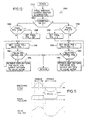
- the upper graph of Fig. 6 illustrates a typical breath cycle air flow.
- the flow rate of gas to the patient gradually increases to a maximum and then decreases.
- the patient typically experiences a slight pause before exhalation begins.
- the exhaled gas flow from the patient gradually increases to a maximum and then decreases again.
- a post-exhalation pause typically somewhat longer than the post-inhalation pause, follows exhalation. After the post-exhalation pause, the patient again then begins inhalation.
- the middle graph of Fig. 6 illustrates the nasal airway pressure presented to patient 36 during operation of apparatus 10.
- this middle graph illustrates an increase in the nasal airway pressure just prior to inhalation to a selected prescription pressure level sufficient to push surrounding tissue aside and open this airway.
- the set point pressure presented to the nasal airway is reduced so that exhalation occurs against a low or even zero pressure level relative to ambient.
- the nasal airway pressure is again increased prior to the next inhalation phase.
- blower unit 18 in one embodiment for use with the invention, produces a generally constant volume per unit time of breathable gas which is selectively vented through vent end 32.
- the vented gas volume is controlled by vent valve assembly 16.
- the bottom graph of Fig. 6 graphically depicts the various positions of valve element 46 in relation to vent end 32 in order to achieve the desired nasal airway pressure profile illustrated in the middle graph.
- controller 20 activates stepper motor 44 to rotate valve element 46 in a clockwise direction (as viewed in Fig. 5) in order to increase the nasal airway pressure to the desired set point as sensed by controller 20 by way of pneumatic line 40.
- gas output from blower unit 18 is inhaled by the patient.
- the controller then rotates valve element 46 in stepwise fashion further in the clockwise direction to reduce the amount of gas being vented.
- controller 20 begins to reverse the position of valve element 46 to vent additional gas for maintaining the set point pressure.
- controller 20 continues, in stepwise fashion, to rotate valve element 46 in the counterclockwise direction to vent additional amounts of gas for achieving a new lower set point pressure.
- controller 20 causes valve element 46 to further rotate in a clockwise direction to open vent end 32 even further.
- controller 20 rotates valve element 46 in a clockwise direction to decrease venting in order to maintain the lower set point pressure.
- controller 20 then causes valve element 46 to rotate further in the clockwise direction to increase the pressure to the higher pressure set point. This induces tension in the genioglossus muscle to open the airway in preparation for the next inhalation phase.
- controller 20 is able to track a patients breathing cycle by tracking the stepped positions of valve element 46 required to maintain the set point pressures. In this way, controller 20 is able to determine the end of respective inhalation/exhalation phases and to predict exhalation and inhalation interval times.
- controller 20 provides electrical outputs to control the speed of blower unit 18 and the position of stepper motor 44. Controller 20 receives electrical feedback from blower unit 18 indicative of the speed thereof, and a pneumatic input by way of pneumatic line 40 to indicate the pressure at nasal pillow 14 and thereby in the patient's nasal airway passages.
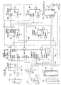
- Controller 20 includes pressure transducer circuit 700 (Fig. 7) for providing an electrical input indicative of the pressure at nasal pillow 14 to microcontroller circuit 800 (Fig. 8) which in turn provides outputs to blower motor circuit 900 (Fig. 9) and stepper motor circuit 1000 (Fig. 10). Additionally, controller 20 includes a conventional 120 v.a.c. to +5 v.d.c., +12 v.d.c., and +24 v.d.c. power supply (not shown) suitable for digital and analog, solid state integrated circuit components.
- Pressure transducer circuit 700 illustrated in Fig. 7 is typical of the pressure transducer circuit for both the single and dual conduit embodiments for use with the present invention. That is to say, the single conduit embodiment of Fig. 3 uses only one pressure transducer whereas the embodiment schematically illustrated in Fig. 4 uses two pressure transducers both using a circuit as illustrated in Fig. 7.
- the preferred pressure transducer includes SENSYM type SX01DN having a zero-to 70-cm. water operational range.
- the preferred transducer includes four strain gages arranged in a conventional Wheatstone bridge 701 having strain gages X1, X2, X3, and X4 presenting a nominal 4650 ohms each.
- Bridge 701 presents excitation terminal 702 connected to +12 v.d.c. and an opposed excitation terminal 704 connected to ground as shown.
- Bridge 701 produces outputs at terminals 706 and 708.
- Zero adjustment potentiometer 710 interconnects terminals 704 and 706.
- the output from terminal 708 is connected to the positive input terminal of operational amplifier 712 (one-half of Type LT1014).
- the output of operational amplifier 712 provides feedback to the negative input terminal thereof, and, by way of resistor R1 (1K ohms) supplies the positive input terminal of amplifier 714.
- the output is also connected to ground by way of resistor R2 (750K ohms).
- Strain gage bridge output terminal 706 is connected to the positive input terminal of operational amplifier 716 (the other half of unit LT1014).
- the output from amplifier 716 provides feedback to the negative input terminal thereof and is connected by way of resistor R3 (1K ohms) to the negative input terminal of amplifier 714.
- the output from amplifier 714 provides feedback to the negative input terminal thereof by way of resistor R4 (750K ohms).
- the output from amplifier 714 is also connected by way of resistor R5 (X ohms) to output terminal 718 which, by way of the circuitry just described, provides output between 0 and +5 v.d.c. corresponding to a pressure of 0 to 25 cm. water.
- a similar output is provided at a corresponding terminal 720 if a second pressure transducer is used.
- two transducers provide additional pressure information which allows more precise tracking of inhalation and exhalation gas flows of the patient, and thereby more precise breath cycle tracking.
- Fig. 8 is an electrical schematic diagram of microcontroller circuit 800 which includes microcontroller 802 (Intel Type 8097BH), programmable array logic (PAL) (Type PC16L8), erasable, programmable, read-only-memory (EPROM) (Type 27256), address latch 808 (Type 74HC373), random access memory (RAM) (Type 6264P), input/output serial data interface (RS232 Type MAX232), prescription (RX) switch array 814, and input data latch 816.
- microcontroller 802 Intel Type 8097BH
- PAL programmable array logic
- EPROM erasable, programmable, read-only-memory
- EPROM erasable, programmable, read-only-memory
- address latch 808 Type 74HC373
- RAM random access memory
- RS232 Type MAX232 prescription
- RX prescription
- Microcontroller 802 receives power (Vcc) at +5 v.d.c. at terminals VCC, VPD, BW, RDY, VPP, and VREF as shown. Ground is connected to terminals NMI, VSS, EA, and ANGND. Crystal 802 is coupled between terminals XTAL1 and XTAL2 as shown and to which respective grounded capacitors C1 and C2 (33 pF each) are respectively coupled for timing signals at 12 MHZ.
- Microcontroller 802 receives a reset signal at terminal RESET from reset subcircuit 820.
- power is supplied through resistor R5 (100K ohms) to grounded capacitor C3 (22 uF) and to the input terminals of SCHMITT trigger NAND gate 822.
- resistor R5 100K ohms
- C3 22 uF
- SCHMITT trigger NAND gate 822.
- the resultant input voltage to NAND 822 is low, and its output is logic high.
- This logic high output is supplied to output terminal 824 which provides a reset signal to blower motor circuit 900 as discussed further hereinbelow.
- the initially logic high output from NAND 822 is inverted by invertor 826 to provide a logic low signal to microcontroller terminal RESET which holds microcontroller 802 in reset until the charge on capacitor C3 builds to the trigger level of NAND 822.
- Reset circuit 820 also includes a normally open, reset switch 828 coupled across capacitor C3 which allows manual reset.
- Diode D1 is coupled access resistor R5 to provide a discharge path for C5 in the event of power off.
- Microcontroller 802 also receives a pressure transducer input at terminal ACH0 and also at ACH1 if a second transducer is used as in the dual-conduit embodiment.
- a pressure transducer input at terminal ACH0 and also at ACH1 if a second transducer is used as in the dual-conduit embodiment.
- one side of capacitor C4 (.005 nF) is connected to terminal 718 along with the anode of diode D2 and the cathode of diode D3.
- the other side of capacitor C4 and the anode of diode D3 are connected to ground as shown and the cathode of diode D2 is connected to a supply voltage Vcc.
- An identical circuit is provided for terminal 720 using diodes D4, D5 and capacitor C5.
- Microcontroller 802 includes internal analog-to-digital converters (ADC) which receive the respective analog inputs at terminals ACH0 and ACH1 and convert these to digital form for internal use in microcontroller
- Microcontroller 802 also receives an input at terminal HS1.0 which is a pulse signal from blower motor circuit 900 representative of the speed of blower unit 18, discussed further hereinbelow.
- Microcontroller 802 also uses a common address/data bus 830 which interconnects microcontroller 802 for data and address information flow with PAL 804, EPROM 806, address latch 808, RAM 810, and data latch 816 at the terminals as shown in Fig. 8.
- Fig. 8 also illustrates the other conventional interconnections between these components as shown.
- Microcontroller 802 provides a serial data output from terminal TXD to terminal 11 of interface 812 and receives data from terminal 12 thereof at microcontroller terminal RXD.
- Interface terminals 14 and 13 receive RS232 data in and out which enable remote reading and control of microcontroller 802 and thereby apparatus 10. This feature is particularly useful in a sleep laboratory, for example, for adjusting the prescription pressures in order to achieve the optimal therapy.
- Switch array 814 includes eight, selectable switches for providing input data representative of the desired prescription set point pressures for inhalation and exhalation.
- the top four switches are used to set the prescription inhalation pressure and the bottom four switches for prescription exhalation pressure. With four switches for each set point, sixteen possible settings are available ranging between 3 and 16 cm water for inhalation, and 0 and 14 cm water for exhalation.
- Data latch 816 is coupled with switch array 814 as shown and latches the prescription data upon receipt of the latch signal from terminal 12 of PAL 804. The prescription data is transmitted over bus 830.
- Microcontroller 802 also provides two additional outputs. The first of these is data to stepper motor circuit 1000 by way of six-line output bus 832 from microcontroller terminals P1.0-1.5 to output terminal 834. The second additional output is a pulse-width modulated signal (PWM) to blower motor circuit 900 by way of line 834 and output terminal 836.
- PWM pulse-width modulated signal
- Fig. 9 is an electrical schematic diagram representing blower motor circuit 900 which receives the pulse width modulated signal at terminal 836 from microcontroller 802, and also receives an inverted reset signal at terminal 824 from reset circuit 820. Blower motor circuit 900 also provides a pulse output signal at terminal 902 representative of the speed of blower motor 904 to microcontroller 802.
- the reset signal received at terminal 824 is connected to terminal 10 of motor driver 906 (Type UC3524A).
- the pulse width modulated signal from controller 802 at terminal 836 is provided to terminal 2 of driver 906 by way of low pass filter C6 (1.0 uF) and resister R7 (24.9K ohms).
- Driver terminal 7 is connected to ground by way of capacitor C7 (.003 uF), and terminal 6 is connected to ground by way of resistor R8 (49.9K ohms). Terminal 8 is connected to ground and terminal 15 receives power supply at +12 v.d.c. Driver terminal 12, 13, and 16 are connected to Vcc at +5 v.d.c.
- Motor driver 906 converts the input pulse-width modulated signal at 0-5 v.d.c. to a corresponding output at 0 to +12 v.d.c. at terminals 11 and 14 thereof to programmable array logic (PAL) (Type 16L8) terminal 1. These terminals are also connected to ground by way of resistor R9 (0.5 ohms).
- PAL 908 produces respective outputs at terminals 19 and 18 as two phase for the stator and rotor of brushless D.C. blower motor 904 (Fasco Corp. Type 70000-S517).
- the PAL 908 outputs are respective inputs to level converters 910 and 912 (MC14504) which shift the voltage level from +5 to +12 v.d.c.
- the +12 v.d.c. outputs from level converters 910 and 912 are in turn transmitted to the respective gates of field effect transistors (SENSFET) (Motorola SENSFET Type MTP40N06M) 914 and 916.
- SENSFET field effect transistors
- the respective drain terminals of SENSFETS 914 and 916 are respectively connected to terminals 0A and 0B of blower motor 904 and provide the respective phase inputs to the stator and rotor thereof.
- Power at +12 v.d.c. is additionally provided to level converters 910 and 912 and to common power terminal CP of blower motor 904.
- each SENSFET 914, 916 is connected to ground as shown.
- SENSFETS 914,916 each include an additional pair of outputs on lines 918 and 920 which provide a sampling of the current flow through the respective SENSFETS. These outputs are coupled across resistor R10 (100 ohms) to provide a current path for the current sample, and thereby a voltage representative thereof to terminals 3 and 4 of motor driver 906.
- Driver 906 is responsive to this input voltage representative of the current flow through blower motor 904 to reduce the duty cycle of the output at terminals 11 and 14 in the event of motor overcurrent.
- Blower motor 904 is additionally equipped with Hall effect transducer which is operable to provide a voltage pulse each time a magnetic pole of the motor stator passes thereby. These output pulses represent the speed of motor 904 and are provided at motor terminal HALL by way of line 922 to output terminal 902, and as feedback to motor driver 906. The output pulses representative of motor blower speed at terminal 902 are provided to microcontroller 802 at terminal HS1.0 thereof.
- the pulses representative of motor blower speed are converted to a representative voltage before input to motor driver terminals 1 and 9.
- line 922 is connected to one side of capacitor C8 (0.01 uF) the other side of which is connected to one side of resistor R11 (10K ohms), and to the anode of diode D6.
- resistor R11 (10K ohms)
- the other side of resistor R11 is connected to ground.
- the cathode of diode D6 is connected to one side of grounded capacitor C9 (0.1 uF), to grounded resistor R12 (1M ohms) and to one side of resistor R13 (100K ohms).
- the other side of resistor R13 is connected to one side of capacitor C10 (o.22 uF), to one side of resistor R14 (10M ohms), and to motor driver terminal 1 as input thereto.
- the other side of capacitor C10 and resistor R14 are connected to driver terminal 9.
- This network of components C8-C10, R11-R14, and diode D6 convert the frequency pulses on line 922 to a voltage representative thereof. That is to say, this network acts as a frequency-to-voltage converter owing to the large capacitance of capacitor C9 (0.1 uF) which provides a long time constant.
- the voltage value provided at motor driver terminals 1 and 9 provides feedback to an internal comparator which compares the voltage to a set point derived from the pulse width modulated signal received at terminal 2.
- Fig. 10 illustrates stepper motor circuit 1000 which activates stepper motor 44 to position valve element 46 in accordance with data received from microcontroller 802 at terminal 834 therefrom.
- Stepper motor 44 is preferably a VEXTA model available from Oriental Motor Company and is capable of providing one revolution in 400 "steps" and is also capable of half-stepping if needed.
- motor 44 is operable to shift one step upon the imposition of the next sequential voltage step pattern provided as input at terminal 834 over output bus 832.
- bus 832 includes six lines, which are pattern data for the driver chip.
- step pattern data is provided to step motor driver chip 1002 (Type S'GS' L298N) at terminals A, B, C, and D respectively from terminals P1.0-1.3 of microcontroller 802.
- Driver 1002 shifts the input data voltage from +5 v.d.c. to +12 v.d.c. for corresponding output at terminals 2, 3, 13, and 14 which are connected to stepper motor 44 to impose the step pattern thereon at +12 v.d.c.
- the anodes of diodes D7, 8, 9, and 10 are connected to the respective four output lines of driver 1002, and the cathodes thereof are connected to +12 v.d.c. for voltage pull-up.
- the cathodes of diodes D11, 12, 13, and 14 are connected respectively to the output lines, and the respective diode cathodes connected to ground as shown for voltage pull-down.
- +5 v.d.c is provided at driver terminal 9, +12 v.d.c. at driver terminal 4, and terminals 1, 8, and 15 are all connected to ground.
- Figs. 11-14 are computer program flowcharts illustrating the operative program for microcontroller 802.
- Fig. 11 illustrates the START-UP portion of the main routine of the computer program for operating microcontroller 802.
- the program enters at step 1102 which prompts controller 20 to shift vent valve assembly 16 to its "home" position.
- this step prompts microcontroller 802 to produce data of sequential pattern outputs by way of line 832 and terminal 834 to stepper motor control circuit 1000.
- stepper motor 44 This shifts stepper motor 44 to a mid-range position wherein valve element 46 blocks conduit ends 32 and 58 about half-way as shown in Fig. 5, or conduit end 32 alone in the single conduit embodiment.
- Step 1102 also initializes the variables, counters, interrupt routines, and so forth in the program.
- step 1104 to read the inhalation and exhalation prescription pressure values as set on switch array 814 and read by way of address data bus 830. These values are then stored in RAM. Step 1104 also prompts microcontroller 802 to set the operating speed of blower motor 904 in accordance with the prescription of pressure set on switch 814. The blower speed should be set at a level fast enough to ensure that sufficient ambient air volume is provided to conduit 12 such that the prescription pressure level can be attained during maximum inhalation. Blower motor speed data corresponding to prescription settings are stored preferably in a look-up table. Step 1104 also clears any value stored in the internal buffer at microcontroller terminal HS1.0.
- step 1106 enables the program's timed interrupts to begin timing.
- step 1108 the program sets the software flag "phase” equal to inhalation "I" which initializes the program from the inhalation phase of the patient's breathing cycle. This step also initializes the blower check counter at zero. As discussed further hereinbelow, the program reads the blower speed after 128 passes through the main loop.
- step 1110 which starts the internal analog-to-digital converter (ADC) connected to microcontroller input terminals ACH0 and ACH1.
- ADC analog-to-digital converter
- Step 1112 sets the pressure set point for the inhalation phase according to the inhalation prescription value set on switch array 814 according to data in a look-up table.
- This step also defines the start-up mode of the apparatus as continuous positive airway pressure (CPAP). That is to say, and as explained further hereinbelow, the program operates apparatus 10 in order to present a continuous positive pressure at the inhalation set point pressure for the first eight breaths of a patient.
- Step 1112 also initializes the breath counter at zero in preparation for counting patient breathing cycles.
- Step 1202 is the first step of this routine in which the program calculates the average pressure as sensed by pressure transducer 701 over eight ADC conversions. That is to say, microcontroller 802 includes an internal "ring" buffer which stores the eight most recent pressure readings received at microcontroller terminal ACH0 (and also ACH1 in the two-conduit embodiment). As discussed further hereinbelow, ADC interrupt routine converts the input analog values to digital form every 22 microseconds and continuously stores the most recent digital values in the ring buffer. Step 1020 calculates the average value by dividing the cumulative buffer value by eight. Step 1202 also calculates the deviation, that is, error, in the average pressure from the pressure set point.
- step 1204 which asks whether the magnitude of the error calculated in step 1202 is greater than allowed maximum error. This provides a so-called “dead band” to prevent the system from "hunting".
- step 1204 the program moves to step 1206 and calculates the number of steps and direction of stepper motor 44 required to correct the pressure deviation error. That is to say, depending upon the volume of air being produced by the blower, the fluid capacity of the system, and the leakage therefrom, the number of required steps can be determined approximately by reference to data previously stored in a look-up table.
- VALVE STEP routine 1300 sequentially presents the data patterns required to step the valve for the required number of steps in the direction determined in step 1206.
- step 1210 stores the number of valve steps and direction actually implemented in an internal valve slope buffer which continuously stores the previous eight movements of stepper motor 44.
- the slope of valve movement can be calculated by dividing the valve slope buffer sum by eight. This represents a slope because the eight values are stored at equal time intervals and thus the buffer sum divided by eight represents the first derivative of value movement.
- step 1212 which asks whether the phase flag is set for exhalation.
- the program was initialized with the phase flag set for inhalation, and so, during the first few passes through main loop 1200, the answer in 1212 is no and the program moves to step 1214 which asks whether the phase flag is set for inhalation. Because this flag is initialized as inhalation, the answer in step 1214 is yes and the program moves to step 1216.
- Step 1216 asks whether the variable "timer counter” is greater than the value for variable "inhalation end time", and whether the slope as calculated in step 1210 is less than or equal to -5.
- the variable "timer counter” (TMR CNT) is a software counter which was initialized at zero and increments every 13 milliseconds.
- the variable "inhalation end time” was initialized at a default value representing inhalation time equivalent to a predetermined average value. As discussed further hereinbelow, the variable “inhalation end time” is recalculated for each breath cycle after an initial eight passes through main loop 1200.
- Step 1216 operates to determine whether sufficient time has passed for normal inhalation to be complete as additionally confirmed by the value slope being less than -5 as illustrated by the slope of the value position curve at the end of inhalation in Fig. 6.
- step 1216 During the first few passes through main loop 1200, the answer in step 1216 is no and the program moves to step 1218 which asks whether the blower check counter, initialized at zero, is equal to 128. Until then, the answer in step 1218 is no and the program moves to step 1220 to increment the blower check counter.
- the program then loops back to step 1202 and repetitively executes steps 1202-1220 until the answer in step 1218 is yes whereupon the program moves to step 1222 to execute the sub-routine "CHECK BLOWER SPEED" 1200 as illustrated in Fig. 15. As discussed further hereinbelow, this step monitors the blower speed to ensure that it is running at the set point speed initially set in step 1104 in accordance with prescription settings. The program then returns to step 1224 to reset the blower check counter at zero.
- step 1216 After sufficient time has elapsed to exceed the default time set for the inhalation end time, and when the slope of the valve position curve is equal to or less than -5 indicating the end of patient inhalation, the answer in step 1216 is yes and the program moves to step 1218 which asks whether the mode of operation is set for inspiratory nasal air pressure (INAP).
- INAP inspiratory nasal air pressure
- step 1232 sets the variable "cycle time” equal to the current value existing on the timer counter. This step is entered at the end of each inhalation phase and marks the end of one breath cycle and the beginning of another. Thus, the time of one breath cycle, that is, cycle time, equals the time value existing on the timer counter which is reset to zero at the end of each breath cycle, also in step 1232.
- Step 1232 also sets a new inhalation interval time equal to the new cycle time divided by three. Statistically, inhalation time averages about 40% of a typical breathing cycle. Step 1232, however, sets the inhalation interval equal to 33% of the most recent cycle time in order to ensure that this value clocks out in step 1216 early, that is, before the end of anticipated actual inhalation time.
- Step 1232 also sets the variable "inhalation start time" equal to the new cycle time divided by two. With the beginning of a cycle marked as the end of an inhalation phase, the next inhalation start time would normally be expected to occur after 60% of the cycle time has elapsed. Step 1232, however, sets inhalation start time at 50%, that is earlier than the predicted inhalation time in order to ensure an increase in nasal pressure before inhalation would be expected to begin.
- step 1228 After main loop 1200 has detected eight breath cycles as indicated on the breath counter, the answer in step 1228 is no and the program moves to step 1234 which sets the operating mode as INAP.
- the eight cycle delay in setting the INAP mode ensures reliable data in tracking the breath cycle.
- step 1226 With the mode now set as INAP, the answer during the next pass at step 1226 is yes and the program moves to step 1236 to set the pressure set point equal to the exhaust prescription. That is to say, an inhalation phase has ended as determined in step 1216, eight breaths have been tracked as determined in step 1228, the mode is set as INAP which allows a decrease in pressure during exhalation. With these conditions satisfied, the controlled pressure set point is lowered to the prescribed exhaust prescription set point.
- the exhaust pressure would be prescribed at zero, that is ambient, so that the patient can exhale normally. In some circumstances, however, the therapist may desire a slight positive pressure during exhalation which is set on the lower four switches of switch array 814 (Fig. 8).
- Step 1236 also sets the phase flag for exhalation.
- step 1238 asks whether the current value on the timer counter is greater than or equal to the inhalation start time as previously set in step 1232.
- step 1238 asks whether the valve position slope is greater than seven which independently indicates the end of exhalation.
- the valve must step in the positive direction rapidly in order to restrict vent end 32 for maintaining the set point pressure. This rapid change indicates a positive slope greater than 70.
- step 1238 If the answer in step 1238 is no, the program continues to loop through until the answer is yes at which time the program moves to step 1240 to set the phase flag for inhalation, to set the pressure set point at the inhalation prescription value, and to set the value for the variable "inhalation end time" equal to the currently existing timer count plus the inhalation interval time.
- the existing value of the timer counter corresponds to the time elapsed since the beginning of the current breath cycle, which marked the end of the previous inhalation phase.
- the inhalation phase about to begin should end on or after the current timer count value plus the inhalation interval time.
- step 1240 provides a new value for inhalation interval time for use in step 1216.
- step 1216 for both the expiration of the inhalation end time and a slope less than or equal to -5.
- step 1238 in cooperation with the balance of the operating program, ensures that the inhalation set point pressure increases before the onset of patient inhalation.
- the end of exhalation can be detected. Marking the end of an exhalation phase ensures that this is a point in the breath cycle prior to the beginning of the next inhalation phase. Additionally, an increase in the pressure prior to inhalation is assured by monitoring whether the timer counter is greater than or equal to the predicted inhalation start time in step 1238.
- Fig. 13 illustrates VALVE STEP sub-routine 1300 which operates to impose sequentially the required step patterns on stepper motor 44 by way of stepper motor circuit 1000.
- Sub-routine 1300 enters at step 1302 by setting the variable "final valve position” equal to the current valve position plus (or minus) the valve correction required as determined in step 1206 (Fig. 2).
- Step 1302 also sets the variable "valve position” equal to the current valve position.
- step 1304 which asks whether the correction direction is greater than zero, that is, in a positive direction to restrict vent end 32, or in the opposite direction. If the answer in step 1304 is yes, the program moves to step 1306 which asks whether the final position as determined in step 1302 exceeds step 160. That is to say, this step determines whether the requested or desired final valve position is beyond the maximum allowed position. If yes, the program moves to step 1308 which sets the final valve position equal to 160.
- step 1310 the program moves to step 1310 to set the variable "valve position" equal to "valve position" plus one. In other words, the program increments stepper motor 44 one step at a time until the final position is achieved.
- step 1312 which asks whether the new valve position is less than or equal to the final valve position as determined in step 1302. If no, which indicates that the desired final valve position has been achieved, the program returns to main loop step 1210.
- step 1312 If the answer in step 1312 is yes, indicating that the final valve position has not yet been achieved the program moves to step 1314 which retrieves the step pattern for the next blower motor step from memory. The program then activates the lines of bus 832 in order to send this step pattern to stepper motor circuit 1000 and thereby to stepper motor 34.
- the program then loops back to step 1310 to continue executing step patterns one at a time in sequence until the final position is obtained.
- Step 1316 asks whether the final position determined in step 1302 is less than zero indicating a valve position beyond the allowable limits of travel. If yes, the program sets the final position equal to zero in step 1318.
- Step 1320 then decrements the "valve position" variable and step 1322 asks whether the newly determined “valve position" is greater than or equal to the final position desired. If yes, the step moves to program 1324 and then loops back to step 1322. If the answer is step 1322 is no, the program returns to main loop step 1210.
- Fig. 14 illustrates ADC interrupt sub-routine 1400 which has its interrupt executed every X micro-seconds for providing an analog-to-digital conversion for the pressure data received from pressure transducer circuit 700, and to store this data in memory.
- Subroutine 1400 enters at step 1402 which retrieves the current data from the ADC register internal to microcontroller 802. This data is then stored in the ADC buffer for use in step 1202 (Fig. 12) of the main loop. This data is stored at location "L" which is one of the eight buffer locations. The program then moves to step 1404 to increment location variable "L" so that the next set of ADC data is placed in the next buffer location.
- step 1406 which asks whether "L" is equal to eight which is greater than the number of locations provided in the ADC buffer. If yes, the program resets "L" at location zero which is the first location in the buffer. After step 1408, or if the answer in step 1406 is no, the program moves to step 1410 which instructs the ADC to begin another data conversion. The program then returns from the interrupt to the main loop.
- Fig. 15 illustrates CHECK BLOWER SPEED subroutine 1500 which is entered from step 1222 of main loop 1200, and enters at step 1502 which reads the current blower speed as received at microcontroller terminal HS1.0 from the Hall effect transducer in blower motor 94.
- the program then moves to step 1504 which retrieves the blower speed set point corresponding to the prescription inhalation pressure and compares the set point to the sensed lower speed.
- the program then moves to step 1506 which asks whether the blower speed is within a maximum error range of the set point speed. If no, the program adjusts, in step 1508, the pulse-width of the pulse width modulated signal produced at microcontroller terminal PWM and transmitted to blower motor circuit 900. After step 1508, or if the answer in step 1506 is yes, the program returns to the main loop.
- a sound analysis circuit receives input from a pressure sensor circuit by way of a terminal which delivers outputs to a microcontroller.
- sounds are pressure variations and as such the preferred pressure sensor circuit is also operable for sensing pressure variations representative of airway sounds and in converting these variations into representative signals at the terminal.
- the signals from a pressure sensor circuit are delivered to a preamplifier which boosts the signal level for delivery to a first low-pass filter, a first band-pass filter, a second band-pass filter and a high pass filter.
- the first low-pass filter is included to provide output "DC" to the microcontroller indicative of low frequency (subaudio) pressure variations and nasal pressure.
- the first and second band-pass filters, and the high-pass filter split the audio frequency spectrum into three components: 10-200Hz, 200-800 Hz, and 800+ Hz, respectively.
- the outputs from the first and second band-pass filters, and the high-pass filter pass through respective first, second and third rectifiers which in turn provide rectified outputs to second, third and fourth low-pass filters.
- Second, third and fourth low-pass filters convert the respective rectified inputs to equivalent D.C. voltage outputs "LOW”, "MED”, and "HI” which represent the respective audio spectral components.
- These three outputs along with output "DC” are provided as inputs to the microcontroller which uses internal analog-to-digital conversion to product digital data representative of the three spectrum components.
- a SOUND ANALYSIS subroutine is advantageously included as part of the program for operating the microcontroller in connection with the pressure variation aspect of the invention.
- the subroutine enters at a first step which initiates analog-to-digital conversion of the analog inputs "DC", "LOW”, “MED”, “HI” received from the sound analysis circuit.
- the first step is implemented a number of times (for example, ten times) for each inhalation and the conversion values averaged.
- the average values of the digital representations of DC, LOW, MED and HI are then used for the third, fourth and fifth steps as discussed further hereinbelow.
- the program then moves to a second step which sets the software variable "old state” (OS) equal to the variable “new state” (NS) determined in the previous passes through the program. This step then sets variable NS equal to zero.
- OS software variable
- NS new state
- the program asks whether input "DC" is greater than a predetermined threshold value. This threshold value is set at a level sufficient to indicate that detectable airway sounds are occurring. If the answer is no, the program returns to the main loop. If yes, the program moves to the fourth step in which, along with subsequent steps, conducts a spectral analysis of the airway sounds as determined by the sound analysis circuit. In particular, the fourth step asks whether input LOW is of a predetermined threshold. If yes, the program moves to a fifth step which increments variable NS by 1.
- the program moves to a sixth step which asks whether input MED is above its associated threshold. If yes, the program moves to a seventh step which increments variable NS by 2.
- the program moves to an eighth step which asks whether input HI is greater than its predetermined threshold. If yes, then a ninth step increments variable NS by 4.
- the program moves to a tenth step.
- the tenth step calculates the variable "transition" (T) as a function of variables OS and NS.
- T the variable "transition"
- Variable T provides a spectral quantification of the airway sounds for use in determining which action, if any, should be taken concerning the increase or decrease of the gas pressure applied to the respiratory passages of the patient.
- This determination occurs in an eleventh step by use of a so-called "action table” which is a look-up table stored in memory using variable T as a pointer.
- the preferred action table is incorporated as part of the disclosure hereof as Appendix I attached hereto.
- action-designated changes in pressure are in increments of 1.0 cm. water pressure.
- the action determined in the eleventh step is "none", which indicates that snoring sounds are not occurring, it is preferred in the twelfth step that the patient-applied the pressure be decreased by 0.5 cm. water.
- the program assures that the pressure is not maintained at a level greater than that necessary. For example, if the detected airway sounds prompts an increase in pressure, and the airway sounds then disappear, it may be that the pressure was increased slightly more than necessary. Accordingly, the program will automatically decrease the pressure over time in small increments until airway sounds are again detected.
- the embodiment described above monitors airway sounds in the preferred embodiment. It will be appreciated, however, that the pressure transducer circuit is sensitive to many types of pressure variations other than those associated with airway sounds. For example, the pressure transducer circuit could be used to detect inaudible vibrations or pressure variations associated with exhalation and inhalation. With this capability, much information can be garnered about a patient's respiration such as whether the patient's respiration is rhythmic, erratic, or apneic as well as breath rate, inhalation and exhalation durations, and flow rates. Hence, with this capability the patient's respiration can be properly characterized and aspects of the respiration quantified.
- this information can be stored in memory for subsequent downloading for use by a physician, for example, in diagnosing repsiratory afflictions and efficacy of treatment.
- a physician for example, in diagnosing repsiratory afflictions and efficacy of treatment.
- patient comfort is enhanced because only the minimum required pressure is imposed both during sleep and before the patient falls to sleep. With increased comfort, the patient is more likely to use the prescribed treatment on a sustained basis and thereby gain the maximum benefit therefrom.
- the nasal pillow is the preferred means for patient coupling in order to impose the higher breathable gas pressure on the respiratory passages of the patient.
- the present invention may be embodied with a nasal mask, or a full face mask which may be desired in certain situations such as the application of anesthesia as breathable gas as discussed above.
- the position of the vent valve assembly is varied in order to increase or decrease the pressure of the breathable gas applied to the patient's respiratory passages.
- the apparatus hereof includes the capability of varying the speed of the blower unit which could be used instead to selectively vary the applied pressure. This would eliminate the need for the vent valve and stepper motor and reduce the manufacturing cost which would be advantageous as another embodiment of the invention.
- the breathable gas may be compressed and stored in a storage bottle, for example.
- the preferred controller includes microcontroller 802 which is operated by a computer program.
- Other equivalent control means might include a custom designed chip with all functions implemented in hardware without a computer program.
- vent valve assembly 16 it is preferred to track the patient's breathing cycle by tracking the movement of vent valve assembly 16.
- the breath cycle can be tracked by other means such as monitoring chest contractions and expansion, breathing sounds, directly sensing genioglossus muscle activity, or some equivalent parameter indicative of a breathing cycle.
- some therapists may prefer that the apparatus start up in a low pressure or zero pressure mode while the breath cycle is initially tracked. This may provide further patient comfort in the use of the invention.
Claims (7)
- Vorrichtung zur Erleichterung der Atmung (10),
welche zur Verbindung mit einer an einen Patienten angeschlossenen Gas-Zufuhreinrichtung (14) eingerichtet ist und Mittel zur kontrollierten Überdruckbeaufschlagung wenigstens eines Abschnittes der Atmungswege eines Patienten mit einem atembaren Gas aus einer Quelle hierfür aufweist, wobei die Vorrichtung umfasst:a) Mittel zur Erfassung von mit der Atmung verbundenen Geräuschen des Patienten, wobei die Mittel Spektrumsignale erzeugen können, die für ein Spektrum von Frequenzen repräsentativ sind, welche in ihrer Summe die erfassten Geräusche bilden, undb) Steuerungsmittel, welche Mittel zum betriebsmäßigen Verbinden mit der Gas-Zufuhreinrichtung in Abhängigkeit von den von den Geräusch-Erfassungsmitteln empfangenen Spektrumsignalen umfassen, um den Gasdruck, welcher wenigstens einem Abschnitt der Atmungswege des Patienten zugeführt wird, gemäß den durch die Erfassungsmittel erfassten Geräusche einzustellen, wobei die Steuerungsmittel umfassen:i) Mittel zur Spektralanalyse, um eine spektrale Frequenzanalyse der Spektrumsignale zu erzeugen,ii) Speichermittel, um Daten abzuspeichern, welche für eine Vielzahl von Steuerungsvorgängen, die vorgegebenen Spektrumsignalen entsprechen, repräsentativ sind, undiii) Prozessormittel, welche auf die Spektralanalyse ansprechen, um Steuerungsvorgänge aus den Speichermitteln gemäß den Spektrumsignalen auszuwählen und um den Gasdruck gemäß den ausgewählten Steuerungsvorgängen einzustellen, damit das Auftreten eines Apnoe-Ereignisses verhindert wird. - Vorrichtung nach Anspruch 1, bei welcher die Geräusch-Erfassungsmittel einen Druck-Meßwandler (700) umfassen.
- Vorrichtung nach Anspruch 1, bei welcher die Geräusch-Erfassungsmittel ein Mikrofon umfassen.
- Vorrichtung nach Anspruch 1, bei welcher die Steuerungsmittel einen Mikroprozessor umfassen.
- Vorichtung nach Anspruch 1, bei welchem die Geräusch-Erfassungsmittel fähig sind, Schnarchgeräusche von dem Patienten zu erfassen.
- Vorrichtung nach Anspruch 5, bei welcher die Steuerungsmittel den Gasdruck wiederholt erhöhen können, bis die Schnarchgeräusche nicht mehr festgestellt werden.
- Vorrichtung nach Anspruch 5, bei welcher die Steuerungsmittel den Gasdruck beim Fehlen von Schnarchgeräuschen verringern können.
Applications Claiming Priority (5)
| Application Number | Priority Date | Filing Date | Title |
|---|---|---|---|
| US35414389A | 1989-05-19 | 1989-05-19 | |
| US354143 | 1989-05-19 | ||
| US51375790A | 1990-04-24 | 1990-04-24 | |
| US513757 | 1990-04-24 | ||
| EP90909914A EP0472664B1 (de) | 1989-05-19 | 1990-05-21 | Drucksystem für atmungswege |
Related Parent Applications (1)
| Application Number | Title | Priority Date | Filing Date |
|---|---|---|---|
| EP90909914A Division EP0472664B1 (de) | 1989-05-19 | 1990-05-21 | Drucksystem für atmungswege |
Publications (3)
| Publication Number | Publication Date |
|---|---|
| EP0875258A2 EP0875258A2 (de) | 1998-11-04 |
| EP0875258A3 EP0875258A3 (de) | 1999-02-03 |
| EP0875258B1 true EP0875258B1 (de) | 2004-11-24 |
Family
ID=26998264
Family Applications (2)
| Application Number | Title | Priority Date | Filing Date |
|---|---|---|---|
| EP90909914A Expired - Lifetime EP0472664B1 (de) | 1989-05-19 | 1990-05-21 | Drucksystem für atmungswege |
| EP98115332A Expired - Lifetime EP0875258B1 (de) | 1989-05-19 | 1990-05-21 | Drucksystem Für Atmungswege |
Family Applications Before (1)
| Application Number | Title | Priority Date | Filing Date |
|---|---|---|---|
| EP90909914A Expired - Lifetime EP0472664B1 (de) | 1989-05-19 | 1990-05-21 | Drucksystem für atmungswege |
Country Status (9)
| Country | Link |
|---|---|
| EP (2) | EP0472664B1 (de) |
| JP (1) | JP3090468B2 (de) |
| AT (2) | ATE177655T1 (de) |
| AU (1) | AU636628B2 (de) |
| CA (1) | CA2056401C (de) |
| DE (2) | DE69033005T2 (de) |
| DK (2) | DK0472664T3 (de) |
| ES (2) | ES2129393T3 (de) |
| WO (1) | WO1990014121A1 (de) |
Cited By (10)
| Publication number | Priority date | Publication date | Assignee | Title |
|---|---|---|---|---|
| US7668579B2 (en) | 2006-02-10 | 2010-02-23 | Lynn Lawrence A | System and method for the detection of physiologic response to stimulation |
| US7706852B2 (en) | 2006-01-30 | 2010-04-27 | Nellcor Puritan Bennett Llc | System and method for detection of unstable oxygen saturation |
| US7758503B2 (en) | 1997-01-27 | 2010-07-20 | Lynn Lawrence A | Microprocessor system for the analysis of physiologic and financial datasets |
| US8187201B2 (en) | 1997-01-27 | 2012-05-29 | Lynn Lawrence A | System and method for applying continuous positive airway pressure |
| US8275553B2 (en) | 2008-02-19 | 2012-09-25 | Nellcor Puritan Bennett Llc | System and method for evaluating physiological parameter data |
| US8365730B2 (en) | 2008-03-24 | 2013-02-05 | Covidien Lp | Method and system for classification of photo-plethysmographically detected respiratory effort |
| US8398555B2 (en) | 2008-09-10 | 2013-03-19 | Covidien Lp | System and method for detecting ventilatory instability |
| US9042952B2 (en) | 1997-01-27 | 2015-05-26 | Lawrence A. Lynn | System and method for automatic detection of a plurality of SPO2 time series pattern types |
| US9053222B2 (en) | 2002-05-17 | 2015-06-09 | Lawrence A. Lynn | Patient safety processor |
| US9468378B2 (en) | 1997-01-27 | 2016-10-18 | Lawrence A. Lynn | Airway instability detection system and method |
Families Citing this family (48)
| Publication number | Priority date | Publication date | Assignee | Title |
|---|---|---|---|---|
| US5259373A (en) * | 1989-05-19 | 1993-11-09 | Puritan-Bennett Corporation | Inspiratory airway pressure system controlled by the detection and analysis of patient airway sounds |
| US5134995A (en) * | 1989-05-19 | 1992-08-04 | Puritan-Bennett Corporation | Inspiratory airway pressure system with admittance determining apparatus and method |
| FR2674133B1 (fr) * | 1991-03-21 | 1993-06-11 | Taema | Installation de fourniture de surpression de gaz respiratoire et procede de commande d'une telle installation. |
| US5203343A (en) * | 1991-06-14 | 1993-04-20 | Board Of Regents, The University Of Texas System | Method and apparatus for controlling sleep disorder breathing |
| US5458137A (en) * | 1991-06-14 | 1995-10-17 | Respironics, Inc. | Method and apparatus for controlling sleep disorder breathing |
| US6085747A (en) * | 1991-06-14 | 2000-07-11 | Respironics, Inc. | Method and apparatus for controlling sleep disorder breathing |
| DE69231157T2 (de) * | 1991-11-14 | 2001-02-15 | Univ Technologies Int | Automatisches system zum erzeugen eines kontinuierlichen positiven atemwegsdruck |
| EP1149603A3 (de) * | 1991-12-20 | 2003-10-22 | Resmed Limited | Beatmungsgerät zur Erzeugung von kontinuierlichem positiven Atemwegdruck (CPAP) |
| US5803066A (en) * | 1992-05-07 | 1998-09-08 | New York University | Method and apparatus for optimizing the continuous positive airway pressure for treating obstructive sleep apnea |
| US5335654A (en) * | 1992-05-07 | 1994-08-09 | New York University | Method and apparatus for continuous adjustment of positive airway pressure for treating obstructive sleep apnea |
| US5490502A (en) * | 1992-05-07 | 1996-02-13 | New York University | Method and apparatus for optimizing the continuous positive airway pressure for treating obstructive sleep apnea |
| FR2692152B1 (fr) * | 1992-06-15 | 1997-06-27 | Pierre Medical Sa | Appareil d'aide a la respiration, notamment pour traiter l'apnee du sommeil. |
| FR2693910B1 (fr) * | 1992-07-23 | 1994-08-26 | Taema | Equipement et procédé de fourniture de doses d'au moins un gaz aux voies respiratoires d'un utilisateur. |
| US5342298A (en) * | 1992-07-31 | 1994-08-30 | Advanced Cardiovascular Systems, Inc. | Automated fluid pressure control system |
| FR2698274A1 (fr) * | 1992-11-20 | 1994-05-27 | Sefam | Dispositif d'assistance respiratoire. |
| EP2324765B1 (de) | 1993-11-05 | 2015-10-07 | ResMed Limited | Regelung bei einer Behandlung mit kontinuierlichem positiven Atemwegsdruck |
| US6675797B1 (en) | 1993-11-05 | 2004-01-13 | Resmed Limited | Determination of patency of the airway |
| DE69422900T2 (de) | 1993-12-01 | 2000-06-08 | Resmed Ltd | Vorrichtung zur Erzeugung eines kontinuierlichen positiven Atemwegdruckes (CPAP) |
| FR2724322A1 (fr) * | 1994-09-12 | 1996-03-15 | Pierre Medical Sa | Dispositif d'aide respiratoire commande en pression |
| US5452713A (en) * | 1994-10-24 | 1995-09-26 | Tuthill Corporation | Portable ventilator with reversible inlet fitting |
| AUPN236595A0 (en) | 1995-04-11 | 1995-05-11 | Rescare Limited | Monitoring of apneic arousals |
| JP3845736B2 (ja) | 1995-09-18 | 2006-11-15 | レスメッド・リミテッド | Cpap治療又は補助された人工呼吸における圧力制御 |
| AUPN973596A0 (en) | 1996-05-08 | 1996-05-30 | Resmed Limited | Control of delivery pressure in cpap treatment or assisted respiration |
| AUPO247496A0 (en) | 1996-09-23 | 1996-10-17 | Resmed Limited | Assisted ventilation to match patient respiratory need |
| AUPO301796A0 (en) | 1996-10-16 | 1996-11-07 | Resmed Limited | A vent valve apparatus |
| EP1009464A4 (de) * | 1997-05-16 | 2006-08-02 | Peter Craig Farrell | NASALE BEATMUNG ALS BEHANDLUNG VON Gehirnschlag. |
| US9521971B2 (en) | 1997-07-14 | 2016-12-20 | Lawrence A. Lynn | System and method for automatic detection of a plurality of SPO2 time series pattern types |
| US20070191697A1 (en) | 2006-02-10 | 2007-08-16 | Lynn Lawrence A | System and method for SPO2 instability detection and quantification |
| AUPP026997A0 (en) | 1997-11-07 | 1997-12-04 | Resmed Limited | Administration of cpap treatment pressure in presence of apnea |
| USD421298S (en) | 1998-04-23 | 2000-02-29 | Resmed Limited | Flow generator |
| DE19914667A1 (de) * | 1999-03-31 | 2000-11-23 | Andreas Velten | Verbindungsvorrichtung und Verfahren zur Herstellung individueller Beatmungsmasken |
| DE19949633C2 (de) * | 1999-10-14 | 2003-04-10 | Map Medizin Technologie Gmbh | Vorrichtung zur Zufuhr eines Atemgases unter Überdruck |
| AU9320301A (en) | 2000-09-28 | 2002-04-08 | Invacare Corp | Carbon dioxide-based bi-level cpap control |
| US20060195041A1 (en) | 2002-05-17 | 2006-08-31 | Lynn Lawrence A | Centralized hospital monitoring system for automatically detecting upper airway instability and for preventing and aborting adverse drug reactions |
| DE10118968B4 (de) * | 2001-04-18 | 2007-03-01 | The Scientific Consulting Group Gmbh | Verfahren zum Steuern des Solldrucks eines Geräts zur Durchführung der CPAP-Therapie sowie ein Gerät zur Durchführung der CPAP-Therapie |
| DE102004014619A1 (de) | 2003-03-24 | 2005-03-17 | Weinmann Geräte für Medizin GmbH + Co. KG | Verfahren und Vorrichtung zur Erkennung von Leckagen bei Einrichtungen zum Zuführen von Atemgasen |
| US7152598B2 (en) * | 2003-06-23 | 2006-12-26 | Invacare Corporation | System and method for providing a breathing gas |
| EP1784237A1 (de) * | 2004-06-18 | 2007-05-16 | Invacare Corporation | System und verfahren zur bereitstellung eines atemgases |
| US7882834B2 (en) | 2004-08-06 | 2011-02-08 | Fisher & Paykel Healthcare Limited | Autotitrating method and apparatus |
| NZ711441A (en) | 2005-10-14 | 2017-05-26 | Resmed Ltd | Flow generator message system |
| CA2696773A1 (en) | 2007-08-23 | 2009-02-26 | Invacare Corporation | Method and apparatus for adjusting desired pressure in positive airway pressure devices |
| WO2009137682A1 (en) | 2008-05-07 | 2009-11-12 | Lynn Lawrence A | Medical failure pattern search engine |
| US8302602B2 (en) | 2008-09-30 | 2012-11-06 | Nellcor Puritan Bennett Llc | Breathing assistance system with multiple pressure sensors |
| CN106955401B (zh) * | 2010-03-25 | 2020-11-06 | 瑞思迈巴黎股份有限公司 | 用于呼吸治疗装置的可呼吸气体进气口控制设备 |
| US8991392B1 (en) | 2010-12-21 | 2015-03-31 | Fisher & Paykel Healthcare Limited | Pressure adjustment method for CPAP machine |
| EP2755710B1 (de) | 2011-09-13 | 2018-05-23 | ResMed Limited | Lüftunganordnung für atemmaske |
| US10076619B2 (en) | 2012-09-11 | 2018-09-18 | Resmed Limited | Vent arrangement for respiratory mask |
| CN115607786B (zh) * | 2022-12-19 | 2023-03-31 | 广东九科医疗设备有限公司 | 一种呼吸机控制方法及呼吸机 |
Family Cites Families (30)
| Publication number | Priority date | Publication date | Assignee | Title |
|---|---|---|---|---|
| US3028873A (en) * | 1956-11-19 | 1962-04-10 | Sierra Eng Co | Non-rebreathing valve |
| US3741208A (en) * | 1971-02-23 | 1973-06-26 | B Jonsson | Lung ventilator |
| BE791154A (fr) * | 1971-11-10 | 1973-05-09 | Synthelabo | Respirateur a turbine |
| US3972327A (en) * | 1973-03-22 | 1976-08-03 | Hoffmann-La Roche Inc. | Respirator |
| US3840006A (en) * | 1973-04-26 | 1974-10-08 | Department Of Health Education | Respirator |
| CH568756A5 (de) * | 1973-09-07 | 1975-11-14 | Hoffmann La Roche | |
| US4156426A (en) * | 1977-08-11 | 1979-05-29 | Gold Lawrence W | Head-mounted oxygen-administration device |
| US4239039A (en) * | 1979-02-28 | 1980-12-16 | Thompson Harris A | Dual control valve for positive pressure artificial respiration apparatus |
| US4357936A (en) * | 1979-03-05 | 1982-11-09 | Bear Medical Systems, Inc. | Directional thermistor assist sensing |
| US4539984A (en) * | 1981-03-26 | 1985-09-10 | Vas Es Moszeripari Szovetkezet | Respirator device particularly for use in perinatal medicine |
| DE3276924D1 (en) * | 1981-04-24 | 1987-09-17 | Somed Pty Ltd | Device for treating snoring sickness |
| JPS58165823A (ja) * | 1982-03-29 | 1983-09-30 | 工業技術院長 | 呼吸監視装置 |
| US4508117A (en) * | 1982-09-13 | 1985-04-02 | Soxil S.P.A. | Apparatus for artificial pulmonary ventilation during anaesthesia and resuscitation |
| US4506666A (en) * | 1982-12-03 | 1985-03-26 | Kircaldie, Randall And Mcnab | Method and apparatus for rectifying obstructive apnea |
| DE3429345A1 (de) * | 1983-12-09 | 1985-06-13 | Drägerwerk AG, 2400 Lübeck | Kreislaufatemschutzgeraet fuer ueberdruckbetrieb |
| JPS60124940U (ja) * | 1984-02-02 | 1985-08-23 | シャープ株式会社 | 人工呼吸装置 |
| US4527557A (en) * | 1984-11-01 | 1985-07-09 | Bear Medical Systems, Inc. | Medical ventilator system |
| JPS6294175A (ja) * | 1985-10-18 | 1987-04-30 | 鳥取大学長 | 呼吸同調式ガス吹送装置および方法 |
| US4637385A (en) * | 1986-01-13 | 1987-01-20 | Tibor Rusz | Pulmonary ventilator controller |
| US4726366A (en) * | 1986-04-18 | 1988-02-23 | Life Products, Incorporated | Apparatus and method for controlling lung ventilation |
| FR2609623B1 (fr) * | 1987-01-15 | 1990-08-03 | Abensour David | Detecteur d'apnee pour enfant |
| WO1988010108A1 (en) * | 1987-06-26 | 1988-12-29 | Travenol Centre For Medical Research | Device for monitoring breathing during sleep and control of cpap treatment |
| US4807616A (en) * | 1987-07-09 | 1989-02-28 | Carmeli Adahan | Portable ventilator apparatus |
| US4782832A (en) * | 1987-07-30 | 1988-11-08 | Puritan-Bennett Corporation | Nasal puff with adjustable sealing means |
| US4802485A (en) * | 1987-09-02 | 1989-02-07 | Sentel Technologies, Inc. | Sleep apnea monitor |
| US4938212A (en) * | 1987-10-16 | 1990-07-03 | Puritan-Bennett Corporation | Inspiration oxygen saver |
| US4838258A (en) * | 1987-10-26 | 1989-06-13 | Gibeck-Dryden Corporation | Gas sampling lumen for breathing system |
| US4915103A (en) * | 1987-12-23 | 1990-04-10 | N. Visveshwara, M.D., Inc. | Ventilation synchronizer |
| US4883051A (en) * | 1988-02-18 | 1989-11-28 | Summa Vest, Inc. | Disposable breathing system and components |
| US4823788A (en) * | 1988-04-18 | 1989-04-25 | Smith Richard F M | Demand oxygen controller and respiratory monitor |
-
1990
- 1990-05-21 DK DK90909914T patent/DK0472664T3/da active
- 1990-05-21 ES ES90909914T patent/ES2129393T3/es not_active Expired - Lifetime
- 1990-05-21 CA CA002056401A patent/CA2056401C/en not_active Expired - Lifetime
- 1990-05-21 DE DE69033005T patent/DE69033005T2/de not_active Expired - Fee Related
- 1990-05-21 DK DK98115332T patent/DK0875258T3/da active
- 1990-05-21 ES ES98115332T patent/ES2235277T3/es not_active Expired - Lifetime
- 1990-05-21 EP EP90909914A patent/EP0472664B1/de not_active Expired - Lifetime
- 1990-05-21 AU AU59270/90A patent/AU636628B2/en not_active Withdrawn - After Issue
- 1990-05-21 DE DE69034178T patent/DE69034178T2/de not_active Expired - Fee Related
- 1990-05-21 AT AT90909914T patent/ATE177655T1/de not_active IP Right Cessation
- 1990-05-21 WO PCT/US1990/002800 patent/WO1990014121A1/en active IP Right Grant
- 1990-05-21 EP EP98115332A patent/EP0875258B1/de not_active Expired - Lifetime
- 1990-05-21 AT AT98115332T patent/ATE283085T1/de not_active IP Right Cessation
- 1990-05-21 JP JP02509801A patent/JP3090468B2/ja not_active Expired - Fee Related
Cited By (20)
| Publication number | Priority date | Publication date | Assignee | Title |
|---|---|---|---|---|
| US8152732B2 (en) | 1992-08-19 | 2012-04-10 | Lynn Lawrence A | Microprocessor system for the analysis of physiologic and financial datasets |
| US7758503B2 (en) | 1997-01-27 | 2010-07-20 | Lynn Lawrence A | Microprocessor system for the analysis of physiologic and financial datasets |
| US8187201B2 (en) | 1997-01-27 | 2012-05-29 | Lynn Lawrence A | System and method for applying continuous positive airway pressure |
| US8241213B2 (en) | 1997-01-27 | 2012-08-14 | Lynn Lawrence A | Microprocessor system for the analysis of physiologic datasets |
| US9468378B2 (en) | 1997-01-27 | 2016-10-18 | Lawrence A. Lynn | Airway instability detection system and method |
| US9042952B2 (en) | 1997-01-27 | 2015-05-26 | Lawrence A. Lynn | System and method for automatic detection of a plurality of SPO2 time series pattern types |
| US8932227B2 (en) | 2000-07-28 | 2015-01-13 | Lawrence A. Lynn | System and method for CO2 and oximetry integration |
| US8862196B2 (en) | 2001-05-17 | 2014-10-14 | Lawrence A. Lynn | System and method for automatic detection of a plurality of SP02 time series pattern types |
| US10297348B2 (en) | 2001-05-17 | 2019-05-21 | Lawrence A. Lynn | Patient safety processor |
| US10032526B2 (en) | 2001-05-17 | 2018-07-24 | Lawrence A. Lynn | Patient safety processor |
| US9053222B2 (en) | 2002-05-17 | 2015-06-09 | Lawrence A. Lynn | Patient safety processor |
| US7706852B2 (en) | 2006-01-30 | 2010-04-27 | Nellcor Puritan Bennett Llc | System and method for detection of unstable oxygen saturation |
| US8728001B2 (en) | 2006-02-10 | 2014-05-20 | Lawrence A. Lynn | Nasal capnographic pressure monitoring system |
| US7668579B2 (en) | 2006-02-10 | 2010-02-23 | Lynn Lawrence A | System and method for the detection of physiologic response to stimulation |
| US8781753B2 (en) | 2008-02-19 | 2014-07-15 | Covidien Lp | System and method for evaluating physiological parameter data |
| US8275553B2 (en) | 2008-02-19 | 2012-09-25 | Nellcor Puritan Bennett Llc | System and method for evaluating physiological parameter data |
| US9044558B2 (en) | 2008-03-24 | 2015-06-02 | Covidien Lp | Method and system for classification of photo-plethysmographically detected respiratory effort |
| US8365730B2 (en) | 2008-03-24 | 2013-02-05 | Covidien Lp | Method and system for classification of photo-plethysmographically detected respiratory effort |
| US10532170B2 (en) | 2008-03-24 | 2020-01-14 | Covidien Lp | Method and system for classification of photo-plethysmographically detected respiratory effort |
| US8398555B2 (en) | 2008-09-10 | 2013-03-19 | Covidien Lp | System and method for detecting ventilatory instability |
Also Published As
| Publication number | Publication date |
|---|---|
| ATE283085T1 (de) | 2004-12-15 |
| EP0875258A3 (de) | 1999-02-03 |
| EP0875258A2 (de) | 1998-11-04 |
| ES2235277T3 (es) | 2005-07-01 |
| EP0472664A1 (de) | 1992-03-04 |
| ES2129393T3 (es) | 1999-06-16 |
| DE69034178D1 (de) | 2004-12-30 |
| EP0472664B1 (de) | 1999-03-17 |
| AU636628B2 (en) | 1993-05-06 |
| EP0472664A4 (en) | 1993-09-15 |
| CA2056401C (en) | 1997-05-27 |
| DK0472664T3 (da) | 1999-10-11 |
| DE69034178T2 (de) | 2005-09-22 |
| DE69033005D1 (de) | 1999-04-22 |
| JP3090468B2 (ja) | 2000-09-18 |
| ATE177655T1 (de) | 1999-04-15 |
| JPH04505572A (ja) | 1992-10-01 |
| WO1990014121A1 (en) | 1990-11-29 |
| AU5927090A (en) | 1990-12-18 |
| DE69033005T2 (de) | 1999-09-23 |
| DK0875258T3 (da) | 2005-04-04 |
Similar Documents
| Publication | Publication Date | Title |
|---|---|---|
| EP0875258B1 (de) | Drucksystem Für Atmungswege | |
| EP0563044B1 (de) | Drucksystem für atmungswege | |
| US5845636A (en) | Method and apparatus for maintaining patient airway patency | |
| US5794614A (en) | Apparatus for compensating for flow and pressure variances in pneumatic circuits | |
| EP0610405B1 (de) | Vorrichtung zur behandlung des atemstillstandes im schlaf | |
| USRE35295E (en) | Sleep apnea treatment apparatus | |
| CA2160509C (en) | Standby control for cpap apparatus | |
| US6213119B1 (en) | Inspiratory duration in CPAP or assisted respiration treatment | |
| EP0788805A2 (de) | Steuerung einer Vorrichtung zur Aufrechthaltung eines kontinuierlichen positiven Atemwegdrucks | |
| AU662039B2 (en) | Inspiratory airway pressure system | |
| EP2523715A2 (de) | Servoventilation mit unterdruckunterstützung | |
| AU699726B2 (en) | Inspiratory duration in CPAP or assisted respiration treatment |
Legal Events
| Date | Code | Title | Description |
|---|---|---|---|
| PUAI | Public reference made under article 153(3) epc to a published international application that has entered the european phase |
Free format text: ORIGINAL CODE: 0009012 |
|
| 17P | Request for examination filed |
Effective date: 19980814 |
|
| AC | Divisional application: reference to earlier application |
Ref document number: 472664 Country of ref document: EP |
|
| AK | Designated contracting states |
Kind code of ref document: A2 Designated state(s): AT BE CH DE DK ES FR GB IT LI LU NL SE |
|
| PUAL | Search report despatched |
Free format text: ORIGINAL CODE: 0009013 |
|
| AK | Designated contracting states |
Kind code of ref document: A3 Designated state(s): AT BE CH DE DK ES FR GB IT LI LU NL SE |
|
| RIN1 | Information on inventor provided before grant (corrected) |
Inventor name: LOETHEN, STEVEN W. Inventor name: ORLT, YURI G. Inventor name: SNOOK, JAMES A. Inventor name: GRUENKE, ROGER A. Inventor name: TRIMBLE, RUSSELL L. MEDVANTAGE INT. INC |
|
| 17Q | First examination report despatched |
Effective date: 20020403 |
|
| GRAP | Despatch of communication of intention to grant a patent |
Free format text: ORIGINAL CODE: EPIDOSNIGR1 |
|
| GRAS | Grant fee paid |
Free format text: ORIGINAL CODE: EPIDOSNIGR3 |
|
| GRAA | (expected) grant |
Free format text: ORIGINAL CODE: 0009210 |
|
| AC | Divisional application: reference to earlier application |
Ref document number: 0472664 Country of ref document: EP Kind code of ref document: P |
|
| AK | Designated contracting states |
Kind code of ref document: B1 Designated state(s): AT BE CH DE DK ES FR GB IT LI LU NL SE |
|
| REG | Reference to a national code |
Ref country code: GB Ref legal event code: FG4D |
|
| REG | Reference to a national code |
Ref country code: CH Ref legal event code: EP |
|
| REF | Corresponds to: |
Ref document number: 69034178 Country of ref document: DE Date of ref document: 20041230 Kind code of ref document: P |
|
| REG | Reference to a national code |
Ref country code: CH Ref legal event code: NV Representative=s name: E. BLUM & CO. PATENTANWAELTE |
|
| REG | Reference to a national code |
Ref country code: SE Ref legal event code: TRGR |
|
| REG | Reference to a national code |
Ref country code: DK Ref legal event code: T3 |
|
| REG | Reference to a national code |
Ref country code: ES Ref legal event code: FG2A Ref document number: 2235277 Country of ref document: ES Kind code of ref document: T3 |
|
| ET | Fr: translation filed | ||
| PLBE | No opposition filed within time limit |
Free format text: ORIGINAL CODE: 0009261 |
|
| STAA | Information on the status of an ep patent application or granted ep patent |
Free format text: STATUS: NO OPPOSITION FILED WITHIN TIME LIMIT |
|
| 26N | No opposition filed |
Effective date: 20050825 |
|
| PGFP | Annual fee paid to national office [announced via postgrant information from national office to epo] |
Ref country code: ES Payment date: 20070528 Year of fee payment: 18 |
|
| PGFP | Annual fee paid to national office [announced via postgrant information from national office to epo] |
Ref country code: SE Payment date: 20070529 Year of fee payment: 18 |
|
| PGFP | Annual fee paid to national office [announced via postgrant information from national office to epo] |
Ref country code: CH Payment date: 20070530 Year of fee payment: 18 |
|
| PGFP | Annual fee paid to national office [announced via postgrant information from national office to epo] |
Ref country code: DK Payment date: 20070531 Year of fee payment: 18 |
|
| PGFP | Annual fee paid to national office [announced via postgrant information from national office to epo] |
Ref country code: LU Payment date: 20070605 Year of fee payment: 18 |
|
| PGFP | Annual fee paid to national office [announced via postgrant information from national office to epo] |
Ref country code: BE Payment date: 20070615 Year of fee payment: 18 |
|
| REG | Reference to a national code |
Ref country code: CH Ref legal event code: PFA Owner name: PURITAN BENNETT CORPORATION Free format text: PURITAN BENNETT CORPORATION#10800 PFLUMM ROAD#LENEXA, KS 66215-2198 (US) -TRANSFER TO- PURITAN BENNETT CORPORATION#10800 PFLUMM ROAD#LENEXA, KS 66215-2198 (US) |
|
| PGFP | Annual fee paid to national office [announced via postgrant information from national office to epo] |
Ref country code: IT Payment date: 20070526 Year of fee payment: 18 |
|
| PGFP | Annual fee paid to national office [announced via postgrant information from national office to epo] |
Ref country code: AT Payment date: 20080502 Year of fee payment: 19 |
|
| PGFP | Annual fee paid to national office [announced via postgrant information from national office to epo] |
Ref country code: NL Payment date: 20080524 Year of fee payment: 19 Ref country code: DE Payment date: 20080630 Year of fee payment: 19 |
|
| BERE | Be: lapsed |
Owner name: *PURITAN BENNETT CORP. Effective date: 20080531 |
|
| PGFP | Annual fee paid to national office [announced via postgrant information from national office to epo] |
Ref country code: GB Payment date: 20080529 Year of fee payment: 19 |
|
| REG | Reference to a national code |
Ref country code: CH Ref legal event code: PL |
|
| REG | Reference to a national code |
Ref country code: DK Ref legal event code: EBP |
|
| PG25 | Lapsed in a contracting state [announced via postgrant information from national office to epo] |
Ref country code: LI Free format text: LAPSE BECAUSE OF NON-PAYMENT OF DUE FEES Effective date: 20080531 Ref country code: CH Free format text: LAPSE BECAUSE OF NON-PAYMENT OF DUE FEES Effective date: 20080531 |
|
| PG25 | Lapsed in a contracting state [announced via postgrant information from national office to epo] |
Ref country code: BE Free format text: LAPSE BECAUSE OF NON-PAYMENT OF DUE FEES Effective date: 20080531 |
|
| PG25 | Lapsed in a contracting state [announced via postgrant information from national office to epo] |
Ref country code: DK Free format text: LAPSE BECAUSE OF NON-PAYMENT OF DUE FEES Effective date: 20080531 |
|
| REG | Reference to a national code |
Ref country code: ES Ref legal event code: FD2A Effective date: 20080522 |
|
| PG25 | Lapsed in a contracting state [announced via postgrant information from national office to epo] |
Ref country code: IT Free format text: LAPSE BECAUSE OF NON-PAYMENT OF DUE FEES Effective date: 20080521 |
|
| PG25 | Lapsed in a contracting state [announced via postgrant information from national office to epo] |
Ref country code: ES Free format text: LAPSE BECAUSE OF NON-PAYMENT OF DUE FEES Effective date: 20080522 |
|
| GBPC | Gb: european patent ceased through non-payment of renewal fee |
Effective date: 20090521 |
|
| PG25 | Lapsed in a contracting state [announced via postgrant information from national office to epo] |
Ref country code: AT Free format text: LAPSE BECAUSE OF NON-PAYMENT OF DUE FEES Effective date: 20090521 |
|
| NLV4 | Nl: lapsed or anulled due to non-payment of the annual fee |
Effective date: 20091201 |
|
| PG25 | Lapsed in a contracting state [announced via postgrant information from national office to epo] |
Ref country code: NL Free format text: LAPSE BECAUSE OF NON-PAYMENT OF DUE FEES Effective date: 20091201 |
|
| REG | Reference to a national code |
Ref country code: FR Ref legal event code: ST Effective date: 20100129 |
|
| PG25 | Lapsed in a contracting state [announced via postgrant information from national office to epo] |
Ref country code: FR Free format text: LAPSE BECAUSE OF NON-PAYMENT OF DUE FEES Effective date: 20090602 |
|
| PGFP | Annual fee paid to national office [announced via postgrant information from national office to epo] |
Ref country code: FR Payment date: 20080519 Year of fee payment: 19 |
|
| PG25 | Lapsed in a contracting state [announced via postgrant information from national office to epo] |
Ref country code: GB Free format text: LAPSE BECAUSE OF NON-PAYMENT OF DUE FEES Effective date: 20090521 |
|
| PG25 | Lapsed in a contracting state [announced via postgrant information from national office to epo] |
Ref country code: LU Free format text: LAPSE BECAUSE OF NON-PAYMENT OF DUE FEES Effective date: 20080521 Ref country code: DE Free format text: LAPSE BECAUSE OF NON-PAYMENT OF DUE FEES Effective date: 20091201 |
|
| PG25 | Lapsed in a contracting state [announced via postgrant information from national office to epo] |
Ref country code: SE Free format text: LAPSE BECAUSE OF NON-PAYMENT OF DUE FEES Effective date: 20080522 |