EP0874789B1 - Schutz von porösen körpern gegen oxidation - Google Patents
Schutz von porösen körpern gegen oxidation Download PDFInfo
- Publication number
- EP0874789B1 EP0874789B1 EP97900018A EP97900018A EP0874789B1 EP 0874789 B1 EP0874789 B1 EP 0874789B1 EP 97900018 A EP97900018 A EP 97900018A EP 97900018 A EP97900018 A EP 97900018A EP 0874789 B1 EP0874789 B1 EP 0874789B1
- Authority
- EP
- European Patent Office
- Prior art keywords
- treating
- liquid
- treating liquid
- temperature
- treated
- Prior art date
- Legal status (The legal status is an assumption and is not a legal conclusion. Google has not performed a legal analysis and makes no representation as to the accuracy of the status listed.)
- Expired - Lifetime
Links
Images
Classifications
-
- C—CHEMISTRY; METALLURGY
- C04—CEMENTS; CONCRETE; ARTIFICIAL STONE; CERAMICS; REFRACTORIES
- C04B—LIME, MAGNESIA; SLAG; CEMENTS; COMPOSITIONS THEREOF, e.g. MORTARS, CONCRETE OR LIKE BUILDING MATERIALS; ARTIFICIAL STONE; CERAMICS; REFRACTORIES; TREATMENT OF NATURAL STONE
- C04B41/00—After-treatment of mortars, concrete, artificial stone or ceramics; Treatment of natural stone
- C04B41/009—After-treatment of mortars, concrete, artificial stone or ceramics; Treatment of natural stone characterised by the material treated
-
- B—PERFORMING OPERATIONS; TRANSPORTING
- B05—SPRAYING OR ATOMISING IN GENERAL; APPLYING FLUENT MATERIALS TO SURFACES, IN GENERAL
- B05C—APPARATUS FOR APPLYING FLUENT MATERIALS TO SURFACES, IN GENERAL
- B05C3/00—Apparatus in which the work is brought into contact with a bulk quantity of liquid or other fluent material
- B05C3/02—Apparatus in which the work is brought into contact with a bulk quantity of liquid or other fluent material the work being immersed in the liquid or other fluent material
- B05C3/09—Apparatus in which the work is brought into contact with a bulk quantity of liquid or other fluent material the work being immersed in the liquid or other fluent material for treating separate articles
-
- C—CHEMISTRY; METALLURGY
- C04—CEMENTS; CONCRETE; ARTIFICIAL STONE; CERAMICS; REFRACTORIES
- C04B—LIME, MAGNESIA; SLAG; CEMENTS; COMPOSITIONS THEREOF, e.g. MORTARS, CONCRETE OR LIKE BUILDING MATERIALS; ARTIFICIAL STONE; CERAMICS; REFRACTORIES; TREATMENT OF NATURAL STONE
- C04B41/00—After-treatment of mortars, concrete, artificial stone or ceramics; Treatment of natural stone
- C04B41/45—Coating or impregnating, e.g. injection in masonry, partial coating of green or fired ceramics, organic coating compositions for adhering together two concrete elements
- C04B41/4572—Partial coating or impregnation of the surface of the substrate
-
- C—CHEMISTRY; METALLURGY
- C04—CEMENTS; CONCRETE; ARTIFICIAL STONE; CERAMICS; REFRACTORIES
- C04B—LIME, MAGNESIA; SLAG; CEMENTS; COMPOSITIONS THEREOF, e.g. MORTARS, CONCRETE OR LIKE BUILDING MATERIALS; ARTIFICIAL STONE; CERAMICS; REFRACTORIES; TREATMENT OF NATURAL STONE
- C04B41/00—After-treatment of mortars, concrete, artificial stone or ceramics; Treatment of natural stone
- C04B41/80—After-treatment of mortars, concrete, artificial stone or ceramics; Treatment of natural stone of only ceramics
- C04B41/81—Coating or impregnation
-
- C—CHEMISTRY; METALLURGY
- C25—ELECTROLYTIC OR ELECTROPHORETIC PROCESSES; APPARATUS THEREFOR
- C25C—PROCESSES FOR THE ELECTROLYTIC PRODUCTION, RECOVERY OR REFINING OF METALS; APPARATUS THEREFOR
- C25C3/00—Electrolytic production, recovery or refining of metals by electrolysis of melts
- C25C3/06—Electrolytic production, recovery or refining of metals by electrolysis of melts of aluminium
- C25C3/08—Cell construction, e.g. bottoms, walls, cathodes
- C25C3/12—Anodes
- C25C3/125—Anodes based on carbon
-
- C—CHEMISTRY; METALLURGY
- C04—CEMENTS; CONCRETE; ARTIFICIAL STONE; CERAMICS; REFRACTORIES
- C04B—LIME, MAGNESIA; SLAG; CEMENTS; COMPOSITIONS THEREOF, e.g. MORTARS, CONCRETE OR LIKE BUILDING MATERIALS; ARTIFICIAL STONE; CERAMICS; REFRACTORIES; TREATMENT OF NATURAL STONE
- C04B2111/00—Mortars, concrete or artificial stone or mixtures to prepare them, characterised by specific function, property or use
- C04B2111/00474—Uses not provided for elsewhere in C04B2111/00
- C04B2111/00853—Uses not provided for elsewhere in C04B2111/00 in electrochemical cells or batteries, e.g. fuel cells
-
- C—CHEMISTRY; METALLURGY
- C04—CEMENTS; CONCRETE; ARTIFICIAL STONE; CERAMICS; REFRACTORIES
- C04B—LIME, MAGNESIA; SLAG; CEMENTS; COMPOSITIONS THEREOF, e.g. MORTARS, CONCRETE OR LIKE BUILDING MATERIALS; ARTIFICIAL STONE; CERAMICS; REFRACTORIES; TREATMENT OF NATURAL STONE
- C04B2111/00—Mortars, concrete or artificial stone or mixtures to prepare them, characterised by specific function, property or use
- C04B2111/00474—Uses not provided for elsewhere in C04B2111/00
- C04B2111/0087—Uses not provided for elsewhere in C04B2111/00 for metallurgical applications
- C04B2111/00879—Non-ferrous metallurgy
Definitions
- the invention relates generally to a method of treating open-pored porous bodies which are to be exposed to oxidising conditions at high temperatures so as to protect the bodies against oxidation or other chemical attack in said high temperature oxidising conditions, in particular the treatment of prebaked carbon components of aluminium production cells, such as anode blocks or cathode blocks or cell side walls.
- the invention also relates to an apparatus for carrying out this method and use of the apparatus for applying a treating liquid to a prebaked carbon component of an aluminium production cell.
- U.S. Patent 5,486,278 (Manganiello et al) (family member of WO 94/28200) discloses treating a prebaked carbon-based anode of an electrolytic cell for the production of aluminium, in particular by the electrolysis of alumina in a molten fluoride electrolyte, over its sides and top to improve the resistance thereof to erosion and corrosion during operation of the cell by air and oxidising gases released at the anode, by immersing the anode in a boron-containing solution containing 5-60 weight% of H 3 BO 3 or B 2 O 3 in methanol, ethylene glycol, glycerin or water with a surface-active agent, e.g. at 80° to 120°C.
- a surface-active agent e.g. at 80° to 120°C.
- the boron-containing solution is impregnated to a depth of usually about 2-5 cm over the top and side surfaces of the anode to be protected, producing a concentration of boron in the impregnated surface from 100 ppm to 0.35%.
- the same treatment can be applied to cell sidewalls.
- U.S. Patent 5,534,130 (Sekhar) describes the protection of the cell sidewalls of aluminium production cells by impregnating them with agents based on aluminium phosphate. Again, it would be desirable to perfect ways of applying this method in an efficient manner.
- a particular object of the invention is to provide a method which can use a hot treating liquid in a very efficient manner, without necessarily heating the treated body substantially above ambient temperatures.
- the invention provides a method of impregnating an open-pored porous body with a hot treating liquid containing a dissolved treating agent to produce within the body a protective layer to a desired depth.
- This method comprises impregnating a hot non-saturated treating liquid into the surface of the porous body assisted by the application of a pressure differential.
- the applied treating liquid is at a temperature above that of the body and the concentration of the treating agent in the applied liquid is such that cooling of the applied liquid as it impregnates the pores of the body causes precipitation of the treating agent in the pores to the desired depth.
- the method according to the invention comprises firstly bringing the surface of the body into contact with a hot liquid containing a dissolved treating agent at a concentration below saturation and at a temperature well above the temperature of the body.
- concentration of treating agent in the hot liquid is such that when the liquid is cooled down to the temperature of the body the liquid saturates and treating agent precipitates.
- a pressure differential is then applied to cause the hot non-saturated treating liquid contacting the body to impregnate into the surface pores of the body.
- the treating liquid impregnates the pores of the body, it cools and deposits, within pores of the body underneath the surface, a layer of the treating agent precipitated from the impregnation liquid.
- Some treating agent may also cover the outside of the body's surface.
- the treating agent When, later, during use, the body is exposed to high temperatures particularly under oxidising conditions, this layer of the treating agent precipitated inside the body underneath its surface forms a protective layer in the surface pores which protects the body against oxidation or other chemical attack.
- the treating agent contains a soluble boron compound which forms an impervious viscous protective layer which is self forming above about 400°C.
- the treating liquid in contact with the body is usually at least 5°C and in many cases at least 10°C above the temperature at which the treating liquid is saturated with the dissolved treating agent for its given concentration.
- the treating liquid is at a temperature well above that of the body to be treated, i.e. usually at least 20°C above and conveniently 40°C or more above.
- the treating liquid is at a temperature in the range 60° to 120°C, whereas the body can be at ambient temperature or just above, say from about 20°C to 50°C.
- the applied treating liquid which is in contact with the body can be maintained at a more-or-less constant temperature by heating it to compensate for heat loss due to contact of the treating liquid with the body.
- the treating time can be reduced to a few minutes, which is a great improvement over the previous impregnation techniques.
- the method permits treatment of only a selected part of the body, in particular by using a specially designed apparatus, described below.
- the treated anode or other body Due to the rapidity of the impregnation process, the treated anode or other body only takes up a small quantity of heat, so the process is very energy efficient.
- the treated carbon bodies typically have an overall porosity in the range 20-24%, of which about 10-12% is open porosity.
- the penetration depth can be of the order of 0.5 to 3 cm.
- the treating agent may also extend to and even cover the bodies' outer surface.
- treating liquid is circulated by the following arrangement. Hot treating liquid is supplied from a reservoir and, after treatment of the body, non-impregnated treating liquid is returned back to the reservoir.
- the treating liquid in the reservoir is stirred and heated to maintain a desired temperature.
- Components of the treating liquid can be added to the reservoir to compensate for consumption of the treating liquid in the treating process.
- Another inventive aspect is a method of supplying the treating liquid which comprises providing a saturated solution of the treating agent at a given temperature, and deriving, from said saturated solution, a non-saturated solution of the treating agent. The non-saturated treating solution is then supplied as the treating liquid to treat the body.
- the non-saturated solution is obtained by increasing the temperature of the solution.
- the non-saturated solution contains the treating agent at the same concentration as the saturated solution (which corresponds to the saturation concentration at said given temperature) but is simply at a higher temperature.
- the treating liquid preferably contains an oxidation retardant agent for impregnating the part of the body to be treated, in particular at least one soluble compound of boron and/or phosphorous for improving the resistance to oxidation of the carbon.
- Preferred oxidation retardant agents for application to aluminium production anodes are boron containing liquids based on B 2 O 3 , boric acid, tetraboric acid, salts of said acids or boron silicate.
- These boron containing agents such as B 2 O 3 act as catalytic oxygen inhibitors when impregnated/dispersed in carbon.
- they when they are densely applied they form a vitreous impervious layer in the surface pores at temperatures above about 400°C.
- Such a layer acts as a barrier to protect the pores of a carbon body from oxidation.
- Such viscous layers act mainly by a barrier effect to inhibit oxidation. This is different to the effect of deeply impregnated boron compounds whose effect is principally as an anti-catalyst.
- boron silicate and silica are also suitable for producing viscous protective layers at the operating temperatures, especially in combination with boron compounds where an excess of the boron compound (in particular boric acid) will lead to the formation of borosilicate glass.
- the silicon compounds alone are not effective against oxidation and provide no anti-catlytic effect, when combined with boron compounds the resulting glassy material provides improved protection.
- Alternative treating liquids are liquids based on phosphates of aluminium for example selected from the group consisting of monoaluminium phosphate, aluminium phosphate, aluminium polyphosphate, aluminium metaphosphate, and mixtures thereof.
- the boron, phosphorous and/or silicon-containing treating liquids can contain surfactants/surfactant agents in particular tensio-active cationic agents.
- Anionic tensio-active agents can also be used. Such agents should be devoid of components that would undesirably contaminate the aluminium produced and components that promote oxidation of the carbon.
- These surface-active agents may possibly be present together with other solubility improving agents such as tartaric acid or citric acid, and the liquid may be heated to improve and to speed up the impregnation of the anode.
- a surfactant such as those available under the tradenames NONIDET P 40 and SPAN 85, from Fluka, and GLUCOPON 225, DEHYPON LS, QUAFIN LDM and QUAFIN CT, from Henkel, can be used in order to achieve an acceptable low treatment time. However, this is not essential.
- treatment with the treating liquid may be combined with the application of a suspension containing particles which block the surface pores of the body and form a surface coating, or the treatment may be followed by the application of a suspension containing particles which help reduce the pore size.
- a suspension may contain a colloid selected from colloidal alumina, silica, yttria, ceria, thoria, zirconia, magnesia, lithia, monoaluminium phosphate or cerium acetate, or particles of the same materials.
- this impregnation or top coating liquid may contain particulate refractory boride, such as TiB 2 , and/or aluminium powder, chips or cuttings.
- a very advantageous treating liquid further contains fine carbon powder which helps keep the pores blocked and helps prevent migration of the oxidation retardant agent (which becomes viscous at the operating temperatures) towards the bottom of the impregnated component.
- treating liquid should be understood as including non-saturated solutions of the treating agent and "quasi-solutions".
- quasi-solutions In addition to the dissolved treating agent at below-saturation concentration forming a true homogeneous solution, "quasi-solutions" further comprise components such as colloids and particles in suspension.
- the treating solution when the treating solution is deposited in the pores of the treated body, the dissolved treating agent precipitates. Later, when the body is heated, removal of water will lead to a continuous protective barrier layer substantially impervious to oxygen. For this, an adequate amount of the treating agent must be deposited in the pores, which can precisely be achieved with the method according to the invention. Furthermore, to improve the action of closing of the pores by the precipitated treating material, the treating solution advantageously further comprises the above-mentioned suspensions or powders.
- the surface of the body can first be impregnated to a depth of several centimeters by impregnation with a "dilute" solution of the treating agent, followed by a treatment according to the invention with a near-saturated solution which precipitates into the surface pores.
- the treated body may be a pre-baked anode of an aluminium production cell, which anode is rodded, i.e. has a rod attached to its top face for connection of the anode to a suspension device which also serves as a current lead-in.
- rodded anodes can easily be treated with their rodded side up, which greatly facilitates handling.
- the treated body may alternatively be part of a sidewall of an aluminium production cell, or a cathode block of an aluminium production cell.
- the method of the invention can advantageously be carried out in a specially developed apparatus for applying a treating liquid to an open-pored porous body.
- a specially developed apparatus for applying a treating liquid to an open-pored porous body.
- Such apparatus comprises a treating chamber having at least one sealing member which is arranged to be applied to a body to be treated which is placed in the treating chamber.
- the sealing member or members is/are arranged so as to isolate an upper part of the treating chamber around the part of the body to be treated from a lower part of the treating chamber around a bottom part of the body which is not to be treated.
- the apparatus also includes a reservoir containing a supply of hot non-saturated treating solution of a treating agent at a temperature above the temperature of the body to be treated.
- concentration of treating agent in the hot solution is such that when the solution is cooled, before it reaches the temperature of the body, the solution will saturate so that treating agent precipitates.
- Means are provided for filling the upper part of the treating chamber with a treating liquid to cover the part of the body to be treated. These means can include a pump for pumping treating liquid from a supply reservoir.
- Means are also provided for applying a pressure differential to intake an amount of the treating liquid into pores in the part of the body to be treated, in particular by applying a vacuum to the lower part of the treating chamber.
- means are provided for removing remaining treating liquid, which has not been absorbed by the body during the treatment, from the treating chamber.
- These means can include another pump for pumping residual treating liquid back to the supply reservoir.
- a hot treatment liquid is to be used to treat bodies at ambient temperature.
- the treating chamber can be provided with means for heating the treating liquid in the upper part of the treating chamber to compensate for heat loss due to contact of the liquid with the body.
- Other arrangements to achieve a thermal balance can be used, as appropriate.
- An embodiment of the apparatus comprises a reservoir for treating liquid, from which hot treating liquid is supplied to the top part of the treating chamber and to which remaining treating liquid, which has not been absorbed by the body during the treatment, is returned from the upper part of the treating chamber.
- This reservoir comprises means for heating and means for stirring the treating liquid therein.
- a metering device can be provided for adding components of the treating liquid to the reservoir to compensate for consumption of the treating liquid in the treating process.
- a preferred storage vessel or reservoir - which can be used for various treatments - comprises first and second compartments, the first compartment containing a reserve supply of the hot treating liquid in contact with a mass of the treating agent at a given temperature T 1 .
- the treating agent is dissolved at a concentration which corresponds to the saturation concentration, at temperature T 1 .
- the second compartment contains a supply of non-saturated treating liquid in which the treating agent is dissolved at the same concentration but at a temperature T 2 above temperature T 1 , or at the same temperature T 1 but a lower concentration.
- the vessel further comprises : means for maintaining the hot treating liquid in each of the first and second compartments at the respective temperature; an outlet conduit for supplying the non-saturated hot treating liquid from the second compartment of the vessel to treat a body or material; and a conduit for supplying hot treating liquid from the first compartment to the second compartment to compensate for consumption/loss of the treating liquid by treatment of the body or material.
- the apparatus preferably comprises means for applying heat to treating liquid in the upper part of the treating chamber to compensate for cooling of the liquid by contact with the body.
- An advantage of the above-outlined method and apparatus is that it is possible to treat large bodies such as prebaked anodes without a need to pre-heat them.
- the bodies can be pre-heated if required, to just above ambient temperature.
- it can be useful to locally pre-heat the top part of the bodies to be treated, while maintaining a sufficient temperature differential with the treating liquid.
- Another advantage is that the method and apparatus allow sequential treatments to be carried out on the top part of the same body, over the same area or over a different area, using the same treating liquid or different treating liquids/slurries.
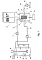
- Figure 1 is a schematic diagram of an apparatus for carrying out the method according to the invention.
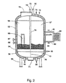
- Figure 2 is schematic cross-sectional view of a preferred type of reservoir for preparing and supplying the treating liquid.
- Fig. 1 schematically shows an apparatus for applying a treating liquid 10 to a porous body 11 by the method of the invention.
- the apparatus comprises a treating chamber 12 having an upper part 14 and a lower part 15.
- the upper part 14 is open-topped and may be provided with a removable cover or lid.
- a sealing member 13 consisting of several sections of elastomeric material is arranged to surround a body 11 to be treated when the body is placed in the treating chamber 12 by inserting it into the open top by means of an automatic handling device (not shown).
- an automatic handling device not shown.
- four sections of elastomeric material can be arranged around the four sides, each section being associated with a series of hydraulic, pneumatic or mechanically actuated cylinders, one such hydraulic cylinder 25 being shown in Figure 1.
- Isolation of the upper and lower parts 14, 15 of chamber 12 can be achieved by means of a flexible skirt associated with the sections of the sealing member 13, or by arranging the sections of the sealing member 13 to fluid-tightly protrude from a groove or the like around the chamber wall.
- a supply conduit 16 for treating liquid leads into the upper part 14 of the treating chamber.
- Conduit 16 leads from a reservoir 32 of treating liquid 10 and has a supply pump 17 by means of which treating liquid 10 can be supplied to the upper part 14 of the treating chamber so as to cover the part of the body 11 to be treated, up to a level determined by a sensor 22.
- a Venturi or vacuum pump 18 is connected to the lower part 15 of chamber 12 for evacuating the space around the underside of the body 11.
- air filling the pores of body 11 is evacuated, which causes an amount of the treating liquid 10 in the upper part 14 of chamber 12 to be intaken into the part of the body 11 to be treated.
- a pressure detector 19 is provided in the lower part 15 of chamber 12. This detector 19 is sensitive to the change in pressure which occurs when all of the pores of the part of body 11 being treated are filled.
- An outlet conduit 20 is connected to the bottom of the upper part 14 of the chamber. This conduit 20 leads back to the reservoir 32 and has a pump 21 for returning treating liquid remaining in the chamber at the end of treatment of a body 11 back to the reservoir 32.
- a hydraulic system comprising a hydraulic cylinder 25 controlled by a hydraulic pump 26, is provided for adjusting the sealing member 13 which is connected to a piston of the hydraulic pump 26.
- the member 13 is pulled out to allow a loose fit around a body 11, permitting insertion and removal of the body 11 into or from the treating chamber 12.
- the sealing member 13 is tightened around the body 11 to provide a sealing fit, by elastic deformation of the elastomeric material making up the sections of sealing member 13 when they are applied against the body 11 under the pressure applied by the hydraulic control.
- sealing member 13 pneumatically, mechanically or electromechanically.
- a position detector 30 is provided in the lower part 15 of the treating chamber for detecting when a body 11 introduced into chamber 12 reaches a predetermined position. This position depends on the size of the body 11 and corresponds to the level of the bottom of the body 11 when the top of the body to be treated is at a level where it will be covered by treating liquid 10 in the upper part 14 of the chamber.
- the detector 30 is arranged to actuate the hydraulic pump 26 and hydraulic cylinder 25 to bring the sealing member 13 to sealably engage with the body 11 when the body 11 has reached the given position.
- the treating chamber 12 comprises a heater 31 for heating the treating liquid 10 in the upper part 14 of chamber 12.
- the heater 31 can be an electric heater or can operate by circulating hot air or another heating fluid. This heater 31 can be adjusted to supply an amount of heat which compensates for heat loss due to contact of liquid 10 with body 11, i.e. depending on the size and temperature of the body 11 and its thermal characteristics, and the operating temperature of the treating liquid 10. If required, the heater 31 can be replaced by means for maintaining a proper thermal balance.
- the reservoir 32 supplies hot treating liquid 10 to the top part 14 of the treating chamber and, after the end of the treatment of a body 11, treating liquid remaining is returned to the reservoir 32 via conduit 20.
- the reservoir 32 is externally insulated and is fitted with a heater 33 for maintaining the treating liquid 10 at a selected temperature controlled by a thermostat 37.
- a stirrer 34 constantly or intermittently driven by a motor 35 stirs the treating liquid 10 contained in reservoir 32.
- at the top of reservoir 32 is a metering device 36 for adding components of the treating liquid 10 to the reservoir 32 in an amount to compensate for consumption of the treating liquid 10 in the treating process.
- the reservoir 32 also includes a pressure sensor 38 for monitoring the level of liquid 10 and a sensor 39 measuring the density or the conductivity of liquid 10, serving to control the metering device 36.
- the treating liquid 10 in reservoir 32 is maintained at a selected temperature, say from 60°C to 120°C and contains a treating agent at a concentration well below saturation.
- a selected temperature say from 60°C to 120°C and contains a treating agent at a concentration well below saturation.
- a preferred apparatus comprises a control panel schematically indicated at 40.
- This control panel includes controls for all routine adjustments such as temperature of the liquid in reservoir 32 and in the top part 14 of chamber 12, the liquid level to be controlled by sensor 22, etc.
- the control panel also includes an overall control arranged to sequentially perform the following operations :
- the sealing member 13 is actuated (by the position detector 30 and hydraulic control 26/25) to sealably engage with the body 11 when the body 11 to be treated has reached the given position.
- the pump 17 is switched on to fill the upper part 14 of the treating chamber 12 with a quantity of hot treating liquid 10 from the reservoir 32, up to a level controlled by sensor 22.
- the lower part 15 of the treating chamber is evacuated by switching on the Venturi or vacuum pump 18, which evacuates air from the pores of body 11 and intakes treating liquid 10 into the surface pores.
- the heater 31 is switched on to heat the treating liquid 10 in the upper part 14 of the chamber 12 in order to compensate for cooling of the liquid 10 by contact with body 11, so that the treating liquid 10 in contact with the body 11 remains at more-or-less constant temperature above the saturation temperature. In this way, the treating liquid in the circulation system is always maintained non-saturated, thereby avoiding unwanted deposits of the treating agent in the circulation system.
- the hydraulic pump 26 is actuated to release the sealing member 13 and allow removal of the treated body 11 from the treating chamber 12 by an automatic handling device (not shown).
- a typical body 11 to be treated is a prebaked carbon anode of an aluminium production cell.
- Such bodies usually have a porosity of about 20 - 24%, of which 10 - 12% is open porosity.
- a prebaked anode may weigh of the order of 1000 kg.
- Attached to its upper side of the anode is a steel rod for connection to a suspension device and which also serves as an electrical connection.
- the treatment of prebaked anodes is advantageous, because the anode can be treated with its rodded side up and only the part which needs to be treated (the upper side shoulders and top) can be treated without preheating of the anode, in a simple treatment with the anode at ambient temperature and the treating liquid at a convenient temperature, say from 60° to 120°C in a treatment lasting only a few minutes.
- the treated anode or other body only takes up a small quantity of heat, so the process is very energy efficient.
- the operating cycle is slightly modified, by removing used treating liquid from the bottom part 15 of the chamber after releasing the sealing members 13.
- the used treating liquid flows down and is collected in the lower part of the treating chamber, in a channel or sump at the bottom of an inclined surface down which the liquid flows.
- the outlet 20 then leads from this channel or sump for return of the used liquid to the reservoir.
- a sloping floor ensures continuous draining of the used liquid, which avoids unwanted deposits of the oxidation retardant. This simplifies maintenance of the apparatus and reduces operating costs.
- Figure 2 shows the main components of a very advantageous design of a storage vessel or reservoir 52 for supplying the treating liquid 10 via a supply conduit 16 and returning used treating liquid to the reservoir 52 via a return conduit 20.
- Reservoir 52 is separated by a horizontal inner divider wall 54 into an upper (or first) compartment 55 and a lower (or second) compartment 56.
- the upper compartment 55 contains saturated treating liquid 10" at a temperature T 1 , this saturated treating liquid 10" being in contact with a mass 60 of undissolved treating agent on the divider wall 54.
- the lower compartment 56 contains a supply of non-saturated treating liquid 10 which is at the same concentration as that in compartment 55 but is at a temperature T 2 which is higher than T 1 .
- the reservoir 52 further comprises arrangements for maintaining the hot treating liquid in the compartments 55 and 56 at the respective temperatures T 1 and T 2 .
- compartment 55 such an arrangement comprises an outlet 61 and a return inlet 62 for circulating the hot liquid via a standard type of heat exchanger 63 which heats the circulating liquid to the desired temperature T 1 (or T 2 ).
- a similar arrangement (not shown) is provided for compartment 56.
- These heater/circulating arrangements also serve to stir the liquid in compartments 55 and 56. Additional stirrers can be included if desired.
- Compartment 55 has an outlet 64 and compartment 56 has an inlet 65 via which hot treating liquid 10" from compartment 55 at temperature T 1 can be transferred into compartment 56 where the liquid is maintained at a temperature T 2 above T 1 .
- Heating the liquid from temperature T 1 to T 2 can be done between the outlet 64 and inlet 65, or in a separate heating/circulating device (like 61,62,63).
- the reservoir 52 also has a window 66 in one face, through which the level of the undissolved treating material 60 can be monitored. As shown for compartment 55, a thermometer 67 and a manometer 68 are provided for monitoring the temperatures T 1 (or T 2 ) and the pressure in the respective compartment 55 (or 56).
- a hinged cover 70 which can be manually opened for tipping into the compartment 55 a fresh supply of material 60 when needed, as can be visually ascertained by inspection via window 66.
- the material 60 can thus be supplied at convenient times by emptying it, for example from a sack.
- the cover 70 is fitted with a seal to prevent the escape of fumes.
- an optional manhole-type opening 71 that can be opened for manually removing debris etc. that may accumulate in the lower compartment 56.
- the lower compartment is fitted with a perforated dividing wall 76 for restraining the debris.
- the reservoir further comprises a hot water inlet 72 and a hot water outlet 73 at the top of compartment 55. It thus possible to include, inside the main compartment 55 of the reservoir 52, an internal hot water storage tank arranged so that, when needed, the stored hot water can be used to flush the conduits 61, 62 and the heat exchanger 63 to dissolve any deposits of the treating material deposited from the saturated liquid.
- each of the upper and lower compartments 55, 56 has a venting device for equalizing pressure therein.
- This consists of a vent tube 74, which connects the compartment 56 to the outside, having a spring-actuated closure flap 74' for venting in case of excess pressure in the compartment 56.
- compartment 55 has a vent tube 75 closed by a spring-actuated closure flap 75'.
- the described improved reservoir 52 can be used for supplying hot treating liquid for various processes; i.e. even without using a vacuum. For instance, it can be used to spray or otherwise apply a topcoating of the treating material onto a treated body.
- This reservoir 52 is very advantageous from several points of view.
- the treating material therein is maintained dissolved, at a concentration which corresponds to the saturation concentration at that temperature T 1 . This is achieved without any complex control means and without a need to meter in selected amounts of the treating material, simply by maintaining an excess of undissolved treating material 60, by adequate stirring, and by maintaining the temperature at the desired value T 1 .
- the solution in this compartment 56 is dissolved at the same concentration as before, but is sufficiently below the saturation concentration that when the liquid is supplied for example to the upper part of chamber 14, the risk of unwanted deposition of the treating material in the supply arrangement is reduced or eliminated, compared to when a liquid at or near saturation is used.
- the concentration of the treating liquid is controlled in a very simple way.
- the reservoir 52 can be filled manually at convenient intervals with fresh treating material 60.
- the simple arrangement with sealed cover 70 avoids the escape of undesirable fumes.
- the used treating liquid instead of returning the used treating liquid into compartment 56 via the conduit 70, it could be returned into compartment 55.
- the supplied treating liquid need not be returned to the reservoir.
- a saturated solution of boric acid can be contained in compartment 55 at a temperature T 1 in the range 50°C to 110°C, for example.
- the sub-saturated treating solution 10 can be obtained by heating the solution in compartment 56 to a temperature say about 10°C to 15°C above T 1 .
- this sub-saturated solution is impregnated into the surface of a carbon anode 11 at ambient temperature assisted by vacuum, and maintaining the external solution hot by means of the heater 31, a boron-containing layer precipitates in the pores underneath the surface of the carbon body 11.
- the impregnated layer vitrifies and forms a dense viscous protective layer considerably reducing oxidation of the upper part of the anode which remains as an anode butt.
Landscapes
- Chemical & Material Sciences (AREA)
- Engineering & Computer Science (AREA)
- Ceramic Engineering (AREA)
- Materials Engineering (AREA)
- Organic Chemistry (AREA)
- Structural Engineering (AREA)
- Metallurgy (AREA)
- Electrochemistry (AREA)
- Chemical Kinetics & Catalysis (AREA)
- Battery Electrode And Active Subsutance (AREA)
- Chemically Coating (AREA)
- Application Of Or Painting With Fluid Materials (AREA)
- Carbon And Carbon Compounds (AREA)
- Ceramic Products (AREA)
- Materials For Medical Uses (AREA)
- Weting (AREA)
- Physical Or Chemical Processes And Apparatus (AREA)
Claims (41)
- Verfahren zur Behandlung eines offenporigen porösen Körpers (11), der oxidierenden Bedingungen oder anderen chemischen Angriffen bei hohen Temperaturen ausgesetzt werden soll, um den Körper gegen Oxidierung oder chemische Angriff bei den hohen Temperaturen zu schützen, wobei das Verfahren umfaßt:wobei die präzipitierte Schicht des Behandlungsmittels innerhalb des Körpers, wenn der Körper den hohen Temperaturen ausgesetzt wird, eine Schutzschicht in den Oberflächenporen bildet, die den Körper gegen Oxidierung oder andere chemische Angriffe schützt.(a) Bringen einer heißen Behandlungsflüssigkeit (10), die ein gelöstes Behandlungsmittel in einer Konzentration unterhalb der Sättigungskonzentration enthält, in Kontakt mit der Oberfläche des Körpers (11) bei einer Temperatur, die ungefähr bei oder gerade über der Umgebungstemperatur liegt, wobei die heiße Behandlungsflüssigkeit eine Temperatur oberhalb der Temperatur des Körpers hat und die Konzentration des Behandlungsmittels in der heißen Behandlungsflüssigkeit so ist, daß, wenn die Flüssigkeit auf die Temperatur des Körpers abgekühlt wird, die Flüssigkeit gesättigt wird und das Behandlungsmittel präzipitiert; und(b) Bewirken eines Druckgefälles, damit die Behandlungsflüssigkeit in die Oberflächenporen des Körpers imprägniert und damit sich innerhalb der Poren des Körpers (11) unterhalb der Oberfläche eine Schicht des Behandlungsmittels ablagert, das aus der Flüssigkeit innerhalb des Körpers durch Kühlen präzipitiert wird, wenn die Flüssigkeit die Poren des Körpers imprägniert;
- Verfahren nach Anspruch 1, bei dem die Behandlungslösung eine lösliche Borverbindung umfaßt, die eine visköse Schutzschicht bei Temperaturen oberhalb von 400 °C bildet.
- Verfahren nach Anspruch 1, bei dem das Bewirken des Druckgefälles die Poren mit Behandlungsflüssigkeit auffüllt, wobei das Bewirken des Druckgefälles mindestens solange fortgesetzt wird, bis alle Poren des behandelten Teils des Körpers gefüllt sind.
- Verfahren nach Anspruch 1, bei dem das Druckgefälle bewirkt wird, indem ein Vakuum an einen Teil des Körpers angelegt wird, der keinen Kontakt mit der Behandlungsflüssigkeit hat.
- Verfahren nach Anspruch 1, bei dem die Behandlungsflüssigkeit eine Temperatur von mindestens 5 °C oberhalb der Temperatur hat, bei der die Behandlungsflüssigkeit mit dem Behandlungsmittel gesättigt ist.
- Verfahren nach Anspruch 5, bei dem die Behandlungsflüssigkeit eine Temperatur von mindestens 10 °C oberhalb der Temperatur hat, bei der die Behandlungsflüssigkeit mit dem Behandlungsmittel gesättigt ist.
- Verfahren nach Anspruch 5, bei dem die aufgebrachte Behandlungsflüssigkeit eine Temperatur von mindestens 20 °C oberhalb der Temperatur des zu behandelnden Körpers hat.
- Verfahren nach Anspruch 5, bei dem die Behandlungsflüssigkeit bei einer Temperatur im Bereich von 60 °C bis 120 °C zugeführt wird.
- Verfahren nach Anspruch 8, bei dem die Behandlungsflüssigkeit, die mit dem Körper Kontakt hat, durch Heizen bei der Temperatur im Bereich von 60 °C bis 120 °C gehalten wird, um den Wärmeverlust aufgrund des Kontakts der Behandlungsflüssigkeit mit dem Körper (11) zu kompensieren.
- Verfahren nach Anspruch 7, bei dem der behandelte Körper eine Temperatur im Bereich von 20 °C bis 50 °C hat.
- Verfahren nach Anspruch 1, mit dem Zuführen von heißer Behandlungsflüssigkeit (10) aus einem Behältnis (32, 52) zu dem zu behandelnden Körper (11); Zurückleiten von nicht-imprägnierter Behandlungsflüssigkeit nach der Behandlung in das Behältnis (32, 52); und Zugeben von Bestandteilen der Behandlungsflüssigkeit in das Behältnis, um den Verbrauch der Behandlungsflüssigkeit in dem Behandlungsprozeß zu kompensieren.
- Verfahren nach Anspruch 1, mit dem Bereitstellen einer gesättigten Lösung (10") des Behandlungsmittels bei einer gegebenen Temperatur (T1) und dem Ableiten einer Behandlungsflüssigkeit, die eine nicht-gesättigte Lösung (10) des Behandlungsmittels umfaßt, aus der gesättigten Lösung.
- Verfahren nach Anspruch 12, bei dem die Behandlungsflüssigkeit, die die nicht-gesättigte Lösung (10) umfaßt, aus der gesättigten Lösung (10") durch Erhöhen von deren Temperatur abgeleitet wird, wobei die nicht-gesättigte Lösung das Behandlungsmittel bei der gleichen Konzentration enthält, die der Sättigungskonzentration bei der gegebenen Temperatur (T1) entspricht, aber eine höhere Temperatur (T2) hat.
- Verfahren nach Anspruch 1, nacheinander umfassend:(a) Aufbringen von heißer Behandlungsflüssigkeit auf die Oberfläche des zu behandelnden Körpers;(b) Anlegen eines Vakuums an einen nicht zu behandelnden Teil des Körpers;(c) Zuführen von Wärme zur Behandlungsflüssigkeit, die in Kontakt mit dem Körper ist, um Wärmeverlust aufgrund des Kontaktes der Flüssigkeit mit dem Körper zu kompensieren;(d) Beendigen des Anlegens eines Vakuums; und(e) Entfernen von nicht-imprägnierter Behandlungsflüssigkeit.
- Verfahren nach Anspruch 11, bei dem die Behandlungsflüssigkeit mindestens eine lösliche Bor- und/oder Phosphorverbindung enthält.
- Verfahren nach Anspruch 15, bei dem die Behandlungsflüssigkeit eine Bor-enthaltende Flüssigkeit ist, die auf B2O3, Borsäure, Tetraborsäure oder Salzen dieser Säuren basiert.
- Verfahren nach Anspruch 15, bei dem die Behandlungsflüssigkeit Monoaluminiumphosphat, Aluminiumphosphat, Aluminiumpolyphosphat, Aluminiummetaphosphat oder eine Mischung daraus enthält.
- Verfahren nach Anspruch 15, 16 oder 17, bei dem die Behandlungsflüssigkeit außerdem eine Siliciumverbindung enthält, wie Siliciumdioxid oder Borsilikat.
- Verfahren nach einem der vorhergehenden Ansprüche, bei dem die Behandlungsflüssigkeit außerdem eine Suspension von partikulärem Material enthält, das beim Verstopfen von den Poren des Körpers und/oder bei der Bildung der Schutzschicht unterstützend wirkt.
- Verfahren nach Anspruch 19, bei dem die Suspension mindestens eines enthält von: ein Kolloid, das aus kolloidalem Aluminiumoxid, Siliciumdioxid, Yttriumoxid, Ceroxid, Thoriumdioxid, Zirkoniumdioxid, Magnesiumoxid, Lithiumoxid, Monoaluminiumphosphat oder Ceracetat ausgewählt ist; eine Suspension von Aluminiumoxid, Siliciumdioxid, Yttriumdioxid, Ceroxid, Thoriumdioxid, Zirkoniumdioxid, Magnesiumoxid, Lithiumoxid, Monoaluminiumphosphat oder Ceracetat; partikuläre feuerbeständige Boride; Aluminiumpulver, -chips oder -schnippsel; Kohlenstoffpulver; und Mischungen davon.
- Verfahren nach einem der vorhergehenden Ansprüche, bei dem die Schicht aus Behandlungsmittel selektiv auf mindestens einen Teil des Körpers aufgebracht wird, und mindestens eine weitere Behandlung an mindestens einem weiteren Teil des Körpers vorgenommen wird.
- Verfahren nach einem der vorhergehenden Ansprüche, bei dem mindestens ein Teil der Schicht aus Behandlungsmittel durch das Aufbringen eines schützenden Materials deckbeschichtet wird.
- Verfahren nach Anspruch 1, bei dem der behandelte Körper eine vorgebrannte Kohlenstoff-Anode (11) einer Aluminiumproduktionszelle ist.
- Verfahren nach Anspruch 23, bei dem die Anode (11) einen Stab aufweist, der an der oberen Fläche davon angebracht ist, um die Anode mit einer Aufhängeeinrichtung zu verbinden und zur Elektrizitätsversorgung, bei dem der obere Teil der Anode behandelt wird, wobei die mit dem Stab versehene obere Fläche der Anode oben ist.
- Verfahren nach Anspruch 1, bei dem der behandelte Körper Teil einer Kohlenstoffseitenwand einer Aluminiumproduktionszelle ist.
- Verfahren nach Anspruch 1, bei dem der behandelte Körper ein Kohlenstoffkathodenblock einer Aluminiumproduktionszelle ist.
- Vorrichtung zum Aufbringen einer Behandlungsflüssigkeit auf einen offenporigen porösen Körper bei einer Temperatur, die ungefähr bei oder gerade über der Umgebungstemperatur liegt, durch das Verfahren nach Anspruch 1, wobei die Vorrichtung aufweist:A) ein Behältnis (32, 52), das eine Zuführung von heißer Behandlungsflüssigkeit (10) aufweist, die ein gelöstes Behandlungsmittel in einer Konzentration unterhalb der Sättigungskonzentration enthält, wobei die heiße Behandlungsflüssigkeit (10) eine Temperatur oberhalb der Temperatur des Körpers (11) hat und die Konzentration des Behandlungsmittels in der heißen Behandlungsflüssigkeit so ist, daß, wenn die Lösung auf die Temperatur des Körpers abgekühlt wird, die Lösung gesättigt und das Behandlungsmittel präzipitiert wird;B) eine Einrichtung (16, 17) für die Zuführung der heißen nicht-gesättigten Behandlungsflüssigkeit aus dem Behältnis, um mit einem zu behandelnden Teil des Körpers (11) in Kontakt zu kommen;C) eine Einrichtung (18), um ein Druckgefälle an einen nicht zu behandelnden Teil des Körpers anzulegen, damit eine Aufnahme einer Menge der Behandlungsflüssigkeit (10) in Poren des zu behandelnden Teils des Körpers (11) erfolgt und daß sich dabei in den Poren des Körpers unterhalb der Oberfläche durch Kühlen eine Schicht des Behandlungsmittels innerhalb des Körpers ablagert, wenn es die Poren des Körpers imprägniert; undD) eine Einrichtung (20, 21), um nicht gebrauchte Behandlungsflüssigkeit zu entfernen.
- Vorrichtung nach Anspruch 27, außerdem mit einer Behandlungskammer (12) und zumindest einem Dichtungsbauteil (13), das angeordnet ist, um an einem zu behandelnden Körper (11) angelegt zu werden, der sich in der Behandlungskammer bei einer Temperatur ungefähr bei oder gerade oberhalb der Umgebungstemperatur befindet, um einen oberen Teil (14) der Behandlungskammer um den zu behandelnden Teil des Körpers herum von einem unteren Teil (15) der Behandlungskammer um einen unteren Teil des Körpers herum zu isolieren, der nicht behandelt werden soll, wobei die Einrichtung (16, 17) zur Zuführung der heißen nicht-gesättigten Behandlungsflüssigkeit angeordnet ist, um die heiße Behandlungsflüssigkeit (10) zum oberen Teil (14) der Behandlungskammer zu führen.
- Vorrichtung nach Anspruch 28, bei der die Behandlungskammer (12) eine Einrichtung (31) zum Erhitzen der Behandlungsflüssigkeit in dem oberen Teil (14) der Behandlungskammer hat, um den Wärmeverlust aufgrund des Kontakts der Flüssigkeit mit dem Körper (11) zu kompensieren.
- Vorrichtung nach Anspruch 27 oder 28, bei der das Behältnis (32) eine Einrichtung (36) zum Zugeben von Bestandteilen der Behandlungsflüssigkeit in das Behältnis (32) aufweist, um den Verbrauch von Behandlungsflüssigkeit während des Behandlungsvorgangs zu kompensieren.
- Vorrichtung nach Anspruch 30, bei der das Behältnis (32) erste und zweite Abschnitte (55, 56) umfaßt, wobei der erste Abschnitt (55) eine Reservezuführung (10") der heißen Behandlungsflüssigkeit enthält, in Kontakt mit einer Menge (60) des Behandlungsmittels bei einer gegebenen Temperatur (T1), bei der das Behandlungsmittel bei einer Konzentration gelöst ist, die der Sättigungskonzentration bei dieser Temperatur entspricht; der zweite Abschnitt (56) eine Zuführung von nicht-gesättigter Behandlungsflüssigkeit (10) enthält, in der das Behandlungsmittel in der gleichen Konzentration gelöst ist, aber bei einer Temperatur (T2) oberhalb der ausgewählten Temperatur (T1) oder bei der gleichen Temperatur, aber in einer geringen Konzentration, wobei das Behältnis (52) außerdem aufweist:(a) eine Einrichtung (61, 62, 63), um die heiße Behandlungsflüssigkeit in jedem der ersten und zweiten Abschnitte (55, 56) bei der entsprechenden Temperatur zu halten;(b) eine Austrittsleitung (16), um die nicht-gesättigte heiße Behandlungsflüssigkeit (10) aus dem zweiten Abschnitt (56) des Behälters zuzuführen, um den Körper zu behandeln; und(c) eine Leitung (64, 65), um heiße Behandlungsflüssigkeit (10") aus dem ersten Abschnitt (55) zu dem zweiten Abschnitt (56) zu leiten, um den Verbrauch/Verlust an Behandlungsflüssigkeit bei der Behandlung des Körpers zu kompensieren.
- Vorrichtung nach einem der Ansprüche 27 bis 32, bei dem die Behandlungsflüssigkeit mindestens eine lösliche Bor- und/oder Phosphorverbindung enthält.
- Vorrichtung nach Anspruch 32, bei der die Behandlungsflüssigkeit eine Bor-enthaltende Flüssigkeit ist, die auf B2O3, Borsäure, Tetraborsäure, Salze dieser Säuren oder Borsilikat basiert.
- Vorrichtung nach Anspruch 32, bei der die Behandlungsflüssigkeit Monoaluminiumphosphat, Aluminiumphosphat, Aluminiumpolyphosphat, Aluminiummetaphosphat oder eine Mischung davon umfaßt.
- Vorrichtung nach einem der Ansprüche 27 bis 34, bei der die Behandlungsflüssigkeit außerdem zumindest eine Siliciumverbindung enthält, wie Siliciumdioxid oder Borsilikat.
- Vorrichtung nach einem der Ansprüche 27 bis 35, bei der die Behandlungsflüssigkeit eine Suspension eines partikulären Materials enthält, das beim Verstopfen der Poren des Körpers unterstützend wirkt.
- Vorrichtung nach Anspruch 36, bei der die Suspension mindestens eines enthält von: ein Kolloid, das aus kolloidalem Aluminiumoxid, Siliciumdioxid, Yttriumdioxid, Ceroxid, Thoriumdioxid, Zirkoniumdioxid, Magnesiumoxid, Lithiumoxid, Monoaluminiumphosphat oder Ceracetat ausgewählt ist; eine Suspension von partikulärem Aluminiumoxid, Siliciumdioxid, Yttriumdioxid, Ceroxid, Thoriumdioxid, Zirkoniumdioxid, Magnesiumoxid, Lithiumoxid, Monoaluminiumphosphat oder Ceracetat; partikuläre feuerfeste Boride; Aluminiumpulver, -chips oder -schnippsel; Kohlenstoffpulver; und Mischungen davon.
- Vorrichtung nach Anspruch 28, bei der der untere Teil (15) der Behandlungskammer (12) eine geneigte Oberfläche hat, die zu einem Auffangbecken oder Kanal zum Sammeln von verbleibender Behandlungsflüssigkeit führt.
- Verwendung der Vorrichtung nach einem der Ansprüche 27 bis 38 zum Aufbringen einer Behandlungsflüssigkeit auf einen vorgebrannten Kohlenstoffbestandteil von einer Aluminiumproduktionszelle.
- Verwendung nach Anspruch 39, bei der der Bestandteil ein Anodenblock ist, der an seiner oberen Fläche einen Stab zum Aufhängen der Anode und zur Stromversorgung aufweist.
- Verwendung nach Anspruch 39, bei der der Bestandteil ein Kathodenblock oder ein Zellenseitenwandblock ist.
Applications Claiming Priority (5)
| Application Number | Priority Date | Filing Date | Title |
|---|---|---|---|
| WOPCT/IB96/00042 | 1996-01-18 | ||
| IB9600042 | 1996-01-18 | ||
| IB9601114 | 1996-10-18 | ||
| WOPCT/IB96/01114 | 1996-10-18 | ||
| PCT/IB1997/000008 WO1997026226A1 (en) | 1996-01-18 | 1997-01-09 | Protection of porous bodies against oxidation |
Publications (2)
| Publication Number | Publication Date |
|---|---|
| EP0874789A1 EP0874789A1 (de) | 1998-11-04 |
| EP0874789B1 true EP0874789B1 (de) | 2000-04-26 |
Family
ID=26318665
Family Applications (2)
| Application Number | Title | Priority Date | Filing Date |
|---|---|---|---|
| EP97900018A Expired - Lifetime EP0874789B1 (de) | 1996-01-18 | 1997-01-09 | Schutz von porösen körpern gegen oxidation |
| EP97900386A Withdrawn EP0932590A1 (de) | 1996-01-18 | 1997-01-10 | Verfahren und vorrichtung zum aufbringen einer gehandlungsflüssigkeit auf einen porösen körper |
Family Applications After (1)
| Application Number | Title | Priority Date | Filing Date |
|---|---|---|---|
| EP97900386A Withdrawn EP0932590A1 (de) | 1996-01-18 | 1997-01-10 | Verfahren und vorrichtung zum aufbringen einer gehandlungsflüssigkeit auf einen porösen körper |
Country Status (6)
| Country | Link |
|---|---|
| US (2) | US6228424B1 (de) |
| EP (2) | EP0874789B1 (de) |
| AU (2) | AU708859B2 (de) |
| CA (2) | CA2243358C (de) |
| DE (1) | DE69701788T2 (de) |
| WO (2) | WO1997026226A1 (de) |
Families Citing this family (21)
| Publication number | Priority date | Publication date | Assignee | Title |
|---|---|---|---|---|
| CA2243358C (en) * | 1996-01-18 | 2007-03-13 | Moltech Invent S.A. | Protection of porous bodies against oxidation |
| IN195165B (de) * | 1996-06-21 | 2005-01-28 | Engelhard Corp | |
| US5985114A (en) * | 1997-09-15 | 1999-11-16 | Moltech Invent S.A. | Carbon bodies resistant to deterioration by oxidizing gases |
| GB9805815D0 (en) | 1998-03-19 | 1998-05-13 | Johnson Matthey Plc | Manufacturing process |
| US6404204B1 (en) * | 2000-05-01 | 2002-06-11 | ARETé ASSOCIATES | Sensor and sensor system for liquid conductivity, temperature and depth |
| US6884467B2 (en) * | 2002-08-20 | 2005-04-26 | Honeywell International Inc. | Method for simultaneously protecting carbon-containing components against catalytic oxidation and high temperature non-catalytic oxidation |
| EP1573889A1 (de) * | 2002-12-10 | 2005-09-14 | Koninklijke Philips Electronics N.V. | Integrierte halbbrückenleistungsschaltung |
| FR2858318B1 (fr) * | 2003-07-31 | 2007-03-02 | Snecma Propulsion Solide | Protection contre l'oxydation de pieces en materiau composite contenant du carbone et pieces ainsi protegees |
| US8051796B2 (en) * | 2003-10-23 | 2011-11-08 | Fanuc Robotics America, Inc. | Robotic apparatus and method for painting |
| GB0405015D0 (en) * | 2004-03-05 | 2004-04-07 | Johnson Matthey Plc | Method of loading a monolith with catalyst and/or washcoat |
| FR2889186B1 (fr) * | 2005-08-01 | 2008-01-04 | Messier Bugatti Sa | Procede anti-oxydation de pieces en un materiau composite contenant du carbone |
| US8239063B2 (en) * | 2008-07-29 | 2012-08-07 | Fanuc Robotics America, Inc. | Servo motor monitoring and hood/deck exchange to enhance the interior coating process |
| CA2731484C (en) * | 2008-08-06 | 2017-03-07 | Basf Se | Positioning device and method with rotary indexing table for monolith-based automobile and chemical catalysts |
| US8911824B2 (en) * | 2008-12-31 | 2014-12-16 | Zircoa, Inc. | Method of impregnating crucibles and refractory articles |
| US10655219B1 (en) * | 2009-04-14 | 2020-05-19 | Goodrich Corporation | Containment structure for creating composite structures |
| DE102011005813A1 (de) | 2011-03-18 | 2012-09-20 | Chemische Fabrik Budenheim Kg | Flüssiges phosphathaltiges Bindemittel |
| CN103909038B (zh) * | 2013-01-07 | 2017-06-13 | 通用电气公司 | 浸渍涂层装置及应用该装置制备电极的方法 |
| CN103741167A (zh) * | 2013-12-25 | 2014-04-23 | 中国矿业大学 | 一种提高电解铝用炭阳极抗氧化性的方法 |
| CN109225753A (zh) * | 2018-11-13 | 2019-01-18 | 江苏龙共真空技术有限公司 | 真空压力浸渍系统的工作方法 |
| CN114016087B (zh) * | 2021-10-28 | 2025-03-25 | 黄治齐 | 一种高效硅硼体系浸渍剂配方及其制备与应用工艺 |
| CN114940628B (zh) * | 2022-06-22 | 2022-12-06 | 湖南晶碳新材料有限公司 | 一种用于浸渍的焙烧品预处理装置 |
Family Cites Families (24)
| Publication number | Priority date | Publication date | Assignee | Title |
|---|---|---|---|---|
| US1818976A (en) * | 1930-09-22 | 1931-08-18 | Westinghouse Electric & Mfg Co | Method of impregnating coils |
| US2290671A (en) * | 1940-03-26 | 1942-07-21 | Gen Electric | Insulated conducting member and method of applying the insulation |
| US3104987A (en) * | 1960-01-19 | 1963-09-24 | V L Smithers Mfg Company | Suction head for saturating foam blocks |
| US3084662A (en) * | 1960-08-10 | 1963-04-09 | Afton C Badger | Apparatus for the continuous application of coating to strip material |
| GB1074386A (en) * | 1964-08-19 | 1967-07-05 | Dowty Technical Dev Ltd | Hydraulic axial piston pumps and motors |
| US3510347A (en) * | 1964-09-02 | 1970-05-05 | Carborundum Co | Oxidation resistant carbon |
| US3900866A (en) * | 1972-07-10 | 1975-08-19 | Leeds & Northrup Co | Apparatus for and method of graphical recording |
| US4038939A (en) * | 1974-10-21 | 1977-08-02 | Universal Oil Products Company | Continuous system for providing a catalytic coating on support members |
| US4191126A (en) * | 1978-01-19 | 1980-03-04 | General Motors Corporation | Apparatus for coating catalyst supports |
| EP0047275B1 (de) * | 1980-03-14 | 1986-09-03 | Ultraseal International Limited | Imprägnieren poröser körper |
| JPS5954683A (ja) * | 1982-09-20 | 1984-03-29 | 日本碍子株式会社 | セラミツクハニカム構造体の開口端面封止方法 |
| US4454193A (en) * | 1983-02-28 | 1984-06-12 | Union Oil Company Of California | Carbon-metal phosphate ester composite and method of making |
| US4550034A (en) * | 1984-04-05 | 1985-10-29 | Engelhard Corporation | Method of impregnating ceramic monolithic structures with predetermined amounts of catalyst |
| US4609563A (en) * | 1985-02-28 | 1986-09-02 | Engelhard Corporation | Metered charge system for catalytic coating of a substrate |
| JP2575824B2 (ja) * | 1988-07-05 | 1997-01-29 | 株式会社神戸製鋼所 | 含浸炭化方法及び装置 |
| JP2948678B2 (ja) * | 1991-04-24 | 1999-09-13 | 玄々化学工業株式会社 | 減圧塗装装置 |
| US5651874A (en) * | 1993-05-28 | 1997-07-29 | Moltech Invent S.A. | Method for production of aluminum utilizing protected carbon-containing components |
| SK127895A3 (en) * | 1993-04-19 | 1996-02-07 | Moltech Invent Sa | Working of electrolyzer components for aluminium production |
| SK142095A3 (en) * | 1993-06-02 | 1997-05-07 | Moltech Invent Sa | Treating prebaked carbon anodes for aluminium production |
| US5534130A (en) * | 1994-06-07 | 1996-07-09 | Moltech Invent S.A. | Application of phosphates of aluminum to carbonaceous components of aluminum production cells |
| CA2138434C (fr) * | 1994-12-19 | 1996-09-03 | Maurice Perron | Semelle isolante et therapeutique |
| US5753382A (en) * | 1996-01-10 | 1998-05-19 | Moltech Invent S.A. | Carbon bodies resistant to deterioration by oxidizing gases |
| CA2243358C (en) * | 1996-01-18 | 2007-03-13 | Moltech Invent S.A. | Protection of porous bodies against oxidation |
| IN195165B (de) * | 1996-06-21 | 2005-01-28 | Engelhard Corp |
-
1997
- 1997-01-09 CA CA002243358A patent/CA2243358C/en not_active Expired - Fee Related
- 1997-01-09 US US09/101,417 patent/US6228424B1/en not_active Expired - Fee Related
- 1997-01-09 EP EP97900018A patent/EP0874789B1/de not_active Expired - Lifetime
- 1997-01-09 AU AU11684/97A patent/AU708859B2/en not_active Ceased
- 1997-01-09 DE DE69701788T patent/DE69701788T2/de not_active Expired - Fee Related
- 1997-01-09 WO PCT/IB1997/000008 patent/WO1997026226A1/en not_active Ceased
- 1997-01-10 US US09/101,427 patent/US6455097B1/en not_active Expired - Fee Related
- 1997-01-10 CA CA002242387A patent/CA2242387C/en not_active Expired - Fee Related
- 1997-01-10 EP EP97900386A patent/EP0932590A1/de not_active Withdrawn
- 1997-01-10 WO PCT/IB1997/000009 patent/WO1997026227A1/en not_active Ceased
- 1997-01-10 AU AU13959/97A patent/AU707517B2/en not_active Ceased
Also Published As
| Publication number | Publication date |
|---|---|
| US6228424B1 (en) | 2001-05-08 |
| AU707517B2 (en) | 1999-07-15 |
| AU1395997A (en) | 1997-08-11 |
| CA2243358C (en) | 2007-03-13 |
| WO1997026227A1 (en) | 1997-07-24 |
| US6455097B1 (en) | 2002-09-24 |
| WO1997026226A1 (en) | 1997-07-24 |
| DE69701788D1 (de) | 2000-05-31 |
| AU708859B2 (en) | 1999-08-12 |
| AU1168497A (en) | 1997-08-11 |
| CA2242387A1 (en) | 1997-07-24 |
| CA2243358A1 (en) | 1997-07-24 |
| DE69701788T2 (de) | 2000-11-23 |
| EP0932590A1 (de) | 1999-08-04 |
| CA2242387C (en) | 2007-04-10 |
| EP0874789A1 (de) | 1998-11-04 |
Similar Documents
| Publication | Publication Date | Title |
|---|---|---|
| EP0874789B1 (de) | Schutz von porösen körpern gegen oxidation | |
| CA2161541C (en) | Treating prebaked carbon anodes for aluminium production | |
| US5486278A (en) | Treating prebaked carbon components for aluminum production, the treated components thereof, and the components use in an electrolytic cell | |
| US20020079231A1 (en) | Start-up of aluminium electrowinning cells | |
| RU2266983C1 (ru) | Катодная футеровка алюминиевого электролизера | |
| EP1366215B1 (de) | Gegen korrosiven hochtemperaturumgebungen beständige wärmeisolierende bauteile | |
| US5578174A (en) | Conditioning of cell components for aluminum production | |
| US3738918A (en) | Reduction of aluminum with improved reduction cell and anodes | |
| US5753382A (en) | Carbon bodies resistant to deterioration by oxidizing gases | |
| US4998710A (en) | Apparatus for holding and refining of molten aluminum | |
| RU2283372C2 (ru) | Электролизер для электрохимического получения алюминия, работающий с анодами на основе металла | |
| AU2002236144A1 (en) | Thermally insulating structural components resistant to high temperature corrosive media | |
| CA2268931A1 (en) | The start-up of aluminium electrowinning cells | |
| EP0701635A1 (de) | Behandlung von vorgebrannten anoden für die herstellung von aluminium | |
| CA2029750C (en) | Apparatus for holding and refining of molten aluminum | |
| US20090114547A1 (en) | Aluminium Electrowinning Cell with Enhanced Crust | |
| AU2002236145B2 (en) | Cell for the electrowinning of aluminium operating with metal-based anodes | |
| HU217324B (hu) | Eljárás alumínium előállítására szolgáló, szénalapú szerkezeti elemek kezelésére, és elektrolizálócella | |
| AU2002236145A1 (en) | Cell for the electrowinning of aluminium operating with metal-based anodes |
Legal Events
| Date | Code | Title | Description |
|---|---|---|---|
| PUAI | Public reference made under article 153(3) epc to a published international application that has entered the european phase |
Free format text: ORIGINAL CODE: 0009012 |
|
| 17P | Request for examination filed |
Effective date: 19980702 |
|
| AK | Designated contracting states |
Kind code of ref document: A1 Designated state(s): DE ES FR GB IT NL |
|
| GRAG | Despatch of communication of intention to grant |
Free format text: ORIGINAL CODE: EPIDOS AGRA |
|
| 17Q | First examination report despatched |
Effective date: 19990312 |
|
| GRAG | Despatch of communication of intention to grant |
Free format text: ORIGINAL CODE: EPIDOS AGRA |
|
| GRAG | Despatch of communication of intention to grant |
Free format text: ORIGINAL CODE: EPIDOS AGRA |
|
| GRAH | Despatch of communication of intention to grant a patent |
Free format text: ORIGINAL CODE: EPIDOS IGRA |
|
| GRAH | Despatch of communication of intention to grant a patent |
Free format text: ORIGINAL CODE: EPIDOS IGRA |
|
| GRAA | (expected) grant |
Free format text: ORIGINAL CODE: 0009210 |
|
| AK | Designated contracting states |
Kind code of ref document: B1 Designated state(s): DE ES FR GB IT NL |
|
| PG25 | Lapsed in a contracting state [announced via postgrant information from national office to epo] |
Ref country code: NL Free format text: LAPSE BECAUSE OF FAILURE TO SUBMIT A TRANSLATION OF THE DESCRIPTION OR TO PAY THE FEE WITHIN THE PRESCRIBED TIME-LIMIT Effective date: 20000426 Ref country code: IT Free format text: LAPSE BECAUSE OF FAILURE TO SUBMIT A TRANSLATION OF THE DESCRIPTION OR TO PAY THE FEE WITHIN THE PRESCRIBED TIME-LIMIT;WARNING: LAPSES OF ITALIAN PATENTS WITH EFFECTIVE DATE BEFORE 2007 MAY HAVE OCCURRED AT ANY TIME BEFORE 2007. THE CORRECT EFFECTIVE DATE MAY BE DIFFERENT FROM THE ONE RECORDED. Effective date: 20000426 Ref country code: ES Free format text: THE PATENT HAS BEEN ANNULLED BY A DECISION OF A NATIONAL AUTHORITY Effective date: 20000426 |
|
| REF | Corresponds to: |
Ref document number: 69701788 Country of ref document: DE Date of ref document: 20000531 |
|
| ET | Fr: translation filed | ||
| NLV1 | Nl: lapsed or annulled due to failure to fulfill the requirements of art. 29p and 29m of the patents act | ||
| PLBE | No opposition filed within time limit |
Free format text: ORIGINAL CODE: 0009261 |
|
| STAA | Information on the status of an ep patent application or granted ep patent |
Free format text: STATUS: NO OPPOSITION FILED WITHIN TIME LIMIT |
|
| 26N | No opposition filed | ||
| REG | Reference to a national code |
Ref country code: GB Ref legal event code: IF02 |
|
| PGFP | Annual fee paid to national office [announced via postgrant information from national office to epo] |
Ref country code: DE Payment date: 20061227 Year of fee payment: 11 |
|
| PGFP | Annual fee paid to national office [announced via postgrant information from national office to epo] |
Ref country code: GB Payment date: 20061228 Year of fee payment: 11 |
|
| PGFP | Annual fee paid to national office [announced via postgrant information from national office to epo] |
Ref country code: FR Payment date: 20070129 Year of fee payment: 11 |
|
| GBPC | Gb: european patent ceased through non-payment of renewal fee |
Effective date: 20080109 |
|
| PG25 | Lapsed in a contracting state [announced via postgrant information from national office to epo] |
Ref country code: DE Free format text: LAPSE BECAUSE OF NON-PAYMENT OF DUE FEES Effective date: 20080801 |
|
| REG | Reference to a national code |
Ref country code: FR Ref legal event code: ST Effective date: 20081029 |
|
| PG25 | Lapsed in a contracting state [announced via postgrant information from national office to epo] |
Ref country code: GB Free format text: LAPSE BECAUSE OF NON-PAYMENT OF DUE FEES Effective date: 20080109 |
|
| PG25 | Lapsed in a contracting state [announced via postgrant information from national office to epo] |
Ref country code: FR Free format text: LAPSE BECAUSE OF NON-PAYMENT OF DUE FEES Effective date: 20080131 |