EP0874657B1 - Eine einen isolierten Operationsraum für das distale Ende der Speiseröhre erzeugende Sonde - Google Patents
Eine einen isolierten Operationsraum für das distale Ende der Speiseröhre erzeugende Sonde Download PDFInfo
- Publication number
- EP0874657B1 EP0874657B1 EP97900737A EP97900737A EP0874657B1 EP 0874657 B1 EP0874657 B1 EP 0874657B1 EP 97900737 A EP97900737 A EP 97900737A EP 97900737 A EP97900737 A EP 97900737A EP 0874657 B1 EP0874657 B1 EP 0874657B1
- Authority
- EP
- European Patent Office
- Prior art keywords
- probe
- bladders
- length
- bladder
- channel
- Prior art date
- Legal status (The legal status is an assumption and is not a legal conclusion. Google has not performed a legal analysis and makes no representation as to the accuracy of the status listed.)
- Expired - Lifetime
Links
- 239000000523 sample Substances 0.000 title claims abstract description 41
- 230000002496 gastric effect Effects 0.000 claims abstract description 9
- 206010046996 Varicose vein Diseases 0.000 claims abstract description 8
- 208000027185 varicose disease Diseases 0.000 claims abstract description 8
- 230000000740 bleeding effect Effects 0.000 claims abstract description 7
- 238000000034 method Methods 0.000 claims description 12
- 244000043261 Hevea brasiliensis Species 0.000 claims description 4
- 229920003052 natural elastomer Polymers 0.000 claims description 4
- 229920001194 natural rubber Polymers 0.000 claims description 4
- 239000002131 composite material Substances 0.000 claims description 2
- 230000023597 hemostasis Effects 0.000 claims description 2
- 239000012815 thermoplastic material Substances 0.000 claims description 2
- 230000004323 axial length Effects 0.000 claims 1
- 239000007787 solid Substances 0.000 claims 1
- 239000008280 blood Substances 0.000 abstract description 16
- 210000004369 blood Anatomy 0.000 abstract description 16
- 238000001839 endoscopy Methods 0.000 abstract description 10
- 208000034189 Sclerosis Diseases 0.000 abstract description 8
- 238000004140 cleaning Methods 0.000 abstract description 7
- 238000010992 reflux Methods 0.000 abstract description 6
- 210000002784 stomach Anatomy 0.000 abstract description 4
- 206010035664 Pneumonia Diseases 0.000 abstract description 3
- 230000002265 prevention Effects 0.000 abstract description 3
- 230000000903 blocking effect Effects 0.000 abstract description 2
- 230000002349 favourable effect Effects 0.000 abstract description 2
- 210000002345 respiratory system Anatomy 0.000 abstract description 2
- 210000001187 pylorus Anatomy 0.000 description 3
- 238000005406 washing Methods 0.000 description 3
- XLYOFNOQVPJJNP-UHFFFAOYSA-N water Substances O XLYOFNOQVPJJNP-UHFFFAOYSA-N 0.000 description 3
- 238000001574 biopsy Methods 0.000 description 2
- 230000015271 coagulation Effects 0.000 description 2
- 238000005345 coagulation Methods 0.000 description 2
- 230000002183 duodenal effect Effects 0.000 description 2
- 230000010412 perfusion Effects 0.000 description 2
- 239000000932 sedative agent Substances 0.000 description 2
- 230000001624 sedative effect Effects 0.000 description 2
- 206010010071 Coma Diseases 0.000 description 1
- 206010011224 Cough Diseases 0.000 description 1
- 206010015137 Eructation Diseases 0.000 description 1
- 206010016654 Fibrosis Diseases 0.000 description 1
- 208000010378 Pulmonary Embolism Diseases 0.000 description 1
- 206010038776 Retching Diseases 0.000 description 1
- 208000007536 Thrombosis Diseases 0.000 description 1
- 208000024780 Urticaria Diseases 0.000 description 1
- 210000003484 anatomy Anatomy 0.000 description 1
- 210000002318 cardia Anatomy 0.000 description 1
- 230000006835 compression Effects 0.000 description 1
- 238000007906 compression Methods 0.000 description 1
- 230000001419 dependent effect Effects 0.000 description 1
- 230000008034 disappearance Effects 0.000 description 1
- 230000008030 elimination Effects 0.000 description 1
- 238000003379 elimination reaction Methods 0.000 description 1
- 230000004761 fibrosis Effects 0.000 description 1
- 238000002347 injection Methods 0.000 description 1
- 239000007924 injection Substances 0.000 description 1
- 239000007788 liquid Substances 0.000 description 1
- 239000000463 material Substances 0.000 description 1
- 210000004877 mucosa Anatomy 0.000 description 1
- 238000005192 partition Methods 0.000 description 1
- 239000003229 sclerosing agent Substances 0.000 description 1
- 238000001356 surgical procedure Methods 0.000 description 1
- 230000001225 therapeutic effect Effects 0.000 description 1
Images


Classifications
-
- A—HUMAN NECESSITIES
- A61—MEDICAL OR VETERINARY SCIENCE; HYGIENE
- A61M—DEVICES FOR INTRODUCING MEDIA INTO, OR ONTO, THE BODY; DEVICES FOR TRANSDUCING BODY MEDIA OR FOR TAKING MEDIA FROM THE BODY; DEVICES FOR PRODUCING OR ENDING SLEEP OR STUPOR
- A61M25/00—Catheters; Hollow probes
- A61M25/10—Balloon catheters
- A61M25/1011—Multiple balloon catheters
-
- A—HUMAN NECESSITIES
- A61—MEDICAL OR VETERINARY SCIENCE; HYGIENE
- A61M—DEVICES FOR INTRODUCING MEDIA INTO, OR ONTO, THE BODY; DEVICES FOR TRANSDUCING BODY MEDIA OR FOR TAKING MEDIA FROM THE BODY; DEVICES FOR PRODUCING OR ENDING SLEEP OR STUPOR
- A61M2210/00—Anatomical parts of the body
- A61M2210/10—Trunk
- A61M2210/1042—Alimentary tract
- A61M2210/105—Oesophagus
Definitions
- the present invention relates to the surgery field and, more particularly, a probe which facilitates the execution, as an endoscopy, of a haemostasis (sclerosis or binding of varices) in case of bleeding.
- Sclerosing or binding the bleeding varices of the oesophagus is an operating endoscopy which is executed on a hypovolaemic, often hyperammoniaemic patient markedly intolerant of movements which are not directed to a determined end or controllable either.
- An endoscopy should first locate the bleeding source and then carry out the operation as quickly as possible because of the precarious patient's conditions.
- the surgeon meets with a number of problems. First of all, administering a sedative to such patients is dangerous.
- US-A-5314409 discloses an esophageal perfusion catheter having an outer housing, a plurality of flexible, tubular channel members within said housing, and two spaced balloon members encompassing said catheter.
- Said esophageal perfusion catheter was not designed neither for the emergency treatement of the bleeding varices of the oesophagus, nor for any other endoscopic therapeutic treatment. Further, the aspiration holes can easily be obstructed by the blood clots, in this way impeding the draining and the cleaning of the operating room defined by the inflated balloons in the oesophagus.
- DE-A-3640034 which is used as a basis for the preamble of claim 1, envisages the introduction of an endoscope into a fenestrated tube sheath which is equipped with two balloons that form a chamber.
- the endoscope carries out the sclerosis on the variceal piles which result to be procidentiae in the lumen of the tube itself and it allows suction of the haematic content from the stomach through said fenestration. It is easy to observe that given the technical conditions in which the work should be carried out, it would indeed be rather cumbersome to carry out a ligature using the device described in said document, which was conceived when ligature was carried out using techniques which had not been sufficiently tested and refined.
- a probe having the characteristics recited in claim 1, which may be operated by a different operator from that one operating the endoscopy and allows the operating area to be isolated from the gastric cavity and the proximal end of the oesophagus by inflating two pneumatic bladders.
- proximal indicates the segment or the tract of the outer side of the device located closer to the mouth.
- distal will be used thereafter with the meaning that such a term has in anatomy, i.e. that tract, element or end located away from a conventional point of origin, that is the mouth in case of the alimentary canal.
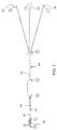
- the probe of the invention looks exteriorly like a tubular member of flexible material having a circular cross section and connecting, at its distal end, two pneumatic inflatable bladders at a suitable axial distance from each other, said bladders having different forms and larger diameters than the tubular member which moreover divides, at its proximal end, into two further tubular members of lower diameters.
- the main tubular member is inside divided by partition walls into three channels, two of which having circular cross sections and communicating with a respective bladder which may be then inflated through the relative channel.
- the third channel is the central main tubular member embracing the two minor channels and passing through the bladders without communicating therewith.
- the tubular member is provided with a plurality of through holes providing a direct communication between the operating area and the outside so as to prevent any increase in the pressure as a result of air insufflation into the two bladders.
- the length of the tubular member after the proximal bladder is completely closed and carries a slidable coil provided with a small ring for hanging possible weights.
- Such a length ends at the proximal end outside the mouth of the patient where, as mentioned above, the tubular member divides into three tubular members.
- the two inner channels, through which air can be insufflated into the bladders separate from the main tubular member outside the patient's mouth so as to form independent tubular members having circular cross section and lumen lower than the main tubular member.
- the device or probe of the invention consists of a composite, flexible tubular member which in a preferred embodiment has the length of 180 cm and is formed of a pipe A-H of circular section which divides at F into further two tubular members FG and FI having circular sections and reduced diameters.
- Two pneumatic chambers or bladders BC and DE are located in the main tubular member between A and F.
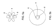
- Bladder BC is of natural rubber and, by way of example, has a width of 1.5 cm, a length of 3 cm under deflated conditions and a six-radius-symmetry form or other forms. It should be noted that such dimensions as well as those indicated thereafter are not binding as they may be varied as a function of the operating conditions and the particular patient.
- bladder DE is of natural rubber and, by way of example, has a width of 2.5 cm, a length of 8 cm under deflated conditions and a circular section.
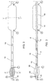
- the length of the tubular member between the two bladders BC and DE is perforated.
- the holes 10 of ellipsoidal form are preferably in a number of eight.
- the first two holes (major axis 7 mm, minor axis 3 mm) from bladder BC are diametrically opposed but offset to each other by the same length as the major axis.
- the other holes of the same dimensions are also diametrically opposed with parallel major axes and offset to one another by a length as high as the double of their major axis.
- a first length of 5 cm from bladder BC of the tubular member between bladders BC and DE has a colour which is different from that of the remaining pipe.
- the length between point A and bladder BC is provided with a crossing hole 18 of 2 mm diameter, ends in a round form and has a length of 1 cm (Fig. 2).
- the inner structure of the probe is now described with reference to the longitudinal section of Fig. 3.
- the length of pipe between point A and point B has no lumen.
- the length of pipe from point B to point F has a wall thickness of 0.5 mm and an inner diameter of the larger main channel, indicated at 4 and including two further channels 6 and 8, of 3 mm.
- Channels 6 and 8 have a lumen of 1 mm and are located in parallel on either inner side of the main channel 4 at the same distance from the centre thereof.
- channels 6 and 8 have a length which is different from that of channel 4.
- Channel 8 has the function of insufflating air into bladder DE through four holes 19 of 2 mm diameter.
- the other channel 6 has the function of insufflating air into bladder BC through two holes 20 of 2 mm diameter.
- the two channels 6 and 8 are closed at their initial ostium by plugs integral therewith 22, 24, respectively (Fig. 1).
- the length F-H of the tubular member has at its proximal end (point H) a flared terminal 23.
- the probe is made of thermoplastic material except for the bladders which are of natural rubber.
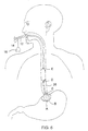
- the gastric cavity is isolated from the oesophagus tract by inflating the distal bladder BC. Thereafter the operator introduces the endoscopy into the operating area by slipping it along the side of the proximal, still deflated bladder DE.
- the proximal tract of the oesophagus is isolated from the operating area 26 where the endoscopy carries out the sclerosis (Fig. 6).
- Operating area 26 communicates with the outside through the holes 10 of the main tubular member 4, which prevents any increase in the pressure caused by air insufflation into the probe.
- the same holes 10 are also used for continuously cleaning the operating area: any liquid inlet may either be sucked through such holes 10 or through the channel of the endoscopy (not shown in the figures).
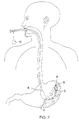
- the probe is removed by deflating the two bladders and its slotted part is brought to the best possible position for the suction of blood by means of a polypus loop or biopsy pliers, as shown in Fig. 7.
- a polypus loop or biopsy pliers as shown in Fig. 7.
- some absolutely not removable coagulation generally remains so that the third step, i.e. the Duodenal Time, is required.
- the distal bladder is positioned (Fig. 8) in the bulb by means of biopsy pliers or a loop engaging the towing cable of the probe and then it is attached to pylorus by a suitable insufflation. This is the only way to remove at best blood and coagulation because of the strategic position of the distal bladder in the bulb and the provision of the holes allowing washing and suction during the 24 hours.
Landscapes
- Health & Medical Sciences (AREA)
- Life Sciences & Earth Sciences (AREA)
- Heart & Thoracic Surgery (AREA)
- Animal Behavior & Ethology (AREA)
- Public Health (AREA)
- Pulmonology (AREA)
- Engineering & Computer Science (AREA)
- Anesthesiology (AREA)
- Biomedical Technology (AREA)
- Hematology (AREA)
- Child & Adolescent Psychology (AREA)
- General Health & Medical Sciences (AREA)
- Biophysics (AREA)
- Veterinary Medicine (AREA)
- Endoscopes (AREA)
- Surgical Instruments (AREA)
- Ultra Sonic Daignosis Equipment (AREA)
- Valve Device For Special Equipments (AREA)
- Finger-Pressure Massage (AREA)
- Mechanical Operated Clutches (AREA)
- Medical Preparation Storing Or Oral Administration Devices (AREA)
Claims (14)
- Sonde zur leichteren Durchführung von Hämostasetechniken bei Varizenblutungen im Ösophagus, bestehend aus einer zusammengesetzten, flexiblen Vorrichtung röhrenförmiger Gestalt, die in Querrichtung in drei Kanäle (4, 6, 8) unterteilt und an ihrem distalen Ende mit zwei Blasen (BC, DE) versehen ist, die im axialen Abstand voneinander angeordnet und mittels Luft, die durch zwei Kanäle (6, 8) eingeblasen wird, unabhängig voneinander aufblasbar sind, so dass es beim Aufblasen der beiden Blasen (BC, DE) möglich ist, die axiale Länge zwischen den beiden Blasen von der Magenhöhle und dem proximalen Trakt das Ösophagus zu isolieren und so einen isolierten Operationsraum (26) am distalen Ende des Ösophagus zu bilden, wobei der Operationsraum (26) über den Kanal (4), der nicht mit den Blasen (BC, DE) verbunden ist, stets mit der Außenseite in Verbindung bleibt, wobei einer der drei Kanäle (4, 6, 8) einen größeren Durchmesser aufweist und die anderen beiden Kanäle mit den entsprechend kleineren Durchmessern enthält, wobei der Kanal (4) mit dem größeren Durchmesser mit durchgehenden Löchern (10) in der Länge zwischen den Blasen (BC, DE) zum Herstellen einer direkten Verbindung zwischen der Sonde und der Außenseite versehen ist, wobei jeder Kanal (6, 8) mit kleinerem Durchmesser mit einer der beiden Blasen (BC, DE) verbunden ist, dadurch gekennzeichnet, dass die proximale Blase (DE) eine Länge von 8 cm und einen kreisförmigen Abschnitt mit einem Durchmesser von 2,5 cm unter Deflationsbedingungen aufweist, während die distale Blase (BC) eine Länge von 3 cm und einen Durchmesser von 1,5 cm unter Deflationsbedingungen aufweist, die zwischen den beiden Blasen (BC, DE) angeordneten Löcher (10) im Kanal mit dem größeren Durchmesser (4) in einer Anzahl von acht Löchern vorliegen, eine ellipsoide Form mit der Hauptachse parallel zur Achse des Kanals aufweisen und in vier Paaren sich diametral gegenüberliegend auf dem Umfang des größeren Kanals im Abstand von den Kanälen mit kleinerem Durchmesser angeordnet sind, die Kanäle mit dem kleineren Durchmesser mit den jeweiligen Blasen (BC, DE) über Löcher (19, 20) in Verbindung stehen, die in einer Anzahl von vier Löchern in der proximalen Blase (DE) und in einer Anzahl von zwei Löchern in der distalen Blase (BC) angeordnet sind, wobei diese Löcher (19, 20) kreisförmig sind, einen Durchmesser von 2 mm aufweisen und im Abstand von 14 mm voneinander in Reihe entlang nur eines Teils des Umfangs des jeweiligen Kanals (6, 8) angeordnet sind.
- Sonde nach Anspruch 1, worin die Sonde eine Länge von ca. 180 cm, eine Wanddicke von 0,5 mm, einen Innendurchmesser des größeren Kanals (4) von 3 mm und einen Innendurchmesser der kleineren Kanäle (6, 8) von 1 mm aufweist.
- Sonde nach Anspruch 1, worin die röhrenförmige Konstruktion aus einem beliebigen thermoplastischen Material besteht, mit Ausnahme der Blasen (BC, DE), die aus Naturkautschuk bestehen.
- Sonde nach Anspruch 1, worin die ersten, der distalen Blase (BC) näher liegenden, beiden Löcher (10) sich diametral gegenüberstehen und über die Länge ihrer Hauptachse gegeneinander versetzt sind, während die restlichen Löcher (10) über eine Länge, die doppelt so lang sein kann wie ihre Hauptachse, gegeneinander versetzt sind.
- Sonde nach Anspruch 1 und 4, worin die Länge der Hauptachse der Löcher (10) 7 mm und die Länge der Nebenachse 3 mm betragen.
- Sonde nach Anspruch 1, worin die Kanäle (6, 8) mit kleinerem Durchmesser innerhalb der Blasen (BC, DE) verlaufende Gänge bilden, wodurch die kreisförmigen Löcher (19, 20) in den jeweiligen Gängen angeordnet sind.
- Sonde nach Anspruch 1, worin eine (BC) der beiden Blasen am distalen Ende der Sonde angeordnet ist und kleinere Abmessungen aufweist als die andere Blase (DE), die proximal relativ zur ersten Blase angeordnet ist und eine längliche Gestalt und einen kreisförmigen Querschnitt aufweist.
- Sonde nach Anspruch 1 und 7, worin die Abstände des proximalen Endes und des distalen Endes der längeren Blase (DE) vom Ende der Sonde 23,9 cm bzw. 16 cm betragen, während die Abstände des proximalen Endes und des distalen Endes der kürzeren. Blase (BC) vom Ende der Sonde 4 cm bzw. 1 cm betragen, und der Abstand zwischen den beiden Blasen (BC, DE) 12 cm ist.
- Sonde nach Anspruch 1, worin die beiden kleineren Kanäle (6, 8) vom größeren Kanal (4) am proximalen Ende der Sonde über eine Länge von 25 cm getrennt sind und jeweils mit einem einstückig damit geformten Pfropf (22, 24) versehen sind.
- Sonde nach Anspruch 1, worin der größere Kanal (4) an seinem proximalen Ende (H) aufgeweitet ist (23).
- Sonde nach Anspruch 1, worin der, der distalen Blase (BC) näher liegende Abschnitt der Sonde mit den durchgehenden Löchern (10) über einige zentimeter eine andere Farbe aufweist.
- Sonde nach Anspruch 1, worin der Abschnitt des größeren Kanals (4) von der distalen Blase (BC) bis zum Endpunkt (A) der Sonde fest ist, eine Länge von 1 cm aufweist und mit einem durchgehenden Loch (18) mit einem Durchmesser von einigen wenigen Millimetern versehen ist.
- Sonde nach Anspruch 1, worin die Sonde mit einer Spule (12), die über eine Länge (FE) der Sonde gewickelt ist, und mit einem Ring (14) versehen ist, an dem ein Gewicht (16) zum Aufhängen eines festen Subkardia-Zugs befestigt werden kann,
- Sonde nach Anspruch 1, worin die proximale Blase (DE) es dem Chirurg unter Deflationsbedingungen gestattet, ein Endoskop zum Operationsraum zu schieben.
Applications Claiming Priority (3)
| Application Number | Priority Date | Filing Date | Title |
|---|---|---|---|
| IT1996CE000001A IT1302994B1 (it) | 1996-01-19 | 1996-01-19 | Camera operatoria blindata esofago distale |
| ITCE960001 | 1996-01-19 | ||
| PCT/IT1997/000010 WO1997026040A1 (en) | 1996-01-19 | 1997-01-17 | An isolated operating-room providing probe for the distal end of the oesophagus |
Publications (2)
| Publication Number | Publication Date |
|---|---|
| EP0874657A1 EP0874657A1 (de) | 1998-11-04 |
| EP0874657B1 true EP0874657B1 (de) | 2002-11-13 |
Family
ID=11347306
Family Applications (1)
| Application Number | Title | Priority Date | Filing Date |
|---|---|---|---|
| EP97900737A Expired - Lifetime EP0874657B1 (de) | 1996-01-19 | 1997-01-17 | Eine einen isolierten Operationsraum für das distale Ende der Speiseröhre erzeugende Sonde |
Country Status (7)
| Country | Link |
|---|---|
| EP (1) | EP0874657B1 (de) |
| AT (1) | ATE227596T1 (de) |
| AU (1) | AU1319097A (de) |
| DE (1) | DE69717070T2 (de) |
| ES (1) | ES2185899T3 (de) |
| IT (1) | IT1302994B1 (de) |
| WO (1) | WO1997026040A1 (de) |
Families Citing this family (5)
| Publication number | Priority date | Publication date | Assignee | Title |
|---|---|---|---|---|
| IT1305291B1 (it) * | 1999-01-26 | 2001-05-04 | Mario Immacolato Paternuosto | Perfezionamento ad una sonda atta a realizzare una camera operatoriaisolata esofago distale. |
| US20050245788A1 (en) * | 2004-04-28 | 2005-11-03 | Medtronic, Inc. | Esophageal delivery system and method with position indexing |
| FR2897540A1 (fr) * | 2006-02-20 | 2007-08-24 | Philippe Zerbib | Sonde gastrique permettant d'eviter le reflux gastro-oesophagien |
| US7654264B2 (en) * | 2006-07-18 | 2010-02-02 | Nellcor Puritan Bennett Llc | Medical tube including an inflatable cuff having a notched collar |
| US7828767B2 (en) | 2008-05-29 | 2010-11-09 | Boston Scientific Scimed, Inc. | Balloon design and weld design to increase ease of re-wrapping and decrease withdrawal force |
Family Cites Families (5)
| Publication number | Priority date | Publication date | Assignee | Title |
|---|---|---|---|---|
| US4022216A (en) * | 1975-08-11 | 1977-05-10 | Stevens Robert C | Urological catheter |
| SE455368B (sv) * | 1986-11-11 | 1988-07-11 | Roger Hellgren | Anordning for nedleggning i tunntarmen i och for intestinal aspiration/perfusion |
| DE3640034A1 (de) * | 1986-11-24 | 1988-05-26 | Georg E Prof Dr Med Vogel | Speiseroehrensonde |
| DE3915289A1 (de) * | 1989-05-10 | 1990-11-15 | Josef Dieter Dr Med Nagel | Vierlumige doppel-ballonsonde |
| US5314409A (en) * | 1993-03-11 | 1994-05-24 | Uva Patents Foundation | Catheter for esophageal perfusion |
-
1996
- 1996-01-19 IT IT1996CE000001A patent/IT1302994B1/it active IP Right Grant
-
1997
- 1997-01-17 WO PCT/IT1997/000010 patent/WO1997026040A1/en not_active Ceased
- 1997-01-17 DE DE69717070T patent/DE69717070T2/de not_active Expired - Fee Related
- 1997-01-17 ES ES97900737T patent/ES2185899T3/es not_active Expired - Lifetime
- 1997-01-17 AU AU13190/97A patent/AU1319097A/en not_active Abandoned
- 1997-01-17 AT AT97900737T patent/ATE227596T1/de not_active IP Right Cessation
- 1997-01-17 EP EP97900737A patent/EP0874657B1/de not_active Expired - Lifetime
Also Published As
| Publication number | Publication date |
|---|---|
| IT1302994B1 (it) | 2000-10-18 |
| ITCE960001A1 (it) | 1997-07-19 |
| ES2185899T3 (es) | 2003-05-01 |
| ATE227596T1 (de) | 2002-11-15 |
| EP0874657A1 (de) | 1998-11-04 |
| AU1319097A (en) | 1997-08-11 |
| DE69717070T2 (de) | 2003-07-17 |
| ITCE960001A0 (it) | 1996-01-19 |
| WO1997026040A1 (en) | 1997-07-24 |
| DE69717070D1 (de) | 2002-12-19 |
Similar Documents
| Publication | Publication Date | Title |
|---|---|---|
| US5785684A (en) | Apparatus and method for the deployment of an esophagastric balloon tamponade device | |
| US4447227A (en) | Multi-purpose medical devices | |
| US5613950A (en) | Multifunctional manipulating instrument for various surgical procedures | |
| KR100470519B1 (ko) | 백-업 보유 부재 배출 카테테르 | |
| US4842583A (en) | Colonic irrigation tube | |
| JP6933733B2 (ja) | 子宮タンポナーデ組立体用のイントロデューサ、及びその使用方法 | |
| US5709657A (en) | Methods for placement of balloon tamponade devices | |
| US20110172491A1 (en) | Detachable balloon catheter | |
| US11583281B2 (en) | Introducer for uterine tamponade assembly with echogenic element and methods of using the same | |
| US20120123463A1 (en) | Mechanically-guided transoral bougie | |
| CN114641265A (zh) | 在手术期间使用拉普拉斯定律张力回缩进行手术的系统和方法 | |
| CN111629643B (zh) | 内窥镜外套管和内窥镜 | |
| JP2002508195A (ja) | 制御される密閉バルブを有する腹腔鏡手術用アクセスポート | |
| CN102665577A (zh) | 外科手术装置和附件 | |
| JP2003520098A (ja) | ガス・シールを備えた腹腔鏡手術用接近工具 | |
| CN108888854A (zh) | 一种间距可调式双球囊灌注导管及其使用方法 | |
| MXPA06001498A (es) | Sistema de lavado gastrointestinal. | |
| US9486240B2 (en) | Inflatable instrument for transanal minimal invasive surgery | |
| EP3823513A1 (de) | Verfahren und vorrichtung zur manipulation der seitenwand eines körperlumens oder körperhohlraums zur verbesserten visualisierung davon und/oder für verbesserten zugang dazu und/oder zur stabilisierung von instrumenten im zusammenhang damit | |
| EP0874657B1 (de) | Eine einen isolierten Operationsraum für das distale Ende der Speiseröhre erzeugende Sonde | |
| WO2018156774A1 (en) | Method and apparatus for manipulating the side wall of a body lumen or body cavity so as to provide increased visualization of the same and/or increased access to the same, and/or for stabilizing instruments relative to the same | |
| WO2018156768A1 (en) | Method and apparatus for providing increased visualization and manipulation of a body side wall | |
| CN118902531B (zh) | 高精度止血球囊及系统 | |
| AU2023393104A1 (en) | Body fluid regulating apparatus | |
| HK40068226A (en) | Systems and methods of performing surgery using laplace's law tension retraction during surgery |
Legal Events
| Date | Code | Title | Description |
|---|---|---|---|
| PUAI | Public reference made under article 153(3) epc to a published international application that has entered the european phase |
Free format text: ORIGINAL CODE: 0009012 |
|
| 17P | Request for examination filed |
Effective date: 19980807 |
|
| AK | Designated contracting states |
Kind code of ref document: A1 Designated state(s): AT BE CH DE DK ES FI FR GB GR IE IT LI LU MC NL PT SE |
|
| RAP1 | Party data changed (applicant data changed or rights of an application transferred) |
Owner name: PATERNUOSTO, MARIO IMMACOLATO |
|
| 17Q | First examination report despatched |
Effective date: 19991227 |
|
| GRAG | Despatch of communication of intention to grant |
Free format text: ORIGINAL CODE: EPIDOS AGRA |
|
| RTI1 | Title (correction) |
Free format text: AN ISOLATED OPERATING-ROOM PROVIDING PROBE FOR THE DISTAL END OF THE OESOPHAGUS |
|
| GRAG | Despatch of communication of intention to grant |
Free format text: ORIGINAL CODE: EPIDOS AGRA |
|
| GRAH | Despatch of communication of intention to grant a patent |
Free format text: ORIGINAL CODE: EPIDOS IGRA |
|
| GRAH | Despatch of communication of intention to grant a patent |
Free format text: ORIGINAL CODE: EPIDOS IGRA |
|
| GRAA | (expected) grant |
Free format text: ORIGINAL CODE: 0009210 |
|
| AK | Designated contracting states |
Kind code of ref document: B1 Designated state(s): AT BE CH DE DK ES FI FR GB GR IE IT LI LU MC NL PT SE |
|
| PG25 | Lapsed in a contracting state [announced via postgrant information from national office to epo] |
Ref country code: NL Free format text: LAPSE BECAUSE OF FAILURE TO SUBMIT A TRANSLATION OF THE DESCRIPTION OR TO PAY THE FEE WITHIN THE PRESCRIBED TIME-LIMIT Effective date: 20021113 Ref country code: LI Free format text: LAPSE BECAUSE OF FAILURE TO SUBMIT A TRANSLATION OF THE DESCRIPTION OR TO PAY THE FEE WITHIN THE PRESCRIBED TIME-LIMIT Effective date: 20021113 Ref country code: GR Free format text: LAPSE BECAUSE OF FAILURE TO SUBMIT A TRANSLATION OF THE DESCRIPTION OR TO PAY THE FEE WITHIN THE PRESCRIBED TIME-LIMIT Effective date: 20021113 Ref country code: FI Free format text: LAPSE BECAUSE OF FAILURE TO SUBMIT A TRANSLATION OF THE DESCRIPTION OR TO PAY THE FEE WITHIN THE PRESCRIBED TIME-LIMIT Effective date: 20021113 Ref country code: CH Free format text: LAPSE BECAUSE OF FAILURE TO SUBMIT A TRANSLATION OF THE DESCRIPTION OR TO PAY THE FEE WITHIN THE PRESCRIBED TIME-LIMIT Effective date: 20021113 Ref country code: BE Free format text: LAPSE BECAUSE OF FAILURE TO SUBMIT A TRANSLATION OF THE DESCRIPTION OR TO PAY THE FEE WITHIN THE PRESCRIBED TIME-LIMIT Effective date: 20021113 Ref country code: AT Free format text: LAPSE BECAUSE OF FAILURE TO SUBMIT A TRANSLATION OF THE DESCRIPTION OR TO PAY THE FEE WITHIN THE PRESCRIBED TIME-LIMIT Effective date: 20021113 |
|
| REF | Corresponds to: |
Ref document number: 227596 Country of ref document: AT Date of ref document: 20021115 Kind code of ref document: T |
|
| REG | Reference to a national code |
Ref country code: GB Ref legal event code: FG4D |
|
| REG | Reference to a national code |
Ref country code: CH Ref legal event code: EP |
|
| REG | Reference to a national code |
Ref country code: IE Ref legal event code: FG4D |
|
| REF | Corresponds to: |
Ref document number: 69717070 Country of ref document: DE Date of ref document: 20021219 |
|
| PG25 | Lapsed in a contracting state [announced via postgrant information from national office to epo] |
Ref country code: LU Free format text: LAPSE BECAUSE OF NON-PAYMENT OF DUE FEES Effective date: 20030117 Ref country code: IE Free format text: LAPSE BECAUSE OF NON-PAYMENT OF DUE FEES Effective date: 20030117 |
|
| PG25 | Lapsed in a contracting state [announced via postgrant information from national office to epo] |
Ref country code: MC Free format text: LAPSE BECAUSE OF NON-PAYMENT OF DUE FEES Effective date: 20030131 |
|
| PG25 | Lapsed in a contracting state [announced via postgrant information from national office to epo] |
Ref country code: SE Free format text: LAPSE BECAUSE OF FAILURE TO SUBMIT A TRANSLATION OF THE DESCRIPTION OR TO PAY THE FEE WITHIN THE PRESCRIBED TIME-LIMIT Effective date: 20030213 Ref country code: PT Free format text: LAPSE BECAUSE OF FAILURE TO SUBMIT A TRANSLATION OF THE DESCRIPTION OR TO PAY THE FEE WITHIN THE PRESCRIBED TIME-LIMIT Effective date: 20030213 Ref country code: GB Free format text: LAPSE BECAUSE OF NON-PAYMENT OF DUE FEES Effective date: 20030213 Ref country code: DK Free format text: LAPSE BECAUSE OF FAILURE TO SUBMIT A TRANSLATION OF THE DESCRIPTION OR TO PAY THE FEE WITHIN THE PRESCRIBED TIME-LIMIT Effective date: 20030213 |
|
| NLV1 | Nl: lapsed or annulled due to failure to fulfill the requirements of art. 29p and 29m of the patents act | ||
| REG | Reference to a national code |
Ref country code: ES Ref legal event code: FG2A Ref document number: 2185899 Country of ref document: ES Kind code of ref document: T3 |
|
| REG | Reference to a national code |
Ref country code: CH Ref legal event code: PL |
|
| ET | Fr: translation filed | ||
| PLBE | No opposition filed within time limit |
Free format text: ORIGINAL CODE: 0009261 |
|
| STAA | Information on the status of an ep patent application or granted ep patent |
Free format text: STATUS: NO OPPOSITION FILED WITHIN TIME LIMIT |
|
| GBPC | Gb: european patent ceased through non-payment of renewal fee | ||
| 26N | No opposition filed |
Effective date: 20030814 |
|
| REG | Reference to a national code |
Ref country code: IE Ref legal event code: MM4A |
|
| PGFP | Annual fee paid to national office [announced via postgrant information from national office to epo] |
Ref country code: FR Payment date: 20041229 Year of fee payment: 9 |
|
| PGFP | Annual fee paid to national office [announced via postgrant information from national office to epo] |
Ref country code: ES Payment date: 20050118 Year of fee payment: 9 |
|
| PGFP | Annual fee paid to national office [announced via postgrant information from national office to epo] |
Ref country code: DE Payment date: 20050128 Year of fee payment: 9 |
|
| PG25 | Lapsed in a contracting state [announced via postgrant information from national office to epo] |
Ref country code: ES Free format text: LAPSE BECAUSE OF NON-PAYMENT OF DUE FEES Effective date: 20060118 |
|
| PG25 | Lapsed in a contracting state [announced via postgrant information from national office to epo] |
Ref country code: FR Free format text: LAPSE BECAUSE OF NON-PAYMENT OF DUE FEES Effective date: 20060131 |
|
| PGFP | Annual fee paid to national office [announced via postgrant information from national office to epo] |
Ref country code: IT Payment date: 20060131 Year of fee payment: 10 |
|
| PG25 | Lapsed in a contracting state [announced via postgrant information from national office to epo] |
Ref country code: DE Free format text: LAPSE BECAUSE OF NON-PAYMENT OF DUE FEES Effective date: 20060801 |
|
| REG | Reference to a national code |
Ref country code: FR Ref legal event code: ST Effective date: 20060929 |
|
| REG | Reference to a national code |
Ref country code: ES Ref legal event code: FD2A Effective date: 20060118 |
|
| PG25 | Lapsed in a contracting state [announced via postgrant information from national office to epo] |
Ref country code: IT Free format text: LAPSE BECAUSE OF NON-PAYMENT OF DUE FEES Effective date: 20070117 |